Table of Contents
- 1. Packet Filter
- 2. System Configuration
- 3. Caching Name Server
- 4. DNS and DHCP Services
- 5. Time Synchronization with NTP
- 6. Monitoring of Kernun UTM Operation
- 7. Networking in Proxies
- 8. H.323 Proxies
- 9. SIP Proxy
- 10. SQLNet Proxy
- 11. UDP Proxy
- 12. Cooperation of HTTP and FTP Proxies
- 13. Secure Communication Using SSL/TLS
- 14. User Authentication
- 14.1. Authentication Methods
- 14.2. Authentication in FTP Proxy
- 14.3. Basic Authentication in HTTP Proxy
- 14.4. Kerberos Authentication in HTTP Proxy
- 14.5. Kerberos Authentication in Transparent HTTP Proxy
- 14.6. NTLM Authentication in HTTP Proxy
- 14.7. HTTP Authentication Proxy
- 14.8. Out of Band Authentication
- 15. Antivirus Checking of Data
- 16. Antispam Processing of E-mail
- 17. Content Processing
- 18. Filtering HTTP Requests by URI
- 19. HTTPS Inspection
- 20. Adaptive Firewall
- 21. Traffic Shaping
- 22. Virtual Private Networks — OpenVPN
- 23. Virtual Private Networks — IPsec
- 24. High Availability Clusters
- 25. Kernun Branch Access
- 26. IPv6
- 27. Honeypot
This chapter covers the configuration of various advanced features of Kernun UTM. You can find here instructions on how to configure each feature, along with the description of the most important configuration parameters; the remaining ones are listed in the relevant parts of the reference documentation. It is assumed that you know the principles of the Kernun UTM configuration and how to use the Kernun GUI. If not, consult Chapter 4, Configuration Basics and Section 1, “Graphical User Interface”.
In addition to the application layer control, Kernun UTM includes a TCP/IP packet filter with advanced features, such as stateful filtering, network address translation (NAT), traffic normalization, traffic shaping, OS fingerprinting etc. This section offers a general overview of the packet filter's capabilities, as well as examples of a few typical packet filter configurations[24].
It is very important to consider the way packets are handled in Kernun UTM. When combining packet filter rules, traffic shaping and application proxy access control lists, we need to take into account the order, in which network traffic is processed by individual components of the system.
Upon entering the system, network packets get inspected by the packet filter at first. The packet filter itself consists of a number of components. The order, in which these components handle network traffic, is always the same:
State engine
Traffic normalization engine
Traffic shaping / queuing engine
Network address translation engine
Packet filtering engine
This order applies to both incoming and outgoing traffic, i.e. it is the same whether the packet is entering or leaving the system. As regards incoming packets, application proxies may take control only after they are processed by all the packet filter engines. On the other hand, traffic originated at application proxies goes through packet filter engines and then leaves the system for the network.
Important
Network address translation rules always create states. If an initial packet of a connection is translated by an NAT rule and then passed by the packet filter, it is automatically also passed on its way back, thanks to the created state.
As for packet filtering, states are created only if the rules explicitly
specify so using the keep-state modifier. However, if the
raw packet filter rule is specified, the state is kept by default;
if you do not want to keep the state in such a case, you need to add
no state to the raw rule.
The packet filtering rules are defined in the
system.packet-filter section. The following list
introduces its items and subsections:
set-option— a repeatable item containing packet filter specific options, see pf.conf(5);timeouts— a non-repeatable section defining various filter timeouts;altq— the specification of traffic shaping rules, which assign the traffic to individual queues defined in thesystem.pf-queuesections;scrub-acl— the traffic normalization rules; by default, all incoming traffic is normalized and IP fragments are reassembled;rdr-acl— redirection NAT rules, applied to incoming traffic, change the destination address;nat-acl— mapping NAT rules, applied to outgoing traffic, modify the source address;binat-acl— bidirectional NAT rules combine both redirection and mapping;filter-acl— packet filtering, either unidirectional or bidirectional rules (both stateless and stateful);load-anchor— loading of rule subsets from files.
In the following sections we go through several typical
configuration examples that involve capabilities of Kernun UTM's packet filter.
We will start with the initial configuration as described in Section 2, “The Initial Configuration”. The resulting packet filter configurations
can be found in the configuration sample file packet-filter.cml in the
/usr/local/kernun/conf/samples/cml directory.
Packet filtering basically means controlling (either passing, or blocking) network traffic based on basic TCP/IP attributes, including the source and destination IP addresses and ports, the network interface the packet emerges on, its direction (inbound or outbound), and a few other protocol-specific characteristics.
Important
Even if the traffic is passed by the packet filter, there must exist an application proxy with an ACL permitting the communication; otherwise, it is denied. In other words, Kernun UTM does not forward network packets, but instead, it attempts to transparently grab them and process them with application proxies. However, the mechanism of traffic grabbing by application proxies can be bypassed, as described in Section 1.4, “Selective Packet Forwarding”.
Note
By default, the packet filter rules allow all traffic, but there is only a limited set of application proxies in the initial configuration, see Section 2, “The Initial Configuration”.
Blocking traffic using the packet filter may be useful in many situations. For example, we may relieve application proxies of the burden of processing traffic that we know for certain is undesired. Also, application proxies always grab connections, and only then they may selectively deny them. This means that the connection is always established at first, and then immediately closed if denied by a policy. It may be advantageous to pretend to some clients that there is no application proxy in the way, which can be achieved by resetting those connections using the packet filter. Furthermore, there are antispoofing rules to block traffic with faked source addresses, see Section 1.3, “Antispoofing Using Packet Filter”, and it is possible to bypass the application proxy processing and forward some traffic directly to its destination, see Section 1.4, “Selective Packet Forwarding”.
Individual packet-filtering rules are located in filter-acl
subsections within the system.packet-filter configuration section.
The most important items in filter-acl are summarized
here:
from— A set of hosts, addresses and networks that the packet's source address must match. Optionally it may also include constraints concerning source TCP/UDP ports. If omitted, all source addresses and ports match.to— The set of hosts, addresses and networks that the packet's destination address must match. Optionally it may also include constraints concerning destination TCP/UDP ports. If omitted, all destination addresses and ports match.iface— The network interface that this rule applies to. Moreover, the direction of communication may be specified, eitherinfor inbound traffic oroutfor outbound traffic. If this item is not present, the rule applies to all network interfaces and all directions.protocol— The IP protocol that this rule applies to. Protocols are accepted with their symbolic names, such asicmp,udp,tcp, oresp. Moreover, a shortcuttcp-udphas been added for user comfort, meaning both the TCP and UDP protocols. Similarly, the shortcutesp-ahis interpreted as both the ESP and AH protocols[25]. Additional protocol-specific parameters are available for the ICMP and TCP protocols, specificallyicmp-typeto match the ICMP message type, andflagsto match the TCP flags field.deny / accept— Thedenyitem blocks traffic; theacceptitem is used to pass it.keep-state— This item lets the packet filter create a state for the connection as a packet is passed. The following packets in the same connection will then be handled in exactly the same way as the first one, without the need to search the ruleset. Another advantage is that packets of the same connection in the opposite direction are implicitly passed.
Important
Port specification is available only for the TCP and UDP protocols.
Thus, if a port constraint is present in a from or
to item, the protocol item must be specified
and must be one of tcp, udp, or
tcp-udp.
Example: If we want to block the traffic coming in on our external
interface to the TCP port 22, we shall use the to,
iface and deny items, as shown in
Figure 5.1, “A simple blocking packet filter rule”.
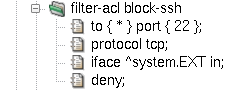
The deny part of the rule means that Kernun UTM will
silently discard packets coming in to port 22. However, this behavior is not very
effective, for several reasons. First, everyone knows that there is
a filter blocking those connections, and that can attract unwanted attention.
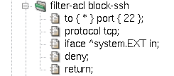
Furthermore, the standard application will not give up if there is no response to
its connection attempts. Therefore, it is customary to send back
information that the port is closed. We will do so by adding a
return item to our filter rule, see Figure 5.2, “A blocking packet filter rule with return”.
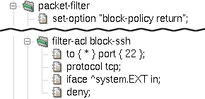
Tip
We can change the packet filter's default behavior of silently
discarding packets by setting the block-policy return option.
If we do so, it will properly react to blocked ports as if those ports were
closed even if there are no return items in individual rules. See
an example in Figure 5.3, “Option block-policy instead of return in rule”.
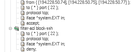
Should some specific clients be allowed to connect to port 22, we have to add a packet filter rule before the blocking rule we have just created. Rule evaluation abides by the so-called first-match principle. This means that rules are evaluated in the order, in which they appear in the configuration, and as soon as a matching rule is found, the evaluation stops and the remaining rules are ignored. Therefore, more specific rules must precede those with more generic matching criteria. Figure 5.4, “More specific rule must come first” shows how to add a rule allowing connections to port 22 to a set of IP addresses, preserving the default behavior of blocking port 22 to other clients.
IP address spoofing is an attack based on counterfeiting the source IP address in order to confuse another computer system. It may be extremely dangerous if attackers from the outside pretend to have an internal source IP addresses; although they never get a response back, it may be sufficient to perform a successful denial-of-service or another kind of attack.
The goal of antispoofing is obviously to prevent spoofing attacks. We can stop intruders from the outside who pretend to have an internal source IP address quite easily. In general, internal network addresses can appear as the source of communication only on the internal network interface. As there may exist more than one protected network interface, this rule can be applied to other networks and interfaces as well.
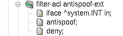
A simple antispoofing rule consists of interface specification
followed by the antispoof and deny items, see
Figure 5.5, “Simple antispoofing rule”. In effect, the internal network
192.168.10.0/24 is blocked when
it appears as a source IP address on any other interface than INT
[26].
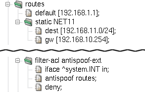
This simple antispoofing rule works for networks directly connected
to named interfaces. However, if our internal network is not flat, but
consists of several routed networks instead, we need to involve all the
internal networks in antispoofing. This can be achieved using the routes
modifier in the antispoof item. The resulting rule is depicted
in Figure 5.6, “Antispoofing rule including routes”.
Note
The routes modifier has an effect
only if there are some routes within the internal network.
To illustrate this fact, the sample configuration file
packet-filter.cml introduces a second internal network,
192.168.11.0/24, specified in
the routes section. Now, both our internal networks,
192.168.10.0/24 and 192.168.11.0/24, get blocked in the source
address field on all interfaces except the internal interface
INT.
Standard routers and filtering gateways accept all network datagrams, and if they are destined for another host, they send them out in accordance with the system's routing table. This mechanism is known under the name forwarding.
Kernun UTM does not forward network packets by default. Only traffic either destined for the system itself or grabbed transparently by application proxies will find its way through; everything else is thrown away. See transparency(7) for more detailed information.
It is possible to bypass application proxies and control the
communication only with packet filter rules. To do so, we need to inform
the transparent grabbing system which packets should be left untouched.
For that purpose, a special tag NOTRANSP has been introduced.
Note
Tagging is a feature of the packet filtering engine; network packets can be assigned a string value that will accompany those packets on their way through the network stack. Other Kernun UTM components may then check which tags, if any, are assigned to traffic they are processing.
Important
The tag name NOTRANSP that the
transparency engine uses to recognize bypassing packets is configurable.
By changing kernel sysctl variable net.inet.ip.no_transp_tag,
we can define another tag string to be used to distinguish between standard
transparent proxy traffic and bypassing datagrams. Sysctl variables (also
called MIBS) are configured in system.sysctl
configuration section, see Section 2.6, “Kernel Parameters in /etc/sysctl.conf”.
To assign a tag to packets, add a tag item to
a filter-acl rule inside the packet-filter section.
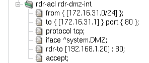
Figure 5.7, “Selective packet forwarding rule” illustrates a rule causing the packet flow
between two hosts to bypass transparent proxy processing, forwarding them
directly to the network in accordance with the system routing table. Note that we have
introduced a new interface, DMZ, representing a demilitarized zone with
public accessible servers. The rule bypass-int-dmz
permits bidirectional traffic between an internal host and a host in the DMZ.
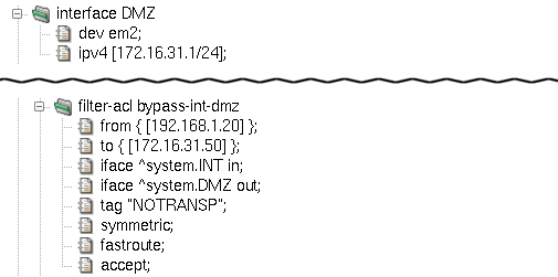
Apart from tag, two more important filter-acl
items are introduced in the sample rule bypass-int-dmz
depicted in Figure 5.7, “Selective packet forwarding rule”:
:
fastroute— This option means that packets get forwarded through Kernun UTM to their destination. It is called selective packet forwarding, as opposed to global forwarding, which is performed by the standard routers and packet filtering gateways. Withoutfastroute, packets taggedNOTRANSPwould not reach their destinations.symmetric— Adds a second rule, allowing traffic in the opposite direction on the same interface. Source and destination IP addresses are swapped in the second rule, as well as the traffic directioninorout. Considering the fact that we have two interface specifications in the rule, we end up with four individual packet flow permissions:Incoming packets on interface
INTgoing from192.168.1.20to172.16.31.50(the basic rule foriface ^system.INT in).Outgoing traffic on interface
INTreturning back from172.16.31.50to192.168.1.20(the symmetric rule foriface ^system.INT in).Outgoing packets on interface
DMZoriginated at192.168.1.20and destined for172.16.31.50(the basic rule foriface ^system.DMZ out).Incoming datagrams on interface
DMZtraveling from172.16.31.50to192.168.1.20(the symmetric rule foriface ^system.DMZ out).
Important
If a packet filter rule sets the NOTRANSP tag for
a packet, a state is automatically created for the packet. This accepts
all following packets of the same connection in both directions. If we
want to selectively forward some communication via the
NOTRANSP mechanism without creating a state, we need to add
an explicit rule that matches the packets and does not contain
keep-state.
There are three types of NAT rules: mapping rules (nat-acl),
redirection rules (rdr-acl) and bidirectional NAT rules
(binat-acl).
Mapping changes source IP addresses (and often ports) of outgoing packets. It always applies to outbound traffic, but it also creates states for backward incoming communication. The state engine fully recognizes individual TCP connections, UDP sessions and ICMP control messages that belong to them. Hence, if a state is created, only legal communication is passed and translated forth and back.
The nat-acl sections allow for a similar set of
items as filter-acl rules. The item from
is used to match source IP addresses and ports, similarly to
is matched against destination IP addresses and ports. The interface
specification may not include the in/out direction as
mapping rules apply only to outbound traffic. The deny
modifier does not block traffic, but effectively denies any NAT mapping if
matched.
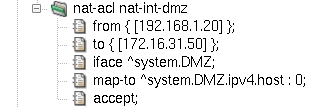
A new important item is introduced for mapping rules:
map-to. Its purpose is to specify the final address
and port combination after the translation.
A sample mapping rule is depicted in Figure 5.8, “Mapping NAT rule”.
It illustrates the use of the map-to item; it
specifies an IP address (using a reference to the outgoing interface's address
^system.DMZ.ipv4.host) and a port (0 in our example,
meaning any port number available).
As always, mapping rules are implemented using the first-match
principle, i.e. the first matching rule is applied immediately, without
consulting the rest of the nat-acl rules.
Unlike mapping, redirection deals with destination IP addresses and ports. Redirection rules are thus applied to the inbound traffic, creating states. The same powerful state engine is in charge of matching backward outgoing packets and changing their addresses and ports back to their original values.
Apart from the target redirection address and port combination,
which is specified using the rdr-to modifier, all other item
names and features are the same in mapping and redirection rules. The
example in Figure 5.9, “Redirection NAT rule” assumes connections from the
172.16.31.0/24 network,
destined for the DMZ interface's local address 172.16.31.1 and port 80. Those
connections get redirected to internal server at 192.168.1.20, port 80.
Imagine that we have an NAT network and want to bypass Kernun for some traffic
(e.g. ICMP packets, in order to be able to ping to the internet from the local
network). For that special case we need to create an NAT rule for the NAT and, at the same time,
tag the traffic with the NOTRANSP tag to forward it, rather than give
it to Kernun's proxies. The NAT rule automatically creates a state, so the reply to the
ping should be delivered to the requester without the need to add any other rule.
However, there is a catch in the PF implementation. The NOTRANSP tag in
combination with NAT rule gets lost and the returning packet is passed to Kernun, rather
than forwarded. For this case, Kernun automatically generates a rule pass any
to any tagged NOTRANSP no state tag NOTRANSP in the pf.conf file, in order
to keep the tag. This rule permanently stores the NOTRANSP tag to the
state of the tagged packet and is not applied to any other packets.
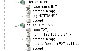
Figure 5.10, “Forwarding of ICMP Packets over NAT” shows a configuration of selective forwarding
of ICMP packets on Kernun UTM for clients behind NAT. The filter-acl ICMP
section tags the packet by the NOTRANSP tag to be passed through Kernun without giving
it to the proxies, while the nat-acl ICMP-NAT rewrites the addresses
and creates a state for the reply packets to be passed back. The returned packets are
first NATed, then the above-mentioned rule is applied and restores the NOTRANSP tag, and
the packet is therefore forwarded into the local network.
The packet filter, together with the network stack in the operating system kernel, provide some means for defense against Denial of Service (DoS) and Distributed Denial of Service (DDoS) attacks. Such attacks try to overload a target computer system or network by sending huge amount of traffic. A DoS attack is originated from a single malicious computer. A DDoS attack is similar, but data are sent by many computers at the same time. It allows the attacker to magnify the number of network packets many times in comparison with a single-origin DoS, hence making the effect on the target network worse and any defense harder.
Basic protection against some (D)DoS attacks on the transport layer of the TCP/IP is built into the network stack of the operating system kernel in form of the SYN cache and SYN cookies. They are effective especially against the SYN flood attack, when the attacker sends many TCP connection requests in the form of TCP SYN segments. The SYN cache keeps information about TCP connection handshakes that have not been completed yet. A SYN cache entry occupies less memory than the full state record of an established TCP connection. Hence the system is able to withstand much more SYNs. SYN cookies take one step further, keeping no state and encoding all information necessary to complete the handshake into the SYN/ACK segment sent to the client.
The SYN cache is always enabled. By default, SYN cookies are also
enabled. They can be disabled by setting the sysctl variable
net.inet.tcp.syncookies=0, see Section 2.6, “Kernel Parameters in /etc/sysctl.conf” for instructions on setting sysctl
variables. SYN cookies are used when the SYN cache becomes full. It is
possible to disable the SYN cache and use only SYN cookies by setting the
sysctl variable net.inet.tcp.syncookies_only=1.
The SYN cache and SYN cookies protect only against SYN flood attacks on TCP-based application protocols handled by a proxy or by a server running locally on the Kernun system. Additional defenses are provided by the packet filter. They are effective for communication handled by the packet filter and not passing via any proxy, but can be combined with a proxy, too. They can also block attacks that perform full TCP handshake and then send excessively large volumes of application-layer data in order to overload a server.
The packet filter allows limiting numbers of simultaneous connections that match a filtering rule or originate from a single source addres. The limits are configured by adding per-rule options. There are two variants how to create such packet filter rules:
A
filter-aclis created with itemkeep-state. A raw option is added by itemoptioncontaining limit specifications delimited by comma, for example,option "keep state (source-track rule, max-src-nodes 100)". Note that “keep state” is specified here, in addition to the separatekeep-stateitem.A
filter-aclis created containing the whole packet filter rule written in arawitem, for example:pass quick inet proto tcp from any to any keep state (max 100)
Available limit specifications are:
maxnumberIt limits the maximum number of simultaneous states (connections) the rule may create. When this limit is reached, further connection attempts are silently dropped. New connections are allowed only after some of the existing states time out. Note that a state times out some time after the related connection is closed.
source-track ruleEnables counting the states created for each individual source IP address. The per-IP limits (e.g.,
max-src-nodesandmax-src-states) are compared to the number of states created by this rule.source-track globalEnables counting the states created for each individual source IP address. The per-IP limits are compared to the sum of states created by all rules that use this option.
max-src-nodesnumberIt limits the maximum number of distinct IP addresses that can have states at the same time.
max-src-statesnumberIt limits the maximum number of states that can be created for a single source IP address.
max-src-statesnumberIt limits the maximum number of established TCP connections that can be created for a single source IP address. In contrast to
max-src-states, this option counts only connection that completed the 3-way TCP handshake.max-src-conn-ratenumber/secondsIt limits the rate of establishing new TCP connections over a time interval.
overload <,table>overload <,table> flushoverload <table> flush globalIf a source IP address reaches one of the limits
max-src-connormax-src-conn-rate, it will be added to a named packet filtertableflushis used, all states created by the matching rule and originating from this IP address will be deleted, effectively terminating all existing connection from the offending IP address. Ifflush globalis used, all states from this IP address are deleted, regardless the rule that created them.
Example: The following rules will block any IP adress that initiates more than 100 HTTP connections per second.
table <dos_attack> persist
block quick from <dos_attack>
pass in proto tcp from any to any port 80 keep state \
    (source-track rule, max-src-conn-rate 100/1, overload <dos_attack> \
    flush global)