Table of Contents
- How to Read the Documentation
- 1. Kernun UTM Product Overview
- 2. Kernun UTM System Management
- 3. User Interface
- 4. Configuration Basics
- 5. Advanced features
- 1. Packet Filter
- 2. System Configuration
- 3. Caching Name Server
- 4. DNS and DHCP Services
- 5. Time Synchronization with NTP
- 6. Monitoring of Kernun UTM Operation
- 7. Networking in Proxies
- 8. H.323 Proxies
- 9. SIP Proxy
- 10. SQLNet Proxy
- 11. UDP Proxy
- 12. Cooperation of HTTP and FTP Proxies
- 13. Secure Communication Using SSL/TLS
- 14. User Authentication
- 14.1. Authentication Methods
- 14.2. Authentication in FTP Proxy
- 14.3. Basic Authentication in HTTP Proxy
- 14.4. Kerberos Authentication in HTTP Proxy
- 14.5. Kerberos Authentication in Transparent HTTP Proxy
- 14.6. NTLM Authentication in HTTP Proxy
- 14.7. HTTP Authentication Proxy
- 14.8. Out of Band Authentication
- 15. Antivirus Checking of Data
- 16. Antispam Processing of E-mail
- 17. Content Processing
- 18. Filtering HTTP Requests by URI
- 19. HTTPS Inspection
- 20. Adaptive Firewall
- 21. Traffic Shaping
- 22. Virtual Private Networks — OpenVPN
- 23. Virtual Private Networks — IPsec
- 24. High Availability Clusters
- 25. Kernun Branch Access
- 26. IPv6
- 27. Honeypot
- I. Kernun UTM Reference (1)
- HtmlMatchPasswd.pm — encapsulates the databases of the HTML form value control tool html-match-db(1) for storing two couples of credentials (internal username and password and external username and password). It also keeps the logs of the actions over the particular accounts.
- clear-web-db-update.sh — tool for updating the Clear Web DataBase
- clear-web-db — tool for managing the Clear Web DataBase
- cluster-sync — tool for synchronizing files between cluster members
- diskdb — tool for creating and querying file system content database
- fwpasswd — create and update password authentication files
- grep-debug — tool for selecting messages from Kernun logs
- grep-stats — tool for selecting messages from Kernun logs
- html-match-db — controls databases of HTML form values used by the generic data matching module
- kernun-audit — checks for bugs and new versions of the Kernun software
- license — tool for checking Kernun license file
- log-ts — tool for selecting messages from Kernun logs
- mkblacklist — tool for converting http-proxy blacklists into DB format
- monitor — report current status of Kernun proxies
- ooba-acs — uses Cisco ACS log to update out of band authentication user list
- ooba-samba — uses a Samba server to update the out of band authentication user list
- oobctl — tool for creating and querying file oob database
- printblacklist — tool for converting http-proxy blacklists into textual format
- quarc.sh — mail quarantine control tool
- resolveblacklist — tool for resolving hostnames in http-proxy blacklists
- rrd — system parameter watching
- sum-stats — generates proxy usage statistics from Kernun logs
- switchlog — distribute messages from Kernun log according to message id and proxy name
- triplicator — SMTP Grey-listing Triplet Database Manipulator
- II. Kernun UTM Reference (5)
- acl — format of acl component configuration
- adaptive-firewall — format of adaptive-firewall component configuration
- alertd — format of alertd component configuration
- alertd.cfg — format of alertd program configuration file
- altq — format of altq component configuration
- antivirus — format of antivirus component configuration
- application — format of application component configuration
- atr — format of atr component configuration
- atrmon.cfg — format of atrmon program configuration file
- auth — format of auth component configuration
- clear-web-db — format of clear-web-db component configuration
- common — format of common component configuration
- cwcatd.cfg — format of cwcatd program configuration file
- dhcp-server — format of dhcp-server component configuration
- dns-proxy — format of dns-proxy component configuration
- dns-proxy.cfg — format of dns-proxy program configuration file
- ftp-proxy — format of ftp-proxy component configuration
- ftp-proxy.cfg — format of ftp-proxy program configuration file
- gk-proxy — format of gk-proxy component configuration
- gk-proxy.cfg — format of gk-proxy program configuration file
- h323-proxy — format of h323-proxy component configuration
- h323-proxy.cfg — format of h323-proxy program configuration file
- http-cache — format of http-cache component configuration
- http-control — format of http-control component configuration
- http-proxy — format of http-proxy component configuration
- http-proxy.cfg — format of http-proxy program configuration file
- ica — format of ica component configuration
- icap-server — format of icap-server component configuration
- icap-server.cfg — format of icap-server program configuration file
- imap4-proxy — format of imap4-proxy component configuration
- imap4-proxy.cfg — format of imap4-proxy program configuration file
- interface — format of interface component configuration
- ipc — format of ipc component configuration
- ipsec — format of ipsec component configuration
- kernun.cml — format of Kernun configuration file
- ldap — format of ldap component configuration
- license — format of license component configuration
- listen-on — format of listen-on component configuration
- log — format of log component configuration
- mod-antispam — format of mod-antispam component configuration
- mod-html-filter — format of mod-html-filter component configuration
- mod-mail-doc — format of mod-mail-doc component configuration
- mod-match — format of mod-match component configuration
- monitoring — format of monitoring component configuration
- nameserver — format of nameserver component configuration
- netio — format of netio component configuration
- nls — format of nls component configuration
- ntp — format of ntp component configuration
- openvpn — format of openvpn component configuration
- packet-filter — format of packet-filter component configuration
- pf-control.cfg — format of pf-control program configuration file
- pf-queue — format of pf-queue component configuration
- pike — format of pike component configuration
- pikemon.cfg — format of pikemon program configuration file
- ping — format of ping component configuration
- pop3-proxy — format of pop3-proxy component configuration
- pop3-proxy.cfg — format of pop3-proxy program configuration file
- proxy-ng — format of proxy-ng component configuration
- radius — format of radius component configuration
- resolver — format of resolver component configuration
- router — format of router component configuration
- rtadvd — format of rtadvd component configuration
- sip-proxy — format of sip-proxy component configuration
- sip-proxy.cfg — format of sip-proxy program configuration file
- smtp-proxy — format of smtp-proxy component configuration
- smtp-proxy.cfg — format of smtp-proxy program configuration file
- snmpd — format of snmpd component configuration
- source-address — format of source-address component configuration
- sqlnet-proxy — format of sqlnet-proxy component configuration
- sqlnet-proxy.cfg — format of sqlnet-proxy program configuration file
- ssh — format of ssh component configuration
- ssl — format of ssl component configuration
- sysctl — format of sysctl component configuration
- system — format of system component configuration
- tcp-proxy — format of tcp-proxy component configuration
- tcp-proxy.cfg — format of tcp-proxy program configuration file
- tcpserver — format of tcpserver component configuration
- test-expr — format of test-expr command-line arguments
- time — format of time component configuration
- udp-proxy — format of udp-proxy component configuration
- udp-proxy.cfg — format of udp-proxy program configuration file
- udpserver — format of udpserver component configuration
- III. Kernun UTM Reference (6)
- ADFI-120 — Application of honeypot blacklist failed
- ADFI-121 — Failure of pfctl operation report
- ADFI-131 — Reading packet filter ips-blacklist table failed
- ADFI-710 — Adaptive Kernun IPS module database refresh report
- ADFI-720 — Adaptive Firewall IPS database refresh report
- ADFI-724 — Client was excluded from the IPS database due to whitelist
- ADFI-729 — Adaptive Firewall IDS database refresh report
- ADFI-730 — Planned refresh of packet filter ips-blacklist table
- ADFI-731 — Current packet filter ips-blacklist table size report
- AFHP-250 — Honeypot module cannost accept new connection
- AFHP-251 — Honeypot module accepted unsupported client
- AFHP-750 — New client was trapped to honeypot
- AFHP-888 — Honeypot module statistics message
- AFLD-709 — Final application termination message
- AFWD-120 — Unrecognized event on watched file
- AFWD-150 — Watched file is not regularly accessible
- AFWD-160 — Watched file is not regularly accessible
- AFWD-670 — Client occurence in watchdog file checked against thresholds
- ALRT-109 — General select() error
- ALRT-159 — Call of snmptrap program has failed
- ALRT-259 — SNMP trap could not be sent
- ALRT-290 — Alert daemon socket not accessible
- ALRT-501 — Alert daemon communication channels cannot be opened
- ALRT-700 — Notification about the mode of operation of the alert daemon
- ALRT-701 — An alert daemon has been initialized and is ready to work
- ALRT-707 — Alert daemon has finished
- ALRT-708 — Alert daemon has unbound the sockets used for listening for clients
- ALRT-709 — Final daemon termination message
- ALRT-710 — SNMP alert receipt report
- ALRT-750 — SNMP trap has been sent
- ALRT-759 — SNMP trap could not be sent
- ARGS-000 — Application initialisation failed when preparing getopt() system call
- ARGS-001 — Application has improperly started
- ARGS-002 — Application command line arguments array is NULL
- ARGS-010 — Application requested to register an illegal option char
- ARGS-011 — Function initgetopt() failed due to duplicate command-line option
- ARGS-012 — Function initgetopt() failed due to a large option set
- ARGS-013 — Function initgetopt() failed due to a large option set
- ARGS-500 — Command line argument array starts by a NULL pointer (bad program name)
- ARGS-520 — Command-line option used more than once
- ARGS-521 — Application called with an unknown command-line option
- ARGS-522 — Application called with option without proper argument
- ARGS-523 — Option -f specifies too long filename
- ARGS-524 — Options on command line are followed by an extra argument
- ARGS-529 — Terminal message in case of wrong command line parameters
- ARGS-710 — KERNUN_ROOT environment variable has incorrect content
- ASN1-300 — Parser ran out of read buffer
- ASN1-700 — Parser read integer out of allowed range
- ASN1-701 — Parser read integer coding length greater than 4 bytes
- ASN1-702 — Parser read length encoding starting with two ones
- ASN1-720 — Parser read IA5 string character with unknown code
- ATRM-010 — Searching of ACL failed
- ATRM-109 — General select() error
- ATRM-610 — Request is not covered by configuration
- ATRM-700 — Notification about the mode of operation of ATR monitor
- ATRM-701 — ATR monitor has been initialized and is ready to accept packets
- ATRM-707 — ATR monitor has finished
- ATRM-708 — ATR monitor has unbound the sockets used for listening for clients
- ATRM-709 — Final daemon termination message
- ATRM-710 — Daemon runtime monitoring support cannot be initialized
- ATRM-740 — Address state change report
- ATRM-808 — Session has started, client connection has arrived
- ATRM-809 — DNS session finished
- ATRM-810 — ACL decision has been made, operation either accepted or rejected
- ATRM-820 — ACL decision has been made, operation either accepted or rejected
- ATRM-860 — Request processing finished
- AUTH-110 — Authentication handle cannot be allocated
- AUTH-111 — Authentication password file cannot be opened
- AUTH-112 — Authentication tool cannot be opened
- AUTH-131 — Authentication password file read failed
- AUTH-135 — Call to authentication library failed
- AUTH-631 — User not found in authentication password file
- AUTH-632 — User password does not match to the one in password file
- AUTH-635 — User password/response rejected by authetication tool
- AUTH-731 — Proxy-user name too long
- AUTH-740 — I/O error in communication with external authentication tool
- AUTH-741 — Protocol error in communication with external authentication tool
- AUTH-742 — Protocol error in communication with external authentication tool
- AUTH-743 — Protocol error in communication with external authentication tool
- AUTR-500 — Configuration does not contain RADIUS library settings
- AUTR-501 — RADIUS server host is not correctly specified in configuration file
- AUTR-600 — A call to RADIUS client library returned an error
- AUTR-601 — RADIUS client library initialization failed
- AUTR-602 — A response of unknown type was received from a RADIUS server
- AUTR-603 — A user was rejected by a RADIUS server
- AUTR-604 — A user was accepted by a RADIUS server
- AUTR-605 — A RADIUS server has sent a challenge to a user
- AUTR-606 — A user has respoded to an authentication challenge
- CASE-500 — Obsolete feature used in configuration
- CASE-510 — Interface definition does not contain IP address specification
- CASE-511 — Interface definition does not contain IP address specification
- CASE-513 — Only Ethernet interfaces can be aggregated
- CASE-514 — Duplicite aggregation of one interface
- CASE-515 — VLAN ID definition invalid
- CASE-516 — Parent interface of VLAN interface is of inappropriate type
- CASE-517 — Duplicate VLAN ID definition
- CASE-518 — Cannot make alias without base address
- CASE-804 — The kernel may be blocked by a packet cyclically fastrouted on lo0
- CFGL-010 — Incorrect call of regexpizelist()
- CFGL-031 — Incorrect key is to be searched in list
- CFGL-340 — List extraction function called with insufficient array
- CFGL-500 — Attempt to add item '*' into non-extended list
- CFGL-501 — Too deep sublist nesting
- CFGL-520 — Adding to '*'-list requested
- CFGL-521 — Adding of exclude-member to simple list requested
- CFGL-522 — Overlapping range is to be added to list
- CFGL-523 — Lower and upper bounds are not compatible
- CFGL-524 — Adding of string, regexp or sock range requested
- CFGL-549 — Name-set represents no section
- CFGP-100 — Revoking configuration file from RCS failed
- CFGP-500 — Configuration file is empty
- CFGP-501 — First character of configuration is illegal
- CFGP-531 — Illegal character found
- CFGP-532 — Configuration contains character string
- CFGP-533 — Integer found in configuration is too large
- CFGP-534 — Illegal character found in IP address
- CFGP-535 — Illegal syntax of IP address
- CFGP-544 — Alphanumeric character expected in configuration
- CFGP-545 — Incorrect character escape sequence used in string
- CFGP-546 — String expression not closed
- CFGP-547 — String or regexp exceeded the maximum length
- CFGP-548 — String or regexp not closed
- CFGP-549 — IP address probably not closed
- CFGP-591 — IPv4 address byte value too big
- CFGP-592 — IPv4 address byte empty
- CFGP-593 — Incorrect number of IPv4 address bytes
- CFGP-594 — IPv4 address syntax error
- CFGP-595 — IPv4 mask or IPv6 prefix specification invalid
- CFGP-596 — IPv4 mask or IPv6 prefix specification invalid
- CFGP-599 — IPv6 address cannot be parsed
- CFGR-000 — Section/item parser routine failed
- CFGR-003 — Application version tag misformed
- CFGR-109 — Parser initialisation failed
- CFGR-110 — System error during configuration reading
- CFGR-160 — Item addition to list failed
- CFGR-161 — Value to list conversion failed
- CFGR-162 — Sublist creation failed
- CFGR-500 — Configuration integrity constraints error
- CFGR-501 — Parser started without configuration file
- CFGR-502 — No VERSION statement in configuration
- CFGR-503 — VERSION statement has incorrect argument
- CFGR-504 — VERSION statement has incorrect argument
- CFGR-505 — VERSION statement repeated
- CFGR-511 — Configuration item must be closed by semicolon
- CFGR-512 — Section must begin with left brace
- CFGR-513 — List member must be followed by comma or right brace
- CFGR-514 — Configuration ended incorrectly
- CFGR-515 — Closing brace not found
- CFGR-517 — Item/subsection name expected in configuration
- CFGR-518 — Item/subsection name expected in configuration
- CFGR-519 — Incorrect configuration directive found
- CFGR-520 — Obligatory keyword not found
- CFGR-521 — Integer value expected in configuration
- CFGR-523 — String value expected in configuration
- CFGR-524 — Enumeration value expected in configuration
- CFGR-525 — Hostname/IP address expected in configuration
- CFGR-526 — Hostname/regexp/IP network expected in configuration
- CFGR-527 — Regular expression expected in configuration
- CFGR-528 — Hostname/IP address not followed by a colon
- CFGR-529 — IP address value and type incompatibility
- CFGR-530 — Section reference invalid
- CFGR-531 — Section reference invalid
- CFGR-540 — Element is not optional
- CFGR-541 — Element value type is not fractional
- CFGR-542 — Integer value too large
- CFGR-543 — Port/service name invalid
- CFGR-544 — Empty hostname is not allowed
- CFGR-545 — Direct integer value not allowed
- CFGR-546 — Some forms of addresses are not allowed in this place
- CFGR-547 — Enumeration keyword invalid
- CFGR-548 — Time value is not in hhmm format
- CFGR-550 — Section defined more than once
- CFGR-551 — Name of repeatable section missing
- CFGR-552 — Name of repeatable section too long
- CFGR-559 — Nonrepeatable item defined more than once
- CFGR-560 — List not closed by regular member
- CFGR-561 — Excluding members not allowed in simple lists
- CFGR-562 — Member ranges not allowed in simple lists
- CFGR-563 — Operator '*' not allowed in simple lists
- CFGR-564 — List member reading failed
- CFGR-566 — Member ranges not allowed
- CFGR-569 — List of values is not allowed
- CFGR-590 — Negative final configuration message
- CFGR-700 — Configuration file has been opened
- CFGR-710 — Configuration hash reader report
- CFGR-790 — Configuration successfully completed
- CHSC-710 — Character set converter initialisation message
- CHSC-719 — Character set converter initialisation failure
- CHSC-720 — Incomplete or invalid multibyte character sequence
- CKGB-100 — Cannot copy system configuration file prototype to system image
- CKGB-121 — Kernun component configuration generation failed
- CKGB-122 — Nameserver structure creation failed
- CKGB-191 — Cannot create directory
- CKGB-193 — Directory creation failed
- CKGB-321 — Postfix MASTER.CF template line too long
- CKGB-390 — Filename too long
- CKGB-500 — Kernun configuration file contains no SYSTEM
- CKGB-541 — Only one backbone area must be defined in OSPF configuration
- CKGB-550 — More than one IFACE item found when IFACE ANY used
- CKGB-551 — More than one INTERFACE section found when IFACE ANY used
- CKGB-553 — Only FAILOVER protocol is possible for LAGG with ALTQ
- CKGB-554 — Each interface can be used in just one INTERFACE section
- CKGB-560 — ALTQ queue set definition incorrect
- CKGB-561 — ALTQ queue set definition incorrect
- CKGB-562 — ALTQ queue set definition incorrect
- CKGB-563 — ALTQ queue set definition incorrect
- CKGB-564 — ALTQ queue set definition incorrect
- CKGB-565 — ALTQ queue set definition incorrect
- CKGB-566 — ALTQ queue set definition incorrect
- CKGB-567 — ALTQ queue set definition incorrect
- CKGB-568 — ALTQ queue parent definition incorrect
- CKGB-569 — ALTQ queues with equal priority found
- CKGB-570 — DHCP client interface definition collision
- CKGB-571 — Non-transparent proxy cannot listen on DHCP interface
- CKGB-572 — Dynamic DNS forwarder cannot be used without DHCP interface
- CKGB-573 — Proxy probably uses reserved port and will not operate
- CKGB-574 — More Kaspersky antivirus HTTP daemon configured
- CKGB-578 — Primary nameserver must be in zone table
- CKGB-580 — System resolver nameserver specification invalid
- CKGB-584 — Nameserver zone defined by incorrect address
- CKGB-586 — Two interfaces with equal device names found
- CKGB-587 — Socket collision report message
- CKGB-588 — Exactly two systems must be present in the configuration
- CKGB-589 — Cannot resolve listen-on address of pikemon
- CKGB-590 — Exactly two systems must be present in the configuration
- CKGB-710 — Kernun generation started
- CKGB-711 — Kernun verification started
- CKGB-718 — Kernun verification/generation has failed
- CKGB-719 — Kernun verification/generation has succeeded
- CKGB-790 — Particular system configuration file saved
- CKGB-799 — Particular system configuration file failure
- CMLI-100 — EditLine library initialisaton failed
- CMLI-101 — EditLine library initialisaton failed
- CMLI-102 — EditLine library initialisaton failed
- CMLI-103 — EditLine library initialisaton failed
- CMLI-120 — File completion failed
- CMLI-125 — Path to Kernun manual pages invalid
- CMLI-190 — KAT cannot display output to terminal
- CMLI-700 — User interface startup message
- CMLI-709 — User interface closeup message
- CMLI-710 — CML C3H failed
- CMLI-711 — CML C3H failed
- CMLI-712 — CML C3H failed
- CMLI-713 — CML C3H failed
- CMLI-714 — Cannot use C3H for long lines
- CMLI-720 — C3H cannot find filename continuation
- CMLI-725 — Manual page section invalid
- CMLI-775 — Automatic reply in batch mode
- CMLI-780 — Invalid parameters of DBG command
- CMLK-101 — Unaccessible diretory
- CMLK-130 — KAT sends signal to proxy/ssh server
- CMLK-140 — KAT cannot determine running processes
- CMLK-149 — KAT component control command failed for some component
- CMLK-155 — General I/O error message
- CMLK-156 — Log file line misformed
- CMLK-342 — Component misconfigured
- CMLK-500 — Current directory information
- CMLK-509 — Current directory change error report
- CMLK-540 — Misformed line found in 'component.lst' file
- CMLK-541 — Unknown component type found in 'component.lst' file
- CMLK-542 — KAT cannot read proxy configuration
- CMLK-543 — Compoenent monitoring is not available
- CMLK-609 — Issued command denied in read-only mode
- CMLK-700 — KAT exiting
- CMLK-702 — KAT/CML file name invalid
- CMLK-705 — Incorrect call of KAT command
- CMLK-706 — Incorrect call of KAT command
- CMLK-707 — Incorrect call of KAT command
- CMLK-708 — KAT command option not known
- CMLK-709 — KAT command name not known
- CMLK-710 — Configuration hash report
- CMLK-712 — KAT cannot find continuation
- CMLK-713 — Too many arguments to KAT command
- CMLK-714 — Incorrect selection for KAT operation
- CMLK-715 — KAT command parameter invalid
- CMLK-716 — KAT command parameters invalid
- CMLK-720 — KAT cannot find CML SYSTEM file tree
- CMLK-721 — KAT APPLY command requires system name
- CMLK-725 — Configuration RCS version shortcut invalid
- CMLK-731 — KAT KILL command invoked with incorrect signal name/number
- CMLK-732 — KAT KILL command invoked without application name
- CMLK-733 — KAT KILL command invoked with incorrect child specification
- CMLK-739 — KAT command was interrupted
- CMLK-740 — KAT detected running application, cannot start new one
- CMLK-741 — KAT command parameter error
- CMLK-742 — Not daemonized proxy cannot be started by KAT
- CMLK-743 — Invalid component control command issued
- CMLK-747 — Preliminary command summary message
- CMLK-748 — Command can be applied to Kernun proxies only
- CMLK-749 — Component control command failed to finish
- CMLK-751 — Incorrect call of KAT command
- CMLK-756 — Log rotation command invalid
- CMLK-820 — KAT APPLY command is executed
- CMLK-821 — Exporting system configuration to tarball
- CMLK-825 — Revoking old configuration requested
- CMLK-830 — KAT is sending signal to one or more application processes
- CMLK-841 — General Kernun component start/stop execution message
- CMLK-849 — Kernun component control command successfully issued
- CMLK-856 — Log rotation command execution message
- CMLK-857 — Old log file compression started
- CMLM-115 — Configuration overwriting warning
- CMLM-540 — CML configuration node verification failed
- CMLM-620 — Auditor mode startup
- CMLM-621 — Issued command denied in read-only mode
- CMLM-701 — Configuration consistency warning
- CMLM-702 — Configuration consistency warning
- CMLM-703 — Configuration consistency warning
- CMLM-712 — CML Load operation interrupted by user
- CMLM-713 — CML /SAVE operation not completed
- CMLM-714 — CML command-line options incompatible
- CMLM-720 — Unknown CML command name
- CMLM-721 — CML command misuse
- CMLM-722 — Invalid arguments of CML command
- CMLM-731 — Bad parameter, information not available
- CMLM-732 — Bad parameter, information not available
- CMLM-740 — Bad parameter, target node invalid
- CMLM-741 — RCS operations not allowed without source file specified
- CMLM-750 — Multinode operation allowed only for structured comments
- CMLM-751 — Clipboard change message
- CMLM-790 — RCS command terminal message
- CMLM-799 — RCS command terminal message
- CMLR-113 — Include file path is invalid
- CMLR-510 — Configuration version inconsistency
- CMLR-511 — Configuration file incomplete
- CMLR-512 — Configuration file probably corrupted
- CMLR-513 — Configuration root path setting failed
- CMLR-515 — Include directive failed for some reason
- CMLR-518 — Configuration file probably corrupted
- CMLR-519 — Configuration file not loaded after previous errors
- CMLR-530 — Incorrect CML path specification
- CMLR-540 — Incorrect high-level configuration command usage
- CMLR-542 — CML include file content incorrect
- CMLR-543 — Compound comment syntax error
- CMLR-550 — General CML syntax error message
- CMLR-551 — CML parser detected syntax error
- CMLR-552 — Section format error
- CMLR-560 — Item completeness error
- CMLR-564 — Excluding member misuse
- CMLR-565 — Configuration directive not closed properly
- CMLR-566 — List definition misformed
- CMLR-567 — Item definition misformed
- CMLR-569 — Item completeness error
- CMLR-570 — Variable definition misformed
- CMLR-571 — Variable definition misformed
- CMLR-572 — Variable definition misformed
- CMLR-573 — Variable definition misformed
- CMLR-574 — CML SWITCH command syntax error
- CMLR-575 — CML SWITCH/CASE command syntax error
- CMLR-580 — CML parser detected syntax error
- CMLR-581 — CML parser detected syntax error
- CMLR-582 — CML parser detected syntax error
- CMLR-583 — CML parser detected syntax error
- CMLR-584 — CML parser detected syntax error
- CMLR-585 — CML parser detected syntax error
- CMLR-586 — CML parser detected syntax error
- CMLR-587 — CML SWITCH/CASE command syntax error
- CMLR-590 — Configuration directive misformed
- CMLR-591 — Configuration directive misformed
- CMLR-592 — Configuration directive misformed
- CMLR-593 — Configuration directive specified twice
- CMLR-710 — Final loading result message
- CMLR-712 — Configuration loading was aborted
- CMLR-713 — INCLUDE statements with relative paths found
- CMLR-720 — Operation not allowed in this point of configuration
- CMLR-721 — Improper use of /EDIT command
- CMLR-732 — CML command parameter invalid
- CMLR-770 — Incorrect variable definition
- CMLS-110 — Configuration file cannot be opened
- CMLS-114 — Configuration was not succesfully saved
- CMLS-311 — Inline-file line format invalid
- CMLS-321 — Variable or sublist tree too deep
- CMLS-501 — Incorrect variable usage
- CMLS-505 — Incorrect for loop usage
- CMLS-506 — Incorrect variable application
- CMLS-507 — CML SWITCH command incompleteness found
- CMLS-510 — Inline-file line format invalid
- CMLS-511 — Inline-file line format invalid
- CMLS-540 — Meaningless ACL found
- CMLS-541 — ACL level 1 inconsistency
- CMLS-551 — Incorrect for loop usage
- CMLS-561 — Two SHARED files/directories have the same name
- CMLS-569 — Shared file or directory check failed
- CMLS-719 — Bad filter parameter of /SHOW command
- CMLT-302 — Name chosen is not allowed
- CMLT-501 — Name chosen is not allowed
- CMLT-502 — Name chosen is not allowed
- CMLT-521 — Incorrect variable usage
- CMLT-530 — Reference leading toward end of configuration
- CMLT-533 — Variable/path incosistency warning
- CMLT-534 — Variable or reference invalid
- CMLT-539 — Incorrect value used in CML
- CMLT-540 — Incorrect CML path construction
- CMLT-541 — Incorrect CML path construction
- CMLT-542 — Incorrect CML path construction
- CMLT-543 — Incorrect CML path construction
- CMLT-544 — Incorrect CML path construction
- CMLT-545 — Incorrect CML path construction
- CMLT-548 — Incorrect CML path construction
- CMLT-549 — Path continuation invalid
- CMLT-550 — Reference chain loops back
- CMLT-551 — CML reference invalid
- CMLT-556 — CML reference invalid
- CMLT-559 — Undefined value referenced
- CMLT-560 — Integer value incompatibility
- CMLT-561 — Mnemonic name misuse
- CMLT-562 — IP address used is invalid
- CMLT-563 — Overlapping range is to be added to list
- CMLT-564 — Item element value incorrect
- CMLT-565 — SOCK type incompatibility warning
- CMLT-566 — Inline-file specification incorrect
- CMLT-567 — Denied format of value used in CML
- CMLT-568 — List value inconsistency
- CMLT-569 — Type and value inconsistency
- CMLT-570 — Configuration redundancy warning
- CMLT-572 — Name chosen is not allowed
- CMLT-573 — ACL name '*' inconsistency
- CMLT-574 — Dynamic names for some section types unimplemented
- CMLT-575 — CML SWITCH command syntax error
- CMLT-577 — Illegal sections in for-loop definition
- CMLT-578 — Context inconsistency warning
- CMLT-579 — Section variable definition incorrect
- CMLT-583 — String concatenation is allowed in variable definition only
- CMLT-584 — Parameter declaration misplaced
- CMLT-589 — Top level section misuse
- CMLT-591 — Parametrized variable misuse
- CMLT-592 — Parametrized variable misuse
- CMLT-593 — List tail meaningless
- CMLT-594 — List not closed by regular member
- CMLT-599 — Name specification syntax error
- CMLT-720 — Operation not allowed in this point of configuration
- CMLT-722 — Clipboard empty
- CMLT-723 — Cannot undelete node
- CMLT-724 — Undelete not possible
- CMLT-770 — CML operation not allowed due to context check
- CMLT-771 — Incorrect CML edit operation
- CMLT-772 — CML command misuse
- CMLT-773 — Some member of multiitem clipboard is not valid for pasting
- CMLT-774 — Clipboard containing more items cannot be renamed
- CMLT-800 — CML configuration identification report
- CMLT-801 — CML configuration CDF version report
- CMLT-802 — CML configuration root path report
- CMLT-803 — CML configuration origin report
- CWBP-707 — Bypass has not been activated or has expired and must be reactivated
- CWBP-708 — The bypass activation page has not been returned to the proxy in time
- CWBP-709 — Bypass cannot be activated due to an internal error
- CWBP-710 — Bypass Cookie header prepared
- CWBP-711 — Maximum number of bypass sessions has been reached
- CWBP-712 — Bypass has been activated for a set of categories
- CWBP-717 — Bypass is disabled due to an internal error in the bypass table
- CWBP-718 — A URL is temporarily accessible due to bypass
- CWDB-716 — A set of categories has been looked up in the Clear Web DataBase
- DHCP-523 — DHCP subnet and address definition inconsistent
- DHCP-540 — DHCP failover configuration needs RANGE specified
- DHDR-710 — Document header syntax error
- DHDR-711 — Document header syntax error
- DHDR-712 — Document header syntax error
- DHDR-713 — Document header syntax error
- DHDR-721 — Document header syntax error
- DNSC-001 — Zone name not found in cache
- DNSC-002 — Domain name not found in cache
- DNSC-192 — Cannot get list of IP addresses
- DNSC-580 — No valid root server record for zone
- DNSC-590 — Non-periodical cleanup did not clear cache sufficiently
- DNSC-600 — Received answer contains our own address to be queried
- DNSC-700 — Cache storing function finds resource record of incorrect type
- DNSC-701 — Resolving process cannot continue due to incorrect answer
- DNSC-702 — Resource record set contains no valid authority records
- DNSC-705 — Glue records missing
- DNSC-750 — DNS server EDNS parameters announcement
- DNSC-897 — Cache cleanup efectivity report
- DNSC-898 — Cache cleanup final report
- DNSC-899 — Cache capacity report
- DNSC-980 — No valid server record for domain
- DNSE-001 — Request state is invalid
- DNSE-003 — Event on socket non belonging to any request
- DNSE-012 — Used socket registered by another request
- DNSE-013 — Request tried to open second server connection
- DNSE-097 — Invalid event in particular request state
- DNSE-105 — ALTQ queue assigment has failed
- DNSE-109 — Syscall select() in main proxy loop failed
- DNSE-120 — Binding to a random port failed
- DNSE-130 — Getting a socket or preparing it to work failed
- DNSE-210 — Reading request from UDP socket failed
- DNSE-211 — Accepting connection on TCP socket failed
- DNSE-212 — Reading request from TCP connection failed
- DNSE-218 — Timeout expired when reading DNS query or response
- DNSE-219 — Client closed TCP connection
- DNSE-221 — Connection to server failed
- DNSE-228 — Reading reply from DNS server failed
- DNSE-230 — Sending request to server failed
- DNSE-239 — Server has closed connection during sending query to it
- DNSE-240 — Reading reply from server failed
- DNSE-249 — Server closed TCP connection
- DNSE-260 — Reply was not sent to client
- DNSE-269 — Client has closed connection during sending reply to it
- DNSE-300 — Request table is exhausted
- DNSE-301 — Sockets table is exhausted
- DNSE-308 — DNS request table monitoring message
- DNSE-309 — Requests table dump final info
- DNSE-310 — Received query length exceeds allowed size
- DNSE-340 — Reading reply from server failed
- DNSE-342 — UDP reply from server exceeds 512 bytes
- DNSE-360 — Proxy cannot send response via TCP
- DNSE-361 — Reply is too long, it could cause problem to resolver
- DNSE-390 — Cannot connect server due to long name
- DNSE-590 — Proxy tried all possible forwarders getting no answer
- DNSE-612 — Named DNS operation not implemented
- DNSE-613 — Only single-query requests implemented
- DNSE-614 — Named resource record class not implemented
- DNSE-615 — DNS extensions denied in configuration
- DNSE-670 — Request/response contains unimplemented version of EDNS
- DNSE-710 — Received query/response is shorter than minimal size
- DNSE-711 — Request is formally incorrect
- DNSE-712 — Named DNS operation not known
- DNSE-713 — Request must contain exactly one QUERY
- DNSE-714 — Query resource record contains unknown class
- DNSE-715 — IXFR query with invalid NS part
- DNSE-716 — Bad transport protocol for AXFR request
- DNSE-740 — Proxy received reply with unexpected response code
- DNSE-741 — Query section of the answer does not match one of request
- DNSE-742 — Nameserver response contains invalid flags
- DNSE-743 — Zone transfer response does not start with SOA
- DNSE-744 — Incremental zone transfer response does not end with proper SOA
- DNSE-745 — Misformed response from server
- DNSE-749 — Server connection is not idle
- DNSE-750 — Too deep recursion of internal requests
- DNSE-760 — DNS request cancelled due response limit expiration
- DNSE-790 — Proxy tried all possible servers getting no answer
- DNSE-791 — Retry of request is not allowed
- DNSE-792 — Information about domain contains no glue record
- DNSE-793 — Querying to name loops back to itself
- DNSE-794 — Reasonable amount of attempts exhausted
- DNSE-795 — Informational output of requests dependency
- DNSE-798 — Internal request final report
- DNSE-799 — Request timed out
- DNSI-500 — Section LISTEN-ON contains incorrect address
- DNSP-010 — Searching of ACL failed
- DNSP-500 — Zone transfer cannot be resolved
- DNSP-510 — Cannot force source address in dns-proxy
- DNSP-610 — Request is not covered by configuration
- DNSP-641 — Reply resource record policy decision
- DNSP-649 — Reply resource record not found in configuration
- DNSP-700 — Notification about the mode of operation of the proxy
- DNSP-701 — The proxy has been initialized and is ready to accept packets
- DNSP-708 — The proxy has unbound the sockets used for listening for clients
- DNSP-709 — Final proxy termination message
- DNSP-710 — Proxy runtime monitoring support cannot be initialized
- DNSP-723 — The proxy has finished
- DNSP-808 — Session has started, client connection has arrived
- DNSP-809 — DNS session finished
- DNSP-810 — ACL decision has been made, operation either accepted or rejected
- DNSP-820 — ACL decision has been made, operation either accepted or rejected
- DNSP-860 — Request processing finished
- DNSP-888 — Unified DNS proxy statistics message
- DNSR-001 — Name or label being stored is too long
- DNSR-011 — Resource record of unknown type being stored
- DNSR-301 — Read domain name exceeds 254 characters
- DNSR-310 — DNS message RR count limit reached
- DNSR-630 — Answer resource record has class oher than IN
- DNSR-631 — Answer resource record has unimplemented or incorrect type
- DNSR-653 — Query resource record type unimplemented
- DNSR-654 — Reply resource record type unimplemented
- DNSR-702 — Label contains incorrect character
- DNSR-703 — Token does not start with 00 or 11 bits couple
- DNSR-704 — Token length exceeds end of block
- DNSR-705 — Token references offset greater than offset of itself
- DNSR-710 — Resource record length differs from length field value
- DNSR-711 — Resource record exceeds block boundary
- DNSR-712 — Misformed CAA resource record
- DNSR-716 — Misformed DNS packet correction
- DNSR-717 — Received block length disagree with total length of resource records
- DNSR-718 — Received block length disagree with total length of resource records
- DNSR-719 — Resource record formally incorrect
- DNSR-730 — Nameserver response inconsistency message
- DNSR-731 — General appearance incorrectness message
- DNSR-732 — DNS reply contains incorrect CNAME
- DNSR-734 — Irrelevant additional record found
- DNSR-735 — Nameserver response contains invalis CNAME chain
- DNSR-753 — Query resource record type unknown
- DNSR-754 — Reply resource record type unknown
- DNSR-760 — EDNS0 OPT RR must close ADDITIONAL section
- DNSR-761 — EDNS0 OPT RR must have empty name
- DNSX-501 — QUERY or REPLY item will never act
- DNSX-502 — No QUERY item contains operation requiring REPLY/FAKE definition
- DNSX-503 — No REPLY item found in forwarding or resolving ACL
- DNSX-510 — Faked name is longer then 254 characters
- DNSX-511 — Faked name label is longer then 64 characters
- DNSX-512 — Faked name contains invalid character
- DNSX-513 — Faked address is not of proper type
- DNSX-520 — Regexps used for query name matching must end with dot
- FTPH-050 — FTP server directory format unknown
- FTPH-710 — Internal HTTP to FTP protocol error
- FTPH-711 — Internal HTTP to FTP protocol error
- FTPH-712 — Internal HTTP to FTP protocol error
- FTPH-713 — Internal HTTP to FTP protocol error
- FTPH-714 — Internal HTTP to FTP protocol error
- FTPH-715 — Internal HTTP to FTP protocol error
- FTPH-716 — Internal HTTP to FTP protocol error
- FTPH-739 — Resending FTP server reply to HTTP proxy
- FTPH-750 — FTP directory listing not understood
- FTPP-090 — TCP server returned with error
- FTPP-099 — Final startup failure message
- FTPP-573 — Proxy probably uses reserved port and will not operate
- FTPP-808 — Session has started, client connection has arrived
- FTPP-809 — Session finished
- FTPP-888 — Unified TCP proxy statistics message
- FTPS-009 — Answer prepared for client has no response code
- FTPS-100 — FTP proxy control channel initialisation failed
- FTPS-105 — ALTQ queue assigment has failed
- FTPS-110 — Searching of ACL failed
- FTPS-119 — Authentication system is unsable
- FTPS-131 — Connection to server failed
- FTPS-230 — Target server name cannot be resolved to IP address
- FTPS-232 — Target server connection failed
- FTPS-234 — Targer server response invalid
- FTPS-238 — I/O operation on socket failed
- FTPS-239 — Control socket closed by peer
- FTPS-341 — Client reply buffer is over
- FTPS-342 — Data command parameter exceeded internal buffer size
- FTPS-530 — Next-hop server/proxy name cannot be resolved to IP address
- FTPS-532 — Next-hop server/proxy connection failed
- FTPS-534 — Next-hop server/proxy response invalid
- FTPS-628 — User illegally requested connection to non-ftp port
- FTPS-640 — FTP command has been rejected
- FTPS-642 — Simple username expected
- FTPS-643 — Username should contain target server
- FTPS-644 — Password must combine proxy user's and remote user's ones
- FTPS-679 — PORT family command has illegal parameter
- FTPS-690 — Data transfer size limit exceeded
- FTPS-691 — Data transfer size limit exceeded
- FTPS-701 — Timeout reached
- FTPS-710 — Too many commands used prior to connecting to server
- FTPS-732 — Command not allowed if target server known
- FTPS-738 — Remote server has answered with error message
- FTPS-739 — Remote server has logically closed session
- FTPS-744 — RNTO received without RNFR
- FTPS-745 — Proxy received an unknown command
- FTPS-746 — FTP command syntax error
- FTPS-747 — FTP initialisation command USER/PASS duplicated
- FTPS-748 — User setting required
- FTPS-749 — Port required by user is invalid
- FTPS-771 — Received EPSV command with bad argument
- FTPS-773 — Data transfer parameter commands invalid if EPSV ALL is set
- FTPS-774 — PORT family command contains bad argument
- FTPS-791 — Reissuing the REST command failed
- FTPS-810 — ACL decision has been made, operation either accepted or rejected
- FTPS-819 — Proxy user authentication finished
- FTPS-820 — ACL decision has been made, operation either accepted or rejected
- FTPS-840 — FTP command received
- FTPS-870 — File Transfer Protocol command handling
- FTPT-001 — Wrong address of server requested
- FTPT-101 — FTP proxy data channel initialisation failed
- FTPT-105 — ALTQ queue assigment has failed
- FTPT-110 — Searching of ACL failed
- FTPT-119 — Cannot recognize document type
- FTPT-181 — Data connection accept failed
- FTPT-280 — Data connection to peer cannot be established
- FTPT-281 — Cannot create listening socket for data transfer
- FTPT-288 — Data connection not established
- FTPT-289 — Another data connection arrived
- FTPT-600 — Data arrived from wrong peer
- FTPT-688 — PASV family command response contains bad address
- FTPT-689 — Data connection arrived from bad peer
- FTPT-690 — Data transfer size limit exceeded
- FTPT-702 — Listening timeout expired
- FTPT-746 — FTP command syntax error
- FTPT-772 — Received repeated data transfer parameter command
- FTPT-788 — PASV family command response invalid
- FTPT-830 — ACL decision has been made, operation either accepted or rejected
- FTPT-872 — Client used data command without transfer parameter setting
- FTPT-880 — Data transfer initialized
- FTPT-881 — Data connection server established
- FTPT-890 — Data transfer stopped
- H225-300 — Parser ran out of read buffer
- H225-700 — Unrecoverable H.323 parser error
- H225-710 — Received packet with unimplemented H.323 feature
- H225-720 — Received packet with more RAS/CSA addresses
- H245-700 — Unrecoverable H.323 parser error
- H245-710 — Received packet with unimplemented H.323 feature
- H245-711 — Received packet with unimplemented H.323 feature
- HTCT-100 — An operation with the cookie table failed
- HTCT-102 — An operation with the cookie table failed
- HTCT-104 — An operation with the cookie table failed
- HTCT-105 — An operation with the cookie table failed
- HTCT-107 — An operation with the cookie table failed
- HTCT-108 — An operation with the cookie table failed
- HTCT-800 — A cookie has been received from other client than expected
- HTCW-100 — Closing a Clear Web DataBase file failed
- HTCW-101 — Opening a Clear Web DataBase file failed
- HTCW-102 — Reading all records from a Clear Web DataBase file failed
- HTCW-103 — The Clear Web DataBase cannot test whether its database was changed
- HTCW-104 — Search operation in the Clear Web DataBase file failed
- HTCW-105 — Inserting a record into the Clear Web DataBase file failed
- HTCW-106 — Deleting a record from the Clear Web DataBase file failed
- HTCW-700 — The Clear Web DataBase cannot open its updated database file
- HTTA-100 — AProxy session table initialization failed
- HTTA-101 — AProxy session table initialization failed
- HTTA-102 — A new proxy process cannot use the session table
- HTTA-157 — AProxy session table lock cannot be unlocked
- HTTA-500 — AProxy session table must have non-zero size
- HTTA-502 — Required item OOB_AUTH-SRV missing in configuration
- HTTA-600 — An error occurred when calling authentication functions
- HTTA-601 — RADIUS state does not fit into the session table entry
- HTTA-710 — Information about OOB user authentication
- HTTA-720 — Information about AProxy user authentication
- HTTA-801 — Client returned invalid authentication data to AProxy
- HTTA-802 — AProxy session table lock cannot be locked
- HTTA-803 — Maximum number of sessions reached, no new session cannot be created
- HTTA-804 — User name does not fit into the session table entry
- HTTA-805 — Client returned invalid contents of the authentication form to AProxy
- HTTA-806 — AProxy cannot prepare the authentication form
- HTTA-807 — List of groups does not fit into the session table entry
- HTTA-808 — OOB external authentication produces too long lines
- HTTA-809 — OOBA update list line not understood
- HTTA-810 — Unterminated line at the end of an OOBA update list is ignored
- HTTA-811 — An OOB-authenticated user cannot be found in LDAP
- HTTA-812 — A user tried logout without previous login
- HTTA-813 — Authentication form incorrectly filled/sent
- HTTA-858 — AProxy cannot decode the request
- HTTF-800 — The proxy cannot convert FTP directory listing into an HTML page
- HTTF-801 — The proxy cannot convert FTP directory listing into an HTML page
- HTTF-802 — The proxy cannot convert FTP directory listing into an HTML page
- HTTH-025 — Invalid method number in parsed request line
- HTTH-101 — The proxy cannot replace credentials
- HTTH-102 — The proxy cannot replace credentials
- HTTH-105 — ALTQ queue assigment has failed
- HTTH-300 — The response body is shorter than expected according to Content-Length
- HTTH-600 — Kerberos authentication has failed
- HTTH-702 — A new request has been started
- HTTH-703 — Information about user authentication on the proxy
- HTTH-704 — A URL is temporarily accessible due to bypass
- HTTH-705 — Bypass has been activated for a single domain
- HTTH-706 — Bypass life time has expired and must be reactivated
- HTTH-707 — Bypass has not been activated or has expired and must be reactivated
- HTTH-708 — The bypass activation page has not been returned to the proxy in time
- HTTH-709 — Bypass cannot be activated due to an internal error
- HTTH-711 — Maximum number of bypass sessions has been reached
- HTTH-712 — Bypass has been activated for a set of categories
- HTTH-713 — A request has terminated
- HTTH-714 — A request has terminated
- HTTH-715 — Detail request information
- HTTH-716 — A set of categories has been looked up in the Clear Web DataBase
- HTTH-717 — Bypass is disabled due to an internal error in the bypass table
- HTTH-718 — A URL is temporarily accessible due to bypass
- HTTH-741 — Proxy repairs invalid Host request header
- HTTH-750 — Data from server were rejected by antivirus checking
- HTTH-788 — Cannot set the value of the IP packet TOS field
- HTTH-789 — Kerberos authentication cannot obtain group information from LDAP
- HTTH-790 — An unsupported authentication header has been received
- HTTH-791 — Negotiate authentication data format is invalid
- HTTH-792 — The proxy cannot initialize client CONNECT data filtering
- HTTH-793 — The proxy cannot initialize server CONNECT data filtering
- HTTH-794 — The proxy cannot perform NTLM authentication
- HTTH-795 — NTLM authentication data format is invalid
- HTTH-796 — The proxy cannot execute an external program
- HTTH-797 — Bad format of a cookie deletion request
- HTTH-798 — Matching of request body data not possible
- HTTH-799 — Matching of response data not possible
- HTTH-800 — Cannot decode the server response due to an unsupported encoding
- HTTH-801 — Http-proxy cannot communicate with ftp-proxy
- HTTH-802 — Connection of http-proxy with ftp-proxy, is not configured
- HTTH-803 — The client has not sent compulsory HTTP/1.1 Host header
- HTTH-804 — Challenge/response proxy authentication is not supported
- HTTH-805 — The request URI has been invalidated by a rewrite operation
- HTTH-806 — The request specifies an unsupported scheme
- HTTH-807 — Setup for request body decoding failed
- HTTH-808 — Setup for request body encoding failed
- HTTH-809 — The proxy cannot initialize the image filtration module
- HTTH-810 — The proxy received the status line from the server twice
- HTTH-811 — Reports REQUEST-ACL used for this request
- HTTH-812 — HTTP header name contains an illegal character
- HTTH-813 — HTTP header does not contain the colon separating name and value
- HTTH-814 — Repeated HTTP header which may occur only once
- HTTH-815 — Value of a HTTP header is invalid and cannot be parsed
- HTTH-816 — Internal form of a HTTP header is invalid
- HTTH-817 — Repeated HTTP header which may occur only once
- HTTH-818 — HTTP request line must contain a HTTP method
- HTTH-819 — HTTP request line must contain a HTTP request URI
- HTTH-820 — HTTP version in request or response is invalid
- HTTH-821 — Something invalid at the end of the HTTP request line
- HTTH-822 — A bad %xx sequence in URI has been encountered
- HTTH-823 — Internal form of URI is invalid
- HTTH-824 — Internal form of HTTP version is invalid
- HTTH-825 — Internal form of HTTP request line is invalid
- HTTH-826 — Status line must contain version identifier
- HTTH-827 — Status line must contain a valid status code
- HTTH-828 — Internal form of HTTP status line is invalid
- HTTH-829 — Internal form of a HTTP header is invalid
- HTTH-830 — Unknown type of authentication
- HTTH-831 — URI cannot be parsed
- HTTH-832 — Only GET method is allowed in HTTP v. 0.9 requests
- HTTH-833 — Received HTTP message has an unsupported version of HTTP
- HTTH-834 — Content-Length header contains an invalid value
- HTTH-835 — Request or status line is forbidden by REQUEST-ACL
- HTTH-836 — Request or response header is forbidden by REQUEST-ACL
- HTTH-837 — Request failed due to inoperative web filter
- HTTH-838 — Invalid HTTP status code in response from server
- HTTH-839 — Request continues despite web filter failure
- HTTH-840 — Proxy cannot configure NAT address mapping on connection to server
- HTTH-841 — Proxy cannot initialize data related to server connection
- HTTH-842 — Proxy cannot create modules for communication with the server
- HTTH-843 — Proxy cannot create module for sending CONNECT response headers
- HTTH-844 — The proxy cannot process response headers
- HTTH-845 — An unexpected error occurred when searching REQUEST-ACLs
- HTTH-846 — The request is denied because it does not match any REQUEST-ACL
- HTTH-847 — Matching REQUEST-ACL contains item DENY
- HTTH-848 — Request URI has a form unsupported by http-proxy
- HTTH-849 — A file to be sent as a response does not exist or is not readable
- HTTH-850 — Antivirus has reported a virus
- HTTH-851 — The proxy is unable to verify user authentication
- HTTH-852 — The proxy cannot establish an SSL/TLS secure channel to the server
- HTTH-853 — The request specifies an unsupported scheme
- HTTH-854 — AProxy is enabled in the configuration, but cannot be initialized
- HTTH-855 — FTP requests allow only downloading (GET) and uploading (PUT) data
- HTTH-856 — HTTP Host header contains an invalid port number
- HTTH-857 — Proxy cannot interpret Transfer-Encoding header
- HTTH-858 — Transfer-Encoding header defines an incorrect encoding
- HTTH-859 — Transfer-Encoding header defines an incorrect encoding
- HTTH-860 — Communication with a FTP server failed
- HTTH-861 — A file to be sent as a response does not exist or is not readable
- HTTH-862 — The proxy cannot decode chunked trasfer encoding of response
- HTTH-863 — The proxy cannot use an external program to reply to a request
- HTTH-864 — Cannot decode the server response due to an unsupported encoding
- HTTH-865 — Proxy informs the client about an unsupported content encoding
- HTTH-866 — The proxy cannot encode the response into the chunked encoding
- HTTH-867 — The proxy cannot decode a gzipped response
- HTTH-868 — The proxy cannot perform requested HTML filtration
- HTTH-869 — The proxy cannot return a directory listing obtained from ftp-proxy
- HTTH-870 — The proxy cannot send the response to the antivirus
- HTTH-871 — The client has closed the connection when it should not
- HTTH-872 — The request line is wrong
- HTTH-873 — A request cannot escape from a subdirectory
- HTTH-874 — The request headers are wrong
- HTTH-875 — Proxy cannot configure NAT address mapping on connection to ftp-proxy
- HTTH-876 — Forwarding the request to ftp-proxy failed
- HTTH-877 — Request line processing failed
- HTTH-878 — The request line does not fit into the appropriate buffer
- HTTH-879 — Request header processing failed
- HTTH-880 — A request line does not fit into the appropriate buffer
- HTTH-881 — The server has closed the connection when it should not
- HTTH-882 — The status line is wrong
- HTTH-883 — A cookie modification failed
- HTTH-884 — The response headers are wrong
- HTTH-885 — Status line processing failed
- HTTH-886 — The status line does not fit into the appropriate buffer
- HTTH-887 — Response header processing failed
- HTTH-888 — A response line does not fit into the appropriate buffer
- HTTH-889 — The request would require the proxy to connect back to itself
- HTTH-890 — HTTP header value contains an illegal character
- HTTH-891 — Repeated HTTP header which may occur only once
- HTTH-892 — An unexpected error occurred when searching DOC-ACLs
- HTTH-893 — Reports DOC-ACL used for this request
- HTTH-894 — The request is denied because it does not match any DOC-ACL
- HTTH-895 — Matching DOC-ACL contains item DENY
- HTTH-896 — Proxy cannot use the module for guessing MIME types
- HTTH-897 — The server has specified response body length incorrectly
- HTTH-898 — The client has specified request body length incorrectly
- HTTH-899 — The proxy is unable to verify user authentication
- HTTH-901 — The proxy cannot extract lifetime information from a cookie
- HTTH-923 — Proxy requests user authentication
- HTTH-924 — Proxy authentication request sent to client
- HTTH-925 — Proxy authentication request sent to client
- HTTH-926 — Cannot create SSL/TLS with buffer
- HTTH-927 — SSL/TLS accept did not fail with expected error
- HTTH-928 — Client did not send anything
- HTTH-929 — Skipping SNI inspection in unknown protocol
- HTTH-930 — Skipping SNI inspection in SSLv3
- HTTH-931 — Skipping SNI inspection because message size from SSL/TLS header does not match data size
- HTTH-932 — Skipping SNI inspection in unknown protocol
- HTTH-934 — Skipping SNI inspection in Skype protocol
- HTTH-935 — Accept-Encoding header parsing failed
- HTTH-936 — Skipping SNI inspection in empty message
- HTTH-937 — SNI inspection resulted in an error
- HTTP-104 — The main loop for serving clients (tcpserver) failed
- HTTP-105 — ALTQ queue assigment has failed
- HTTP-123 — Blacklist database cannot be used
- HTTP-124 — The proxy cannot use SSL/TLS
- HTTP-125 — The table for storing modified cookie cannot be initialized
- HTTP-126 — The proxy cannot delete stored cookie values
- HTTP-127 — The proxy cannot get a Kerberos ticket for LDAP
- HTTP-501 — AProxy configuration error
- HTTP-502 — AProxy configuration error
- HTTP-710 — A new proxy session has been started
- HTTP-711 — A proxy session has terminated
- HTTP-712 — Session ACLs have been processed
- HTTP-740 — Connecting to server in SSL/TLS inspection
- HTTP-741 — No SNI specified
- HTTP-801 — Error during initial processing of a new session
- HTTP-802 — The next request on a persistent connection cannot be processed
- HTTP-803 — Error during initialization of a new request
- HTTP-804 — The client has closed the connection to the proxy
- HTTP-810 — The proxy is unable to respond with a local file
- HTTP-811 — The proxy is unable to respond with a local file
- HTTP-812 — The proxy is unable to respond with a local file
- HTTP-813 — Data size limit has been exceeded
- HTTP-814 — Data size limit has been exceeded
- HTTP-815 — Data size limit has been exceeded
- HTTP-816 — Data size limit has been exceeded
- HTTP-817 — An unexpected error occurred when searching SESSION-ACLs
- HTTP-818 — The session is denied because it does not match any SESSION-ACL
- HTTP-819 — Matching SESSION-ACL contains item DENY
- HTTP-820 — The proxy captured a CONNECT request and will handle it itself
- HTTP-821 — The proxy creates a TCP tunnel to the server
- HTTP-822 — A shared library cannot be used
- HTTP-823 — A shared library does not contain a required function
- HTTP-824 — A shared library cannot be initialized
- HTTP-825 — The proxy is unable to respond with locally generated data
- HTTP-826 — SNI was inspected, now HTTPS will be inspected
- HTTP-852 — The proxy cannot establish an SSL/TLS secure channel from the client
- HTTP-888 — Unified HTTP proxy statistics message
- HTTX-540 — Incomplete FAKE-CERT configuration
- HTTX-810 — Cannot use FAKE-CERT on server SSL
- HTTX-811 — Server SSL must be defined when FAKE-CERT used
- HTTX-812 — Cannot define server SSL when FAKE-CERT not used
- HTTX-813 — SNI-INSP must be defined in SSL-PARAMS referenced by SNI-SSL
- HTTX-814 — SNI-INSP cannot be defined in SSL-PARAMS referenced by CLIENT-SSL
- HTTX-815 — SNI-INSP cannot be defined in SSL-PARAMS referenced by SERVER-SSL
- HTTX-816 — CAPTURED-CONNECT request will fail when SNI-RESULT is UNKNOWN-PROTOCOL
- HTTX-817 — CAPTURED-CONNECT request will fail when SNI-RESULT is SKYPE
- ICAB-700 — Received ICAP message has unsupported version of ICAP
- ICAB-701 — ICAP version in request is invalid
- ICAB-710 — ICAP request line misformed
- ICAB-711 — Request line ends incorrectly
- ICAB-720 — ICAP Encapsulation header is syntactically incorrect
- ICAB-725 — ICAP Host header contains invalid port number
- ICAB-730 — Unknown type of authentication
- ICAP-888 — Unified ICAP server statistics message
- ICAR-120 — An unexpected error occurred when searching REQUEST-ACLs
- ICAR-140 — Setup for request body decoding failed
- ICAR-150 — Proxy cannot use the module for guessing MIME types
- ICAR-160 — ICAP server cannot send data to the antivirus
- ICAR-170 — ICAP server cannot establish chunked encoding of data
- ICAR-200 — ICAP client has closed connection in improper situation
- ICAR-580 — The status line does not fit into the appropriate buffer
- ICAR-581 — A response line does not fit into the appropriate buffer
- ICAR-620 — Matching SERVICE-ACL contains item DENY
- ICAR-621 — The request is denied because it does not match any SERVICE-ACL
- ICAR-625 — Matching REQUEST-ACL contains item DENY
- ICAR-626 — The request is denied because it does not match any REQUEST-ACL
- ICAR-630 — Matching DOC-ACL contains item DENY
- ICAR-631 — The request is denied because it does not match any DOC-ACL
- ICAR-711 — ICAP request line sent by client is wrong
- ICAR-712 — ICAP request headers are wrong
- ICAR-713 — Error occured when reading HTTP headers encapsulated in ICAP request
- ICAR-715 — Received ICAP request with unsupported feature
- ICAR-716 — Client has not sent compulsory Host header
- ICAR-727 — Challenge/response server authentication is not supported
- ICAR-728 — Proxy requests user authentication
- ICAR-729 — ICAP server is unable to verify user authentication
- ICAR-740 — Errorneous or duplicite Encapsulated header
- ICAR-760 — HTTP request within ICAP request does not contain Host header
- ICAR-761 — Antivirus check final result report
- ICAR-810 — A new request has been started
- ICAR-818 — Summary of HTTP session being inspected by ICAP server
- ICAR-819 — A request has terminated
- ICAR-820 — Reports SERVICE-ACL used for this request
- ICAR-825 — Reports REQUEST-ACL used for this request
- ICAR-829 — Information about user authentication on server
- ICAR-830 — Reports DOC-ACL used for this request
- ICAS-090 — TCP server returned with error
- ICAS-099 — Final startup failure message
- ICAS-111 — Blacklist database cannot be used
- ICAS-130 — Error during initial processing of a new session
- ICAS-131 — The next request on a persistent connection cannot be processed
- ICAS-132 — ICAP server cannot establish an SSL/TLS secure channel from the client
- ICAS-133 — ALTQ queue assigment has failed
- ICAS-139 — Error during initialization of a new request
- ICAS-150 — The server is unable to respond with a local file
- ICAS-191 — ICAP server cannot use SSL/TLS
- ICAS-210 — Client has improperly closed connection
- ICAS-220 — Client exceeded maximum time between requests
- ICAS-230 — Client exceeded maximum time for request completing
- ICAS-330 — Data size limit has been exceeded
- ICAS-621 — Session denied due to no matching SESSION-ACL
- ICAS-622 — Matching SESSION-ACL contains item DENY
- ICAS-801 — Session has started, client connection has arrived
- ICAS-809 — Session finished
- ICAS-821 — SESSION-ACL search report
- IFSC-100 — Cannot create socket for interface status checking
- IFSC-101 — Cannot connect to socket for interface status checking
- IFSC-120 — Cannot read from socket for interface status checking
- IFSC-320 — Line read from socket for interface status checking is not understood
- IFSC-710 — Interface status change message
- IFSC-720 — Socket for interface status checking has been closed
- IMAP-100 — The main loop for serving clients (tcpserver) failed
- IMAP-101 — ALTQ queue assigment has failed
- IMAP-200 — Cannot change source address of a connection to a server
- IMAP-201 — The proxy cannot initialize a connection to a server
- IMAP-202 — The proxy cannot initialize a connection to a server
- IMAP-700 — Session ACL has been processed
- IMAP-701 — Command ACL has been processed
- IMAP-702 — A client has been disconnected from the proxy
- IMAP-704 — A new client has connected to the proxy
- IMAP-706 — Information about direction of a mail transfer
- IMAP-710 — A command has been denied by ACL
- IMAP-711 — A capability has been denied by ACL
- IMAP-712 — An unimplemented capability received from the server
- IMAP-713 — An unimplemented command received from the client
- IMAP-760 — Mail ACL has been processed
- IMAP-800 — Proxy initialization failed
- IMAP-801 — An error occurred during searching SESSION-ACLs
- IMAP-802 — The client has been denied by SESSION-ACL
- IMAP-803 — The proxy is unable to verify user authentication
- IMAP-804 — The proxy does not know a server address to connect
- IMAP-805 — Initial processing of a new client connection has failed
- IMAP-806 — Proxy cannot start SSL/TLS on the client connection
- IMAP-807 — Proxy cannot start IMAP4 protocol
- IMAP-808 — An error occurred during searching COMMAND-ACLs
- IMAP-809 — The client has been denied by COMMAND-ACL
- IMAP-810 — Limit for session duration has been reached
- IMAP-811 — The client is sending too much data
- IMAP-812 — The server is sending too much data
- IMAP-813 — Proxy cannot start SSL/TLS on the server connection
- IMAP-814 — The session is being idle for too long
- IMAP-817 — A temporary file cannot be read
- IMAP-818 — A mail from the server cannot be processed
- IMAP-819 — The proxy is unable to get size of a temporary file
- IMAP-820 — The client has unexpectedly disconnected from the proxy
- IMAP-821 — The server has unexpectedly disconnected from the proxy
- IMAP-822 — A FETCH response does not correspond to the FETCH command
- IMAP-823 — Proxy cannot decode length of a literal
- IMAP-824 — A client command line is too long
- IMAP-825 — A server response line is too long
- IMAP-843 — IMAP4 BINARY protocol extension (RFC3516) is not implemented
- IMAP-844 — The proxy does not understand a request for mail data
- IMAP-845 — The proxy detented data which should not occur in a FETCH response
- IMAP-846 — The server response is not a valid mail
- IMAP-847 — Bad format of an IMAP4 command line
- IMAP-848 — A command tag does not fit to a buffer in the proxy
- IMAP-850 — The proxy cannot create a temporary file
- IMAP-851 — The proxy is unable pro process a mail
- IMAP-852 — A mail from client to server is denied by configuration
- IMAP-853 — A mail from client to server is denied by configuration
- IMAP-854 — Bad format of an IMAP4 response line
- IMAP-855 — A response tag does not match the last last command
- IMAP-856 — A response tag does not match the last last command
- IMAP-857 — The proxy is unable to get size of a temporary file
- IMAP-858 — A command tag does not fit to a buffer in the proxy
- IMAP-860 — The proxy cannot create a temporary file
- IMAP-861 — The proxy cannot start processing of a mail
- IMAP-862 — A mail from server to client is denied by configuration
- IMAP-863 — A mail from server to client is denied by configuration
- IMAP-865 — The proxy cannot finish processing of a mail
- IMAP-867 — The client asked for a nonexistent part of a mail
- IMAP-868 — The proxy cannot sent a mail in the form of literal string
- IMAP-870 — There is not cached mail in the proxy
- IMAP-871 — The proxy received unexpected data from the server
- IMAP-888 — Unified IMAP4 proxy statistics message
- IPCL-100 — The proxy cannot create a lock for synchronizing its processes
- IPCL-101 — The proxy cannot write its PID to the lock file
- IPCL-102 — The proxy cannot close a lock file
- IPCL-103 — The proxy cannot delete a lock file
- IPCL-104 — A proxy process cannot open a lock file
- IPCL-106 — A proxy process cannot lock a lock file
- IPCL-107 — A proxy process cannot unlock a lock file
- IPSE-800 — Bad interface referenced in an IPSEC configuration section
- IPSE-801 — No interface referenced in an IPSEC configuration section
- IPSE-802 — Configuration directory of the ISAKMP daemon cannot be generated
- IPSE-803 — The specified DH group value is not allowed
- IPSR-136 — Suricata did not start within the expected time
- IPSR-139 — Suricata failed to within the expected time
- IPSY-100 — Failed to generate the IPS configuration file
- KERN-001 — Function called with NULL parameter
- KERN-002 — Expression has incorrect (NULL) value
- KERN-003 — An unexpected true value of a Boolean expression detected
- KERN-011 — Library function returned unknown return value
- KERN-012 — Application has detected an incorrect value
- KERN-013 — Application has detected an incorrect value
- KERN-020 — Application reached unreachable code
- KERN-100 — System call failed with reported errno
- KERN-510 — Regexp in FROM and TO items are meaningless
- KERN-515 — Address has other address family than expected
- KEYV-701 — Keyword-value parser error
- KEYV-702 — Keyword-value parser error
- KEYV-703 — Keyword-value parser error
- KEYV-704 — Keyword-value parser error
- KEYV-710 — Keyword-value parser error
- KEYV-711 — Keyword-value parser error
- KEYV-751 — Keyword-value parser error
- KEYV-770 — MIME header continuation incomplete
- LDAP-301 — Buffer for ldap filter is too short for storing string "(|(attribute_name=value)(attribute_name=value))"
- LDAP-302 — Buffer for ldap filter is too short for storing string "(attribute_name=value)"
- LDAP-501 — Bad attribute name
- LDAP-502 — Invalid configuration of the server's URI
- LDAP-601 — Bad username
- LDAP-603 — User not found in the LDAP database
- LDAP-607 — Bind to account successful
- LDAP-610 — Bind LDAP server to the user's DN unsuccessful due to invalid credentials
- LDAP-613 — Error when binding to the LDAP server using user's DN
- LDAP-701 — LDAP initialization failed
- LDAP-702 — More than 1 value returned as the group name
- LDAP-703 — Setting LDAP_OPT_X_TLS_KEYFILE failed
- LDAP-704 — More than one object for user found in named LDAP directory
- LDAP-706 — More than one value returned as the users default GID number
- LDAP-707 — ldap_start_tls_s returned error
- LDAP-709 — Error while searching for the user's UID number
- LDAP-710 — Error getting users's DN
- LDAP-711 — Error retrieving group number from the group's node
- LDAP-712 — Error retrieving user's default GID number
- LDAP-713 — Error while searching for the user's GID list
- LDAP-714 — Setting LDAP_OPT_X_TLS_REQUIRE_CERT option failed
- LDAP-715 — Setting LDAP_OPT_TIMEOUT option failed
- LDAP-716 — Setting LDAP_OPT_TIMELIMIT failed
- LDAP-717 — Setting LDAP_OPT_NETWORK_TIMEOUT option failed
- LDAP-718 — Error binding to the LDAP server
- LDAP-721 — Setting LDAP_OPT_PROTOCOL_VERSION option failed
- LDAP-722 — Setting LDAP_OPT_X_TLS_CERTFILE failed
- LDAP-723 — Setting LDAP_OPT_X_TLS_CACERTFILE option failed
- LDAP-724 — Setting LDAP_OPT_X_TLS_CACERTDIR option failed
- LDAP-726 — Error retrieving group number from the group's node
- LDAP-727 — Getting LDAP_OPT_X_TLS_CTX option failed
- LDAP-728 — Setting LDAP_OPT_X_TLS_CTX option failed
- LDAP-729 — List of groups for a user cannot be obtained from Active Directory
- LDAP-730 — List of groups for a user cannot be obtained from Active Directory
- LDAP-731 — List of groups for a user cannot be obtained from Active Directory
- LDAP-732 — List of groups for a user cannot be obtained from Active Directory
- LDAP-733 — Setting LDAP_OPT_REFERRALS failed
- LDAP-734 — Failed to reinitialize the LDAP structure
- LDAP-901 — Unsuscpected behaiour; ldap_result returned unsuspected value
- LIBA-700 — Reports the first user group matched by an ACL
- LIBA-701 — No user groups matched an ACL
- LIBA-810 — Statistical message for R.U.R. analysis
- LIBI-009 — Closing of file descriptor failed
- LIBI-101 — Socket number not applicable to select()
- LIBI-102 — Traffic shaping support not present in kernel and system libraries
- LIBI-103 — Cannot configure traffic shaping for a network socket
- LIBI-141 — Function dupip() failed to allocate memory
- LIBI-220 — Setting of socket option failed
- LIBI-221 — File descriptor flag operation failed
- LIBI-230 — Attempt to connect timed out
- LIBI-752 — Internal routines cannot resolve domain name
- LIBP-031 — System call of sigaction() failed
- LIBP-120 — System call to daemon() failed
- LIBP-130 — Parent process cannot resend signal to children
- LIBP-730 — Kernun signal handler caught signal
- LIBP-931 — Kernun signal handler has been registered
- LIBT-001 — Syscall gettimeofday() failed
- LIBT-120 — System clock disruption
- LIBT-150 — Sleeping for a time interval terminated with error
- LIBT-959 — A system call was interrupted by a signal
- LIBU-020 — Wrong formatting directive
- LIBU-021 — Printing bad address argument
- LIBU-022 — Printing bad regexp argument
- LIBU-023 — Printing bad IP argument
- LIBU-140 — Error during re-creating file
- LIBU-141 — Cannot properly set attributes of file created
- LIBU-142 — Required file/directory does not exist
- LIBU-143 — Filename already used
- LIBU-144 — Filename already used
- LIBU-145 — Input file opening failed
- LIBU-146 — File cannot be renamed
- LIBU-150 — System call failed
- LIBU-155 — System control variable access failed
- LIBU-156 — System control variable has invalid type
- LIBU-320 — Printing too long string
- LIBU-330 — Filename too long
- LIBU-461 — Per-Address Statistic Table search failure
- LIBU-510 — Regular expression library fails to compile given regexp
- LIBU-530 — Filename contains invalid characters
- LIBU-533 — Filename longer than OS limitations
- LIBU-534 — Library function cannot assemble file name
- LICC-100 — The Kernun license file cannot be found or read
- LICC-101 — The license fail verification failed
- LICC-102 — Cannot check hardware serial number
- LICC-103 — Cannot check hrdware serial number
- LICC-500 — A component is not available and cannot be configured
- LICC-501 — A component is not available and cannot be configured
- LICC-502 — Each SYSTEM section should contain PRODUCT specification
- LICC-700 — Information about a license
- LICC-701 — Reports date when new functionality will not be licensed
- LICC-800 — The license file has bad content
- LICC-801 — The license file does not permit the named component to run
- LICC-802 — The license is no longer valid
- LICC-803 — Cannot check hardware serial number
- LICC-804 — License was issued for another computer
- LICC-805 — License was issued for another software version
- LIST-001 — There are bad links in a linked list data structure
- LSQL-101 — Opening the SQLite file with honeypot blacklist database failed
- LSQL-103 — Removing of old format Honeypot DB file failed
- LSQL-109 — SQLite database cannot be closed
- LSQL-110 — SQL command compilation failed
- LSQL-111 — SQL command execution failed
- LSQL-119 — SQL command execution failed
- LSQL-701 — Cannot set version to honeypot blacklist database
- LSQL-702 — Adaptive Firewall blacklist database has incorrect version
- LSQL-703 — Removing of old format Honeypot DB file succeeded
- LSTN-150 — Listen-on data structure array cannot be allocated
- LSTN-250 — Proxy listening socket creation failed
- LSTN-251 — Socket option failed to be set on the socket
- LSTN-550 — Application cannot resolve address it should be listening on
- LSTN-551 — The given IP address is not configured on any interface
- LSTN-552 — No server address to listen on
- LSTN-553 — Application cannot find address it should be listening on
- LSTN-554 — Failed to prepare listening address
- LSTN-555 — Failed to prepare listening address
- LSTN-559 — No socket for requested traffic defined in listen-on section
- LSTN-950 — Listening socket has been prepared
- LSTN-953 — Listen-on address protocol family was deduced
- LSTN-954 — Listen-on address protocol family was deduced
- MAVC-120 — Antivirus module cannot initialize file for communication with engine
- MAVC-121 — Antivirus module cannot initialize file for communication with engine
- MAVC-123 — Antivirus module cannot read data
- MAVC-130 — Communication with antivirus failed
- MAVC-180 — Antivirus module cannot read data
- MAVC-181 — Communication with antivirus failed
- MAVC-510 — Antivirus list is empty
- MAVC-600 — Antivirus check has found some viruses
- MAVC-700 — Final antivirus check result report
- MAVC-730 — Zero-length file check bypassed
- MAVC-731 — Data are not checked by antivirus due to too big size
- MAVP-209 — Antivirus communication problem
- MAVP-310 — Request for an antivirus does not fit into a buffer
- MAVP-550 — Configured URI for ICAP server antivirus check is invalid
- MAVP-600 — Antivirus engine has found some virus
- MAVP-652 — ICAP antivirus server returns non-virus violation
- MAVP-701 — Unknown status message returned by antivirus engine
- MAVP-707 — Error status message returned by antivirus engine
- MAVP-708 — Proxy does not understand responses from antivirus engine
- MAVP-709 — EOF received when waiting for data from antivirus
- MAVP-731 — ClamAV antivirus response invalid
- MAVP-740 — Antivirus engine does not check document
- MAVP-751 — ICAP server responded by unclear response
- MAVP-758 — ICAP server responded by unclear response
- MAVP-759 — ICAP server responded by unclear response
- MCHU-702 — Found error in chunked body from the client or server
- MCHU-703 — Found error in chunked body from the client or server
- MCHU-704 — Found error in chunked body from the client or server
- MCHU-705 — Found error in chunked body from the client or server
- MCHU-709 — Preview block too large
- MEMM-000 — Memory manager detected a cycle in its internal data structures
- MEMM-001 — Re-initialization of memory management is not allowed
- MEMM-002 — Reparenting of root resource pool is not allowed
- MEMM-003 — Invalid value in memory allocation limits
- MEMM-004 — The structure of resource pools must always be a tree
- MEMM-005 — Repeated deletion of a cleanup function attempted
- MEMM-010 — Root resource pool can never be destroyed
- MEMM-011 — Specification of a string to be copied is invalid
- MEMM-100 — An allocation error occurred
- MEMM-101 — Cannot allocate memory, process will terminate
- MEMM-102 — Cannot allocate memory
- MEMM-103 — Cannot allocate memory, process will terminate
- MEMM-104 — Cannot allocate memory
- MEMM-105 — Maximum size of a pool reached, cannot allocate more memory
- MEMM-106 — Cannot allocate too large memory block
- MEMM-107 — Maximum number of allocated blocks in a pool reached
- MEMM-108 — Maximum number of sub-pools of a resource pool reached
- MEMM-109 — Cannot allocate memory for a pool structure
- MEMM-110 — Cannot register a function to be called at process exit
- MEMM-111 — Cannot register a function to be called at process exit
- MEMM-112 — Cannot register a cleanup function in a pool, process will terminate
- MEMM-113 — Cannot register a cleanup function in a pool
- MEMM-114 — Maximum number of registered cleanup handlers reached
- MEMM-115 — Cannot allocate memory for a pool structure, process will terminate
- MEMM-116 — Cannot create a new resource pool, process will terminate
- MEMM-117 — Cannot create a new resource pool
- MEMM-120 — Cannot allocate memory on the stack
- MEMM-121 — Cannot allocate memory on the stack, process will terminate
- MEMM-122 — Cannot register a pair of related cleanup functions in pools
- MEMM-125 — A resource pool cannot get assigned name
- MENC-751 — Invalid MIME header encoding encountered
- MENC-752 — Invalid MIME header encoding encountered
- MENC-753 — Invalid MIME header encoding encountered
- MENC-791 — Incorrect BASE64 encoding encoutered
- MGZI-100 — Gzip (de)compression cannot be initialized
- MGZI-101 — Gzip (de)compression failed
- MGZI-102 — An error occurred in the zlib data compression library
- MGZI-103 — An unexpected end of file occurred while reading compressed data
- MIME-101 — Proxy cannot use the library for guessing MIME types
- MIME-103 — Proxy cannot use the library for guessing MIME types
- MIME-104 — It is not known if compiled database is up to date
- MIME-105 — The magic database cannot be compiled
- MIME-106 — The magic database cannot be compiled
- MIME-150 — The proxy is unable to open the file with definitions of MIME types
- MIME-151 — Data structure for suffix->MIME type mapping cannot be initialized
- MIME-152 — The proxy is unable to read the file with definitions of MIME types
- MIME-153 — The proxy is unable to close the file with definitions of MIME types
- MIME-154 — An error occurred when storing a value to DB database
- MIME-160 — Error when looking MIME type in database
- MIME-501 — Configuration specifies more than 3 doctype identification methods
- MIME-502 — Magic database cannot be compiled
- MIME-550 — There is very long line in the file defining MIME types
- MIME-551 — A file extension occurs twice in the file defining MIME types
- MIME-700 — The magic database will be recompiled by the proxy
- MIME-701 — The magic database will not be recompiled by the proxy
- MIMX-503 — Configuration specifies incorrect doctype identification method
- MMAT-100 — The proxy cannot save values from a HTML form
- MMAT-101 — The proxy cannot close a database with HTML form values
- MMAT-102 — The proxy cannot open a database used for replacing HTML form values
- MMAT-103 — The proxy cannot open a database of values searched for in HTML forms
- MMAT-800 — The proxy denied further communication because of forbidden data
- MMAT-801 — The proxy cannot store values from a HTML form for later searching
- MMAT-802 — The proxy cannot look up received HTML form data in a database
- MMAT-803 — Forbidden data found in a HTML form
- MMAT-804 — The proxy cannot look up received HTML form data in a database
- MMAT-805 — The proxy cannot look up received HTML form data in a database
- MMAT-806 — The proxy denied further communication because of missing required data
- MMCC-105 — ALTQ queue assigment has failed
- MMCC-131 — Connection to server failed
- MMCC-181 — H.245 control connection accept failed
- MMCC-231 — Target server cannot be connected within timeout period
- MMCC-232 — Target server connection failed
- MMCC-281 — Cannot create listening socket for H.245 session
- MMCC-530 — Next-hop server/proxy name cannot be resolved to IP address
- MMCC-533 — Address being to be forced as source toward the server cannot be resolved
- MMCC-650 — Data connection offer with wrong address
- MMCC-700 — H.225/H.245 packet format error
- MMCC-710 — H.323 destination missing
- MMCC-711 — H.323 destination unknown
- MMCC-720 — Q.931 packet format error
- MMCC-721 — Unimplemented feature in H.323 protocol
- MMCC-730 — Q.931 address unexpected
- MMCC-731 — Unknown Q.931 message
- MMCC-741 — Unimplemented feature in H.323 protocol
- MMCC-742 — Unimplemented feature in H.323 protocol
- MMCC-750 — Data connection offer with changed address
- MMCC-781 — Peer cancelled H.245 connection before accepting
- MMCC-808 — Session initialized, proxy is ready to mediate communication
- MMCC-881 — H.245 session announced and ready
- MMCD-105 — ALTQ queue assigment has failed
- MMCD-110 — H.323 chnannel cannot be created
- MMCD-219 — Peer cancelled channel connection before accepting
- MMCD-600 — Maximal number of H.323 data channel reached
- MMCD-610 — Data connection arrived from bad peer
- MMCD-720 — H.323 data channel I/O failed
- MMCD-721 — H.323 data channel I/O failed
- MMCD-810 — H.323 data channel announced and ready
- MMCG-121 — Udp-proxy was not able to find an ACL appropriate to session
- MMCG-590 — ANY-address used as listen-on for gk-proxy
- MMCG-709 — Final proxy termination message
- MMCG-810 — A datagram from a client has arrived, a session has started
- MMCG-811 — Session initialized, proxy is ready to mediate communication
- MMCG-812 — Session finished
- MMCG-821 — ACL decision has been made, operation either accepted or rejected
- MMCG-888 — Unified GK proxy statistics message
- MMCP-090 — TCP server returned with error
- MMCP-099 — Final startup failure message
- MMCP-100 — Proxy main loop select call failed
- MMCP-104 — Original connection destination getting failed
- MMCP-105 — ALTQ queue assigment has failed
- MMCP-110 — Searching of ACL failed
- MMCP-200 — Proxy main loop timeout reached
- MMCP-239 — TPKT socket closed by peer
- MMCP-500 — ACL misconfigured
- MMCP-700 — Misformed TPKT packet received
- MMCP-711 — Cannot determine target due to missing admission
- MMCP-801 — Client connection arrives to proxy
- MMCP-808 — Session has started, client connection has arrived
- MMCP-809 — Session finished
- MMCP-810 — ACL decision has been made, operation either accepted or rejected
- MMCP-888 — Unified H.232 proxy statistics message
- MMCR-700 — Nonrecoverable parser error reading RAS packet
- MMCR-701 — Unknown RAS packet received
- MMCR-710 — RRQ RAS packet does not contain crucial attributes
- MMCR-720 — URQ RAS packet does not contain crucial attributes
- MMCR-730 — Unknown client registers known H.323/URL identification
- MMCR-800 — RAS packet parsing summary
- MMCY-100 — YP map file cannot be opened
- MMCY-110 — YP map file has incorrect content
- MMCY-111 — RAS YP map file corrupted
- MMCY-113 — RAS YP map file corrupted
- MMCY-120 — YP map file cannot be extended
- MMCY-121 — YP map file seek failed
- MMCY-130 — Memory (re)mapping of YP file failed
- MMCY-510 — RAS YP map file outdated
- MNIO-001 — Invalid network communication mode
- MNIO-003 — Unexpected data found in data buffers during certain operations
- MNIO-021 — Invalid network communication mode
- MNIO-100 — Proxy cannot check for unexpected connection close
- MNIO-101 — Proxy cannot check for unexpected connection close
- MNIO-102 — Proxy cannot check for unexpected connection close
- MNIO-103 — Proxy cannot check for unexpected connection close
- MNIO-150 — Cannot connect to server due to resolution error
- MNIO-151 — Cannot connect to server due to bad socket name
- MNIO-160 — Connection to a remote server timed out
- MNIO-170 — Connection to a remote server failed
- MNIO-171 — Address of a local network socket cannot be obtained
- MNIO-172 — Address of a remote network socket cannot be obtained
- MNIO-200 — Data from client contains bare line-feed character
- MNIO-201 — Information about source address of the connection to the server
- MNIO-202 — Proxy cannot configure source address according to the configuration
- MNIO-301 — The proxy has received a line which does not fit into its buffers
- MNIO-302 — The proxy has received a line which does not fit into its buffers
- MNIO-303 — Timeout while waiting for connection close
- MNIO-500 — The address specified in the SOURCE-ADDRESS cannot be used
- MNIO-600 — Peer has sent a certificate which does not satisfy proxy's requirements
- MNIO-710 — Network connection has been successfully established
- MNIO-800 — Some error occurred during receiving data from a network socket
- MNIO-802 — Some error occurred during sending data to a network socket
- MNIO-803 — Connection to a remote server failed
- MNIO-840 — Attempt to shut down one or both directions of a connection failed
- MNIO-850 — There is no more addresses the proxy could try to connect to
- MNIO-851 — A network socket cannot be created
- MNIO-852 — An error occurred in handling the SSL/TLS protocol
- MNIO-853 — A system call failed during a SSL/TLS operation
- MNIO-870 — The proxy cannot shutdown a SSL/TLS connection properly
- MNIO-871 — A TCP connection has been closed without a proper SSL/TLS shutdown
- MNIO-872 — No memory rbio to swap with socket rbio
- MODM-003 — System call setitimer() unexpectedly failed
- MODM-004 — System call getitimer() unexpectedly failed
- MODM-005 — An unregistered file descriptor has been selected for I/O
- MODM-007 — A deadlock detected in the proxy
- MODM-008 — Creating a temporary resource pool outside a module's run() function
- MODM-009 — Cannot write data to nonexistent output buffer
- MODM-010 — Debugging output of the module manager in case of an internal error
- MODM-011 — Non-existent group number assigned to a new module
- MODM-012 — Non-existent group number assigned to a new module
- MODM-040 — Inconsistent file descriptor and netio structure
- MODM-100 — A program cannot be executed
- MODM-101 — A process for a program execution cannot be created
- MODM-102 — A proxy cannot communicate with an executed program
- MODM-156 — Proxy cannot determine transparency of a client connection
- MODM-801 — A serious error occurred, the client will be disconnected
- MODM-802 — A serious error occurred, the client will be disconnected
- MODM-803 — An error occurred, an error message will be sent to the client
- MODM-804 — A timeout expired which killed the current client's request
- MODM-805 — A process exceeded a maximum allowed runtime
- MODM-806 — A process exceeded a maximum allowed runtime
- MODM-821 — Initialization of a new request failed
- MODM-832 — Initialization of a new proxy module failed
- MODM-835 — A per-client module cannot be attached to a request
- MODM-838 — A per-client module cannot be detached from a request
- MONI-100 — Proxy cannot initialize communication with monitoring utility
- MONI-101 — Proxy cannot initialize communication with monitoring utility
- MONI-102 — Proxy cannot initialize communication with monitoring utility
- MONI-103 — Proxy cannot terminate monitoring properly
- MONI-500 — Proxy cannot initialize communication with monitoring utility
- MPWF-001 — Unknown content of ICAP response Encapsulated header
- MPWF-200 — Proxy cannot communicate with the web filter
- MPWF-201 — Proxy cannot communicate with the web filter
- MPWF-202 — A web filtration request does not fit to a buffer
- MPWF-203 — The proxy is unable to return the web filter response
- MPWF-700 — The web filter has rejected the request
- MPWF-800 — The web filter terminated its response unexpectedly
- MPWF-801 — A web filter response does not fit to a buffer
- MPWF-802 — A web filter response cannot be processed
- MPWF-810 — Request failed due to inoperative web filter
- MPWF-811 — Request continues despite web filter failure
- MRDF-000 — Trying to subtitute a nonexisting string in a file
- MRDF-003 — Unexpected data found in data buffers during certain operations
- MRDF-100 — A file cannot be opened for reading
- MRDF-101 — A file size cannot be obtained
- MRDF-102 — A file cannot be mapped to memory
- MRDF-103 — A file cannot be read to memory
- MRDF-300 — Line longer than internal buffer size
- MRDF-800 — Trying to subtitute a nonexisting string in a file
- MRDF-801 — Files in a directory cannot be read for later use
- MRDF-802 — A file cannot be read for later use
- MSPA-105 — ALTQ queue assigment has failed
- MSPA-310 — Antispam report truncated
- MSPA-709 — Antispam failed, spam score invalid
- MSPA-710 — Spam checker has returned unknown response
- MSPA-800 — Information about mail size and antispam score
- MSPA-810 — Report of partial spam scores by categories
- MWRF-100 — The proxy cannot open a local file
- NATT-002 — It is not possible to issue bind() syscall to desired address
- NETL-002 — Function netopen() attempts to change netio socket type
- NETL-003 — Internal buffer pointers are inconsistent
- NETL-010 — Improper call to netctl() function
- NETL-011 — Scratch of too many bytes requested
- NETL-012 — Function ungetc() called to empty buffer
- NETL-032 — Improper call of netgetcmd() function
- NETL-033 — Network Virtual Terminal processing error
- NETL-060 — Inconsistent options given to write operation
- NETL-087 — Attempt to reconnect UDP socket
- NETL-088 — Attempt to send data to not connected UDP socket
- NETL-089 — Send to invalid address requested
- NETL-101 — Shutdown operation with socket failed
- NETL-202 — Setting socket flags by fcntl() or setsockopt() failed
- NETL-203 — Preparing socket for TCP reset by setsockopt() failed
- NETL-204 — Cannot obtain the value of the IP packet TOS field
- NETL-205 — Cannot set the value of the IP packet TOS field
- NETL-210 — General message of NAT operation failure
- NETL-211 — Binding of socket to printed address failed
- NETL-212 — Syscall getsockname() failed
- NETL-220 — The proxy sends TCP reset instead of normal TCP connection close
- NETL-231 — Socket read failed
- NETL-262 — Writing data to socket failed
- NETL-267 — Non-blocking write ended by some data unsent
- NETL-283 — UDP data not sent
- NETL-291 — Timeout reached during netio operation
- NETL-331 — Too large UDP datagram received
- NETL-390 — Netio function failed due to buffer shortage
- NETL-391 — Netio function failed due to buffer shortage
- NETS-001 — Select handler size is negative
- NETS-010 — Adding too high socket number
- NETS-011 — Unregistered socket used to select
- NETS-012 — Unopened socket used to select
- NETS-039 — Network I/O select routine failed
- NETS-101 — Too many file descriptors are requested
- NETS-228 — Timeout reached during select() syscall
- NETS-700 — Select handler manipulation function already called
- NTIF-001 — Network interface has no link address
- NTIF-004 — Network interface name not found
- NTIF-007 — Socket address information for netmask is not valid
- NTIF-101 — Kernel routing information is not available
- NTIF-102 — No memory available for kernel routing information
- NTIF-103 — No memory available for network interface information
- NTIF-901 — Function has started its operation
- NTIF-902 — Function has finished its operation
- NTLM-200 — The proxy cannot communicate with the NTLM helper program
- NTLM-201 — The proxy cannot communicate with the NTLM helper program
- NTLM-500 — NTLM-related communication with an AD controller should be limited
- NTLM-501 — NTLM-related communication should be limited by INTERFACE or NETWORK
- NTLM-800 — Client provided unexpected authentication information
- NTLM-801 — The proxy cannot communicate with the NTLM helper program
- NTLM-802 — An error has occured in the NTLM authentication module
- NTLM-803 — The NTLM helper program have not replied in time
- NTLM-804 — The NTLM helper program have returned an unexpected response
- NTLM-805 — The NTLM helper program have returned an unexpected response
- NTLM-806 — The NTLM helper program have returned an unexpected response
- NTLM-807 — NTLM authentication failed
- NTLM-808 — NTLM authentication cannot obtain group information from LDAP
- NTLM-809 — The NTLM helper program have returned a too long response
- NTPC-099 — Final startup failure message
- NTPC-711 — Host name in NTP configuration failed to resolve
- NTPC-718 — No NTP server IP address available
- NTPC-719 — Final NTP regeneration success message
- OOBA-001 — No OOBA handle exists for a given set of configuration parameters
- OOBA-100 — The OOB authentication server cannot communicate with proxies
- OOBA-101 — The OOB authentication server cannot communicate with proxies
- OOBA-102 — The OOB authentication server cannot communicate with proxies
- OOBA-103 — The OOB authentication server cannot communicate with proxies
- OOBA-104 — The OOB authentication server cannot communicate with proxies
- OOBA-105 — Proxy cannot terminate using a session table file properly
- OOBA-106 — Proxy cannot terminate using a session table file properly
- OOBA-107 — The proxy cannot communicate with the authentication server
- OOBA-108 — Contents of the OOB authentication session table is not valid
- OOBA-109 — The OOB authentication server cannot release its session table
- OOBA-590 — OOB authentication server name misconfigured
- OOBA-800 — Limit for number of OOB authenticated users has been reached
- OOBA-801 — A user name does not fit into the OOBA session table entry
- OOBA-802 — List of groups does not fit into the OOBA session table entry
- OOBA-803 — List of groups does not fit into the OOBA session table entry
- OSSL-000 — The proxy tried to initialize OpenSSL twice
- OSSL-100 — An SSL context cannot be created
- OSSL-101 — Cipher list for an SSL context cannot be set
- OSSL-102 — The proxy cannot initialize OpenSSL error logging
- OSSL-103 — Contents of the SSL error queue
- OSSL-104 — The proxy cannot load a certificate for SSL/TLS
- OSSL-105 — The proxy cannot load its private key
- OSSL-106 — The proxy cannot load a certificate revocation list
- OSSL-107 — The proxy cannot load a certificate revocation list
- OSSL-108 — The proxy cannot load a certificate revocation list
- OSSL-109 — Parameters for ephemeral DH key exchange cannot be created
- OSSL-110 — Parameters for ephemeral DH key exchange cannot be created
- OSSL-111 — A structure representing a new SSL/TLS connection cannot be created
- OSSL-112 — The OpenSSL library cannot attach to a TCP connection
- OSSL-113 — A SSL/TLS operation failed due to an OS-level I/O error
- OSSL-114 — An SSL/TLS operation due to an error at the OpenSSL library level
- OSSL-115 — The underlaying TCP connection has been unexpectedly closed
- OSSL-116 — A system call has failed during an SSL/TLS operation
- OSSL-117 — The proxy cannot load certificates of trusted certification authorities
- OSSL-118 — The proxy will not use a certificate revocation list
- OSSL-119 — Assigning security attributes to new SSL connection failed
- OSSL-120 — An SSL/TLS operation reported syscall failure but errno is empty
- OSSL-121 — The session id context cannot be set for an SSL context
- OSSL-122 — Security attributes for SSL connection cannot be reset
- OSSL-123 — Parent CA certificate adding failed
- OSSL-124 — The OpenSSL library cannot create a memory buffer containing ClientHello request
- OSSL-125 — The OpenSSL library cannot create a memory buffer containing ClientHello request
- OSSL-130 — The SSL session cache cannot be initialized
- OSSL-131 — The SSL session cache cannot be initialized
- OSSL-134 — The SSL session cache cannot be initialized
- OSSL-156 — The process cannot access the SSL/TLS session cache
- OSSL-157 — The SSL/TLS session cache cannot be unlocked
- OSSL-158 — An SSL/TLS session obtained from the session cache is unusable
- OSSL-159 — An SSL/TLS session obtained from the session cache is unusable
- OSSL-160 — The process cannot access the SSL/TLS session cache
- OSSL-161 — The process cannot access a cached SSL/TLS session
- OSSL-162 — The process cannot access the SSL/TLS session cache
- OSSL-163 — The SSL/TLS session cache is missing parameters
- OSSL-170 — Faked server private key load failed
- OSSL-171 — Faking CA private key load failed
- OSSL-172 — Faking CA certificate load failed
- OSSL-173 — Faked certificate cannot be stored
- OSSL-178 — Cached certificate for HTTPS inspection is unreadable
- OSSL-179 — Faked certificate cannot be stored
- OSSL-180 — Configuration file for FAKE-CERT section not found
- OSSL-181 — Faked certificates configuration not accessible
- OSSL-182 — Faked certificates cache hash tag file is not accessible
- OSSL-183 — Faked certificates cache cannot be cleaned
- OSSL-190 — PEM file with certificates cannot be open
- OSSL-191 — PEM file with certificates cannot be read
- OSSL-192 — The fingerprint computatin has failed for the certificate
- OSSL-193 — The fingerprint computation has failed for the certificate
- OSSL-510 — Server SSL parameters do not requires certificate verification
- OSSL-511 — Configuration allows deprecated SSL protocols
- OSSL-512 — Distrusted certificates list has been loaded
- OSSL-513 — The peer certificate is listed in the distrusted list
- OSSL-514 — The certificate chain of the peer is listed in the distrusted list
- OSSL-515 — The distrusted certificate list failed to be loaded from the PEM file
- OSSL-516 — DISTRUSTED-CERTS should be specified when AUTH-CERT is KERNUN-DIST
- OSSL-600 — The peer has not presented a certificate during SSL/TLS handshake
- OSSL-601 — Peer's certificate could not be verified
- OSSL-602 — Information about a valid peer certificate
- OSSL-607 — Openssl syscall for creating the EC_KEY object using a named curve failed
- OSSL-737 — SSL_accept was expected to fail but did not
- OSSL-738 — SSL_accept failed with different error than expected
- OSSL-739 — SSL_accept failed with different error than expected
- OSSL-740 — SSL_accept failed with more errors than expected
- OSSL-775 — Some X.509 extension from server certificate is unknown
- OSSL-776 — Some X.509 extension from server certificate is unknown
- OSSL-780 — Health report of FAKE-CERT cache directory
- OVPN-001 — Openvpn failed to start the client connect script
- OVPN-098 — Final startup failure message
- OVPN-099 — Final startup failure message
- OVPN-101 — Failed to exec the openvpn daemon
- OVPN-102 — Error during accepting a connection on a socket
- OVPN-103 — Failed to open the socket for reading
- OVPN-104 — Failed to read line from the management socket
- OVPN-105 — Connection from client has been closed before accepted
- OVPN-107 — Openvpn configuration provider failed to create the server socket
- OVPN-108 — Failed to bind the unix-domain socket
- OVPN-109 — Failed to listen on the server socket
- OVPN-111 — Failed to create the client socket
- OVPN-112 — Cannot establish a connection to the openvpn management socket
- OVPN-113 — The parent process tried to signal its children and received an error
- OVPN-114 — An error occured during waiting for a child process
- OVPN-115 — Failed to unlink the socket file
- OVPN-116 — Openvpn failed to execute the client-connect script
- OVPN-118 — Openvpn daemon failed to create the socket-root directory
- OVPN-119 — Openvpn daemon was unable to unlink invalid sessions-db file
- OVPN-301 — Openvpn configuration provider failed to read the row
- OVPN-302 — Openvpn policy enforcement failed to read the row
- OVPN-405 — Client is connected without permission, it will be disconnected now
- OVPN-406 — Openvpn policy enforcement client disconnection report
- OVPN-408 — Failed to load the client connect script
- OVPN-410 — Client is disabled now
- OVPN-412 — Openvpn daemon was unable to create the sessions-db file
- OVPN-413 — Unexpected error occured while opening the sessions-db file
- OVPN-501 — Failed to reread the configuration
- OVPN-502 — Openvpn section must reference an interface of the correct type
- OVPN-503 — Ifconfig-pool address must respect the interface range
- OVPN-504 — Ifconfig-push address must respect the interface range
- OVPN-505 — Address pushing in OPENVPN must respect the INTERFACE type
- OVPN-506 — OPEVNPN pushing address collision
- OVPN-507 — Interface not specified for openvpn
- OVPN-508 — Invalid interface type referenced in the openvpn section
- OVPN-510 — Ifconfig-pool collides with the ifconfig-push address
- OVPN-511 — OPENVPN pushing address must not collid with the INTERFACE address
- OVPN-512 — Ifconfig-ipv6-pool address must respect the interface IPv6 network range
- OVPN-513 — Ifconfig-ipv6-push address must respect the interface IPv6 range
- OVPN-514 — Items PROTO, LOCAL and REMOTE must respect each other's address family
- OVPN-515 — Ifconfig-ipv6-pool collides with the ifconfig-ipv6-push address
- OVPN-516 — Openvpn daemon failed to execute the configured client-connect script
- OVPN-701 — Unknown command to the openvpn config provider
- OVPN-702 — Failed to serve the client
- OVPN-703 — Failed to connect to the openvpn manage socket
- OVPN-705 — Failed to disconnect the client
- OVPN-706 — Failed to list the connected clients
- OVPN-707 — Openvpn management command failed
- OVPN-709 — Reading the contents of file was unsuccessful
- OVPN-712 — Failed to obtain the status from the openvpn
- OVPN-713 — Openvpn daemon failed to connect to the configured client-connect socket
- OVPN-715 — Openvpn sessions database was created succesfully
- OVPN-801 — Openvpn config provider failed to serve the client
- OVPN-802 — Openvpn parent process failed to create a child process
- OVPN-806 — Too many openvpn terminated child processes
- OVPN-807 — Openvpn parent process detected the reload request
- OVPN-824 — Openvpn daemon was unable to initialize the SQLite library
- OVPN-825 — A database error occured while accessing sessions-db
- OVPN-826 — Openvpn daemon failed to insert new record into the sessions-db
- OVPN-827 — Openvpn daemon failed to update a record in the sessions-db
- OVPN-828 — Openvpn daemon tried to update a record in the sessions-db but the query had no effect
- OVPN-829 — Unexpected SQL error occured while searching in sessions-db
- OVPN-830 — Openvpn daemon failed to reset prepared SQL statements
- OVPN-831 — Openvpn daemon failed to finalize prepared SQL statements
- OVPN-832 — Openvpn daemon failed to close SQlite database connection
- OVPN-833 — Openvpn daemon was unable to update sessions-db due to failed management socket connection
- OVPN-834 — Openvpn daemon ignored invalid record in current connections table
- OVPN-835 — Openvpn daemon encountered an old version of the sessions-db database
- OVPN-836 — Openvpn daemon ignored invalid record in current connections table
- OVPN-838 — Openvpn daemon encountered an unexpected error
- OVPN-839 — Openvpn monitoring daemon detected an ongoing VPN connection of unknown origin
- PFCD-109 — Syscall select() in main loop failed
- PFCD-110 — Call of pfctl command failed
- PFCD-120 — Reloading of some PF tables failed
- PFCD-700 — Notification about the mode of operation of the pf-control
- PFCD-701 — PF control daemon has been initialized and is ready to work
- PFCD-708 — PF control daemon has finished
- PFCD-709 — Final daemon termination message
- PFCD-710 — Cannot determine current PF status
- PFCD-720 — PF control daemon failed to load new PF tables
- PFCD-728 — PF table change report
- PFCD-729 — Packet filter table reload error
- PFCD-820 — PF tables refresh report
- PFLG-120 — Input printcap device initialisation failed
- PFLG-121 — Input printcap device initialisation failed
- PFLG-123 — Input printcap device initialisation failed
- PFLG-129 — Input printcap device initialisation failed
- PFLG-320 — PF logger data misunderstanding
- PFLG-715 — PF control daemon timeout misconfiguration
- PFLG-719 — Packet filter information line misunderstood
- PFLG-751 — Incorrect data captured from the PF
- PFLG-765 — PF controling daemon failed to read pfsync message
- PFLG-768 — Inconsistent time data from PF
- PFLG-769 — Inconsistent time data from PF
- PFLG-810 — PF rule map record report
- PFLG-850 — PF rule event log message
- PFLG-860 — PF state end log message
- PFLG-870 — Statistic message of non-blocking stateless PF rules
- PFLG-888 — Unified packet filter statistics message
- PFTB-351 — PF table rebuild failed
- PIKE-100 — PIKE monitoring component cannot recognize cluster status
- PIKE-109 — Syscall select() in main pikemon loop failed
- PIKE-110 — Pikemon state change command failed
- PIKE-118 — Cannot prioritize pikemon daemon
- PIKE-120 — Pikemon status file corrupted or inaccessible
- PIKE-121 — Pikemon restart failed
- PIKE-501 — Single heart-beat listening socket must be specified
- PIKE-510 — All virtual clusters must have unique ID
- PIKE-511 — Interface devices used for PIKE are incorrect
- PIKE-512 — Interface devices used for PIKE are incorrect
- PIKE-513 — Interface devices used for PIKE are incorrect
- PIKE-518 — PIKE timeouts inconsistency
- PIKE-519 — PIKE virtual cluster configuration is not complete
- PIKE-580 — PIKEMON command syntax error
- PIKE-581 — Invalid VCID in PIKEMON command
- PIKE-652 — HMAC verifiaction failed
- PIKE-700 — Notification about the mode of operation of pikemon
- PIKE-707 — The pikemon has finished
- PIKE-709 — Final daemon termination message
- PIKE-710 — Daemon runtime monitoring support cannot be initialized
- PIKE-720 — Pikemon status file parsing result
- PIKE-730 — PIKE monitor received packet of unsupported protocol version
- PIKE-731 — PIKE peer uses incompatible set of virtual clusters
- PIKE-740 — PIKE protocol state change message
- PIKE-741 — Network recovery triggered by partner status change has started
- PIKE-750 — PIKE monitor received packet of other than current protocol version
- PIKE-751 — PIKE peer uses incompatible set of virtual clusters
- PIKE-763 — SWAP message of PIKE protocol received
- PIKE-780 — PIKEMON command execution message
- PIKE-781 — SWAP command result informational message
- PIKE-820 — Brief cluster health status information
- PIKE-821 — Firewall drops master role for virtual cluster
- PIKE-822 — Firewall takes master role for virtual cluster
- PING-255 — ICMP ECHO sent incompletely
- PING-710 — PIKE ping group state change message
- PING-711 — Monitoring of a group of target host by ping has ended
- PING-755 — ICMP ECHO sending failed
- POP3-100 — The main loop for serving clients (tcpserver) failed
- POP3-101 — ALTQ queue assigment has failed
- POP3-200 — Cannot change source address of a connection to a server
- POP3-201 — The proxy cannot initialize a connection to a server
- POP3-202 — The proxy cannot initialize a connection to a server
- POP3-700 — Session ACL has been processed
- POP3-701 — Command ACL has been processed
- POP3-702 — A client has been disconnected from the proxy
- POP3-704 — A new client has connected to the proxy
- POP3-710 — A command has been denied by ACL
- POP3-711 — A capability has been denied by ACL
- POP3-712 — An unimplemented capability received from the server
- POP3-800 — Proxy initialization failed
- POP3-801 — An error occurred during searching SESSION-ACLs
- POP3-802 — The client has been denied by SESSION-ACL
- POP3-803 — The proxy is unable to verify user authentication
- POP3-804 — The proxy does not know a server address to connect
- POP3-805 — Initial processing of a new client connection has failed
- POP3-806 — Proxy cannot start SSL/TLS on the client connection
- POP3-807 — Proxy cannot start POP3 protocol
- POP3-808 — An error occurred during searching COMMAND-ACLs
- POP3-809 — The client has been denied by COMMAND-ACL
- POP3-810 — Limit for session duration has been reached
- POP3-811 — The client is sending too much data
- POP3-812 — The server is sending too much data
- POP3-813 — Proxy cannot start SSL/TLS on the server connection
- POP3-814 — The session is being idle for too long
- POP3-815 — Proxy cannot create module for sending a processed mail to the client
- POP3-820 — The client has unexpectedly disconnected from the proxy
- POP3-821 — The server has unexpectedly disconnected from the proxy
- POP3-823 — A client command line is too long
- POP3-824 — A capability line is longer than the configured limit
- POP3-825 — A server response line is too long
- POP3-826 — An authentication challenge line is too long
- POP3-827 — An authentication answer line is too long
- POP3-829 — A command line is longer than the configured limit
- POP3-830 — A line with capability is too long
- POP3-831 — The command from the client is bad
- POP3-832 — A response line is longer than the configured limit
- POP3-833 — The response from the server is bad
- POP3-835 — A mail line is longer than the configured limit
- POP3-836 — The command from the client is bad
- POP3-837 — A mail being retrieved from the server is too big
- POP3-838 — A mail line is longer than the configured limit
- POP3-840 — A mail message contains too long line
- POP3-841 — The proxy does not understand a server response
- POP3-850 — Proxy cannot store a mail for processing
- POP3-851 — A mail cannot be processed
- POP3-852 — A mail has been rejected by DOC-ACL
- POP3-853 — A mail has been rejected by MAIL-ACL
- POP3-860 — Information about selected MAIL-ACL
- POP3-861 — Proxy cannot create module for processing a mail
- POP3-888 — Unified POP3 proxy statistics message
- PRXY-132 — Switching list of groups from root to another user failed
- PRXY-133 — Switching real and effective GID from root to another user failed
- PRXY-134 — Switching real and effective UID from root to another user failed
- PRXY-135 — Setting login class for the proxy user failed
- PRXY-139 — Proxy cannot change its root directory
- PRXY-500 — Application configuration missing
- PRXY-501 — Application configuration is not unique
- PRXY-521 — No USE-RESOLVER used
- PRXY-523 — Resolver configuration reduced
- PRXY-530 — Invalid run-time user specified
- PRXY-531 — Application cannot change its root directory if not started by root
- PRXY-533 — Application cannot be switched to unknown user
- PRXY-541 — Working directory specification invalid
- PRXY-549 — Application cannot create working directory
- PRXY-734 — The proxy was switched from root to some other user
- PRXY-739 — Proxy changed its root directory
- RCSL-100 — Insufficient permissions to configuration file
- RCSL-110 — Unrecognised rcsdiff output
- RCSL-120 — Creation of revision control file for configuration file failed
- RCSL-139 — Current user name unknown
- RCSL-700 — Some of configuration files does not exist
- RCSL-710 — Text and RCS versions of configuration mismatch
- RCSL-718 — Configuration file locking failed
- RCSL-719 — Configuration file inconsistency warning
- RCSL-720 — Configuration file with chosen name exists
- RCSL-730 — Configuration file successfully locked
- RCSL-738 — Configuration file lock status incorrect
- RCSL-739 — Configuration file lock status incorrect
- RDST-201 — Client has closed connection too early
- RDST-901 — Function realdest() has started its operation
- RDST-902 — Function realdest() has finished its operation
- RGAI-330 — DNS response contains too many RRs
- RGAI-331 — DNS response contains too many texts in RR
- RGAI-730 — DNS answer contains irrelevant data
- RGAI-731 — DNS response contains too long text
- RGAI-735 — DNS response contains incorrect CNAME chain
- RGAI-739 — No records in ANSWER section of DNS response were accepted
- RGHD-330 — DNS response contains too many RRs
- RGHD-730 — DNS answer contains irrelevant data
- RGHD-735 — DNS response contains incorrect CNAME chain
- RGHD-739 — No records in ANSWER section of DNS response were accepted
- RSLC-761 — Nameserver response contains invalid name
- RSLV-180 — Resolver mapping file unaccessible
- RSLV-213 — DNS resolution failed
- RSLV-589 — Resolver pool directory misconfigured
- RSLV-713 — ACR successfully resolved domain name in configuration
- RSLV-741 — Query section of the answer does not match one of request
- RSLV-770 — Hostnames used in configuration was resolved
- RSLV-795 — Proxy reloaded results of ACR name resolution
- SDPB-710 — SDP line misformed
- SDPB-720 — SDP line misformed
- SDPB-721 — SDP version unrecognized
- SDPB-740 — SDP line misformed
- SDPC-120 — Data port assignment failure
- SDPC-219 — Data channel unexpectedly closed
- SDPC-230 — Invalid data channel
- SDPC-310 — Data channel table exhausted
- SDPC-350 — Oversized media data block
- SDPC-800 — SIP data channel closed
- SIPB-710 — SIP method recognition message
- SIPB-719 — SIP line misformed
- SIPB-750 — SIP line misformed
- SIPB-751 — SIP line misformed
- SIPB-760 — SIP line misformed
- SIPB-781 — SIP line misformed
- SIPB-789 — SIP line misformed
- SIPC-130 — Control socket creation failed
- SIPC-180 — Routing table search failed
- SIPC-231 — Control socket acceptation failed
- SIPC-232 — Control connection attempt unsuccessful
- SIPC-240 — Control connection I/O error
- SIPC-242 — Control connection I/O error
- SIPC-249 — Client control connection closed
- SIPC-250 — Control connection I/O error
- SIPC-259 — Control connection unexpectedly closed
- SIPC-310 — Control channel table exhausted
- SIPC-330 — Control channel table exhausted
- SIPC-340 — Control message line too long
- SIPC-341 — Control message unrecognized
- SIPC-588 — Listening socket missing for outgoing direction
- SIPC-830 — Control channel establishing message
- SIPM-310 — SIP message table exhausted
- SIPM-380 — Control message too long
- SIPM-751 — SIP over TCP message header invalid
- SIPM-752 — SIP over UDP message header invalid
- SIPM-753 — Unsupported document body in SIP message
- SIPM-759 — SIP message misformed
- SIPP-119 — Syscall select() in main proxy loop failed
- SIPP-351 — Insufficient socket table size
- SIPP-700 — Notification about the mode of operation of the proxy
- SIPP-701 — The proxy has been initialized and is ready to accept packets
- SIPP-708 — The proxy has unbound the sockets used for listening for clients
- SIPP-709 — Final proxy termination message
- SIPP-710 — Proxy runtime monitoring support cannot be initialized
- SIPP-723 — The proxy has finished
- SIPP-888 — Unified SIP proxy statistics message
- SIPR-310 — Requests table is exhausted
- SIPR-719 — Incomplete request removed
- SIPR-729 — Request was not finished in time
- SIPR-739 — Proxy rejects request
- SIPR-740 — Client registration not accepted
- SIPR-741 — Client registration not accepted
- SIPR-742 — Client registration not accepted
- SIPR-745 — Call transfer requested by user
- SIPR-751 — Misplaced ACK/CANCEL request
- SIPR-759 — Misplaced ACK/CANCEL request
- SIPR-760 — Response message not accepted
- SIPR-761 — Request matching response not found
- SIPR-762 — Misordered response to request received
- SIPR-769 — Cannot match response to request
- SIPR-800 — Response to request arrived and forwarded
- SIPS-130 — Routing table search failed
- SIPS-310 — Session table exhausted
- SIPS-311 — Session table exhausted
- SIPS-530 — Listening socket missing for server session transaction
- SIPS-531 — SIP misconfigured due to bad resolution
- SIPS-710 — Received request that cannot establish session
- SIPS-730 — Next-hop for request cannot be determined
- SIPS-760 — Configured IDLE-TIMEOUT expired
- SIPS-800 — Session has started, unmatched request arrived
- SIPS-801 — Session initialized, proxy is ready to mediate communication
- SIPS-809 — Session finished
- SIPS-821 — SESSION-ACL search report
- SIPS-822 — REQUEST-ACL search report
- SIPY-110 — SIP YP map file unaccessible
- SIPY-111 — SIP YP map file corrupted
- SIPY-119 — SIP YP map is corrupted
- SIPY-120 — SIP YP map file cannot be extended
- SIPY-121 — SIP YP map file seek failed
- SIPY-130 — Memory (re)mapping of SIP YP file failed
- SIPY-510 — SIP YP map format is older than proxy version
- SIPY-750 — SIP YP map record inconsistency
- SLOG-009 — Application has improperly started
- SLOG-011 — Improper combination of arguments to opentnslog() function
- SLOG-020 — Logging function called with unknown severity code
- SLOG-100 — Backup log file cannot be opened
- SLOG-104 — Syslog socket opening failure
- SLOG-110 — Forwarding log to file failed
- SLOG-120 — A process cannot terminate its logging to memory correctly
- SLOG-121 — A file with memory log of a process cannot be deleted
- SLOG-122 — The process cannot perform logging into memory
- SLOG-123 — The process cannot perform logging into memory
- SLOG-124 — Memory logging file cannot be renamed
- SLOG-500 — The process cannot perform logging into memory
- SLOG-501 — The process cannot perform logging into memory
- SLOG-700 — Application initial log message
- SLOG-701 — Process initial log message
- SLOG-702 — Change of program identification in log
- SLOG-703 — PID suffix will be used
- SLOG-704 — Communication to syslog daemon successfully reopened
- SLOG-709 — Application introduction message after log reopening
- SLOG-710 — Log destination changed to file
- SLOG-711 — Log destination changed to standard error
- SLOG-712 — Log destination changed to syslog daemon
- SLOG-713 — Re-introduction log message
- SLOG-714 — A memory log file has been successfully initialized for a process
- SLOG-720 — Logging level changed to a new value
- SMTB-350 — Header too long
- SMTB-750 — Header contains invalid character
- SMTB-751 — Header contains invalid quoted character
- SMTB-752 — Header contains unpaired parenthesis
- SMTB-753 — Header contains incorrect quotting
- SMTB-754 — Duplicite CR found in end-of-line sequence
- SMTB-760 — No semicolon found between header arguments
- SMTB-761 — Unquoted character occurred in header
- SMTB-762 — Illegal character used in structured header
- SMTB-780 — MIME header syntax error
- SMTB-781 — Incomplete value in MIME header
- SMTB-789 — Mail or MIME header RFC violation
- SMTC-541 — Header modification too long
- SMTC-542 — Incorrect character found in header modification configuration
- SMTC-560 — Mailbox address incorrect
- SMTC-561 — Mailbox address incorrect
- SMTC-562 — Mailbox address incorrect
- SMTC-563 — Mailbox address incorrect
- SMTC-564 — Mailbox address incorrect
- SMTC-565 — Mailbox address incorrect
- SMTC-569 — SMTP forwarders misconfiguration
- SMTD-100 — Searching of ACL failed
- SMTD-180 — MIME structure subdocument is not readable
- SMTD-310 — Cannot read mail body line
- SMTD-311 — Too long mail header line found
- SMTD-312 — Too long mail header line handling report
- SMTD-313 — Too long mail header line cannot be wrapped
- SMTD-320 — Message MIME structure is too large
- SMTD-340 — Mail will not be sent as-is, it must be re-assembled from parts
- SMTD-360 — Cannot write mail body line
- SMTD-370 — Mail antispam check skipped due to mail size
- SMTD-530 — Incorrect MIME format in configuration
- SMTD-531 — Incorrect header modification defined in configuration
- SMTD-700 — Possible forwarding loop
- SMTD-720 — Incorrect MIME specification
- SMTD-721 — Incorrect multipart MIME boundary definition
- SMTD-722 — Invalid Content-Transfer-Encoding
- SMTD-726 — Mail text does not contain any boundary line
- SMTD-727 — Boundary regeneration failed
- SMTD-728 — Header and body not separated
- SMTD-729 — MIME structure corrupted
- SMTD-739 — Final message reporting mail/MIME header error
- SMTD-742 — Incorrect character found in mail body
- SMTD-790 — Non US-ASCII mail not correctly declared
- SMTD-803 — DOC-ACL search report
- SMTI-502 — SMTP forwarder contains too many servers
- SMTI-520 — Incorrect black-list configuration
- SMTI-552 — Antivirus configuration inconsistency
- SMTI-553 — QUARANTINE configuration must be specified
- SMTI-554 — SMTP proxy QUARANTINE configuration inconsistent
- SMTI-555 — GREY-LISTING configuration must be specified
- SMTI-556 — SPF in DELIVERY-ACL requires using of WHITE-LISTING in SESSION-ACL
- SMTN-760 — Found ESMTP DSN extension parameter with invalid syntax
- SMTN-761 — Found ESMTP DSN extension parameter with invalid syntax
- SMTP-090 — TCP server returned with error
- SMTP-099 — Final startup failure message
- SMTP-104 — The proxy cannot use SSL/TLS
- SMTP-239 — Control socket closed by peer
- SMTP-738 — I/O operation on socket failed
- SMTP-801 — Session has started, client connection has arrived
- SMTP-809 — Session finished
- SMTP-888 — Unified SMTP proxy statistics message
- SMTR-101 — Searching of ACL failed
- SMTR-105 — ALTQ queue assigment has failed
- SMTR-109 — Session initialization failed
- SMTR-169 — Mail storing failed
- SMTR-180 — Quarantine storing failed
- SMTR-181 — Quarantine storing failed
- SMTR-202 — The proxy cannot establish an SSL/TLS secure channel from the client
- SMTR-300 — The proxy has received line longer than protocol defined maximum
- SMTR-310 — Mail size reached configuration limit
- SMTR-330 — Mail too big
- SMTR-500 — Mail cannot be sent due to unknown forwarder
- SMTR-510 — Cannot force source address in SESSION-ACL
- SMTR-540 — Configuration does not cover fatal error
- SMTR-601 — Unknown client - access denied
- SMTR-602 — Unknown client - access denied
- SMTR-603 — Client found in black list
- SMTR-609 — Client sent too many bad commands
- SMTR-640 — Client sent too many RCPT commands
- SMTR-641 — Client sent too many bad RCPT commands
- SMTR-700 — SMTP command processing report
- SMTR-701 — Unknown command sent by client
- SMTR-702 — Incorrect character in SMTP command
- SMTR-703 — Client has not closed session
- SMTR-709 — Session idle timeout reached
- SMTR-710 — SMTP command syntax error
- SMTR-712 — SMTP command parameter syntax error
- SMTR-719 — SMTP command arguments not valid
- SMTR-730 — MAIL BODY parameter value not valid
- SMTR-740 — Recipient change report
- SMTR-741 — Found unknown ESMTP DSN extension parameter value
- SMTR-742 — Found incorrect ESMTP DSN extension parameter value
- SMTR-749 — SMTP command argument parsing error
- SMTR-750 — No valid recipient remained
- SMTR-760 — The proxy has received line with unencoded leading dot
- SMTR-769 — EOF encountered during mail reception
- SMTR-801 — SESSION-ACL search report
- SMTR-802 — DELIVERY-ACL search report
- SMTR-803 — MAIL-ACL search report
- SMTR-810 — Client ESMTP DSN extension parameters report message
- SMTR-811 — Opening mail report message
- SMTR-819 — Final mail report message
- SMTS-105 — ALTQ queue assigment has failed
- SMTS-202 — The proxy cannot establish an SSL/TLS secure channel to the server
- SMTS-208 — Forwarder closed connection not using the x21 message
- SMTS-209 — Forwarder has sent x21 message
- SMTS-300 — Forwarder sent too long line
- SMTS-500 — Trivial configuration loop danger
- SMTS-600 — Forwarding channel does not satisfy proxy SSL requirements
- SMTS-700 — Forwarder sent unexpected response
- SMTS-708 — Mail forwarding failed
- SMTS-709 — Session idle timeout reached
- SMTS-711 — Forwarder sent incorrect response
- SMTS-720 — Forwarder sent unknown response
- SMTS-729 — Negative response got from forwarder
- SMTS-730 — Forwarder uses incorrect ESMTP option
- SMTS-739 — Forwarder rejects connection from proxy
- SMTS-740 — Recipient accepted/refused by forwarder
- SMTS-741 — Incorrect mail for 7bit forwarders
- SMTS-750 — Forwarder rejects mail body
- SMTS-815 — Sending mail report message
- SMTT-099 — Final startup failure message
- SMTT-120 — Triplet database not accessible
- SMTT-130 — Final message from triplet database purging
- SMTT-500 — Triplicator called for configuration w/o grey-listing
- SMTT-730 — Final message from triplet database purging
- SMTT-740 — Triplet database modification failed
- SMTT-741 — Triplet database modification incorrect - bad state
- SMTT-742 — Triplet database modification incorrect - bad date/time
- SMTT-743 — Triplet database modification incorrect - invalid IP address
- SMTT-744 — Triplet database modification incorrect - bad sender/recipient address
- SMTT-748 — Adding of redundant item to triplet database
- SMTT-749 — Triplet database modification incorrect
- SMTT-810 — Triplet information display
- SMTT-820 — Triplet database statistical information
- SMTT-830 — Final report message from triplet database cleanup
- SMTT-831 — Final report message from triplet database backup
- SMTT-832 — Final report message from triplet database restoring
- SMTV-139 — Greylisting switched off due to database error
- SMTV-371 — Checked domain SPF definition incorrect
- SMTV-388 — Domain name stripped suring SPF verification
- SMTV-389 — Checked domain SPF definition incorrect
- SMTV-540 — Grey-listing database filename too long
- SMTV-712 — SPF processing truncated
- SMTV-751 — No SPF definition for domain verified
- SMTV-752 — Checked domain SPF definition incorrect
- SMTV-758 — SPF processing truncated
- SMTV-759 — Final SPF processing message
- SMTV-761 — Checked domain SPF definition incorrect
- SMTV-762 — Checked domain SPF definition incorrect
- SMTV-763 — Checked domain SPF definition incorrect
- SMTV-771 — Checked domain SPF definition incorrect
- SMTV-772 — Checked domain SPF definition incorrect
- SMTV-780 — Checked domain SPF definition incorrect
- SMTX-590 — Boundary length out of bounds
- SQLP-090 — TCP server returned with error
- SQLP-099 — Final startup failure message
- SQLP-100 — Proxy main loop select call failed
- SQLP-104 — Original connection destination getting failed
- SQLP-200 — Proxy main loop timeout reached
- SQLP-239 — TCP socket closed by peer
- SQLP-500 — Database users checking not allowed in unknown protocols
- SQLP-550 — Connect string character set invalid
- SQLP-590 — Cannot use DB-USER for unknown protocol versions
- SQLP-801 — Client connection arrives to proxy
- SQLP-808 — Session has started, client connection has arrived
- SQLP-809 — Session finished
- SQLP-888 — Unified SQL proxy statistics message
- SQLS-105 — ALTQ queue assigment has failed
- SQLS-110 — Searching of ACL failed
- SQLS-119 — The proxy is unable to verify user authentication
- SQLS-131 — Connection to server failed
- SQLS-230 — Target server name cannot be resolved to IP address
- SQLS-231 — Target server cannot be connected within timeout period
- SQLS-232 — Target server connection failed
- SQLS-239 — TCP socket closed by peer
- SQLS-530 — Next-hop server/proxy name cannot be resolved to IP address
- SQLS-531 — Next-hop server/proxy cannot be connected within timeout period
- SQLS-532 — Next-hop server/proxy connection failed
- SQLS-533 — Address being to be forced as source toward the server cannot be resolved
- SQLS-700 — TNS protocol version information
- SQLS-711 — TNS protocol checksum is not zero
- SQLS-719 — SQL*Net service name exceeds configured limit
- SQLS-730 — SQL*Net proxy cannot determine target server
- SQLS-732 — Unexpected packet type received
- SQLS-740 — Packet exceeds Session Data Unit
- SQLS-741 — Packet length less than header size
- SQLS-742 — Data offset points into packet structure
- SQLS-743 — Packet is too short to contain data
- SQLS-747 — Server offers TDU less than SDU
- SQLS-748 — Server offers SDU out of valid range
- SQLS-749 — Transparent Network Substrate layer error
- SQLS-750 — Connect packet contains invalid connect string
- SQLS-751 — Connect packet contains invalid connect string
- SQLS-752 — Connect packet contains invalid connect string
- SQLS-753 — Incorrect character found in attribute name
- SQLS-754 — Real destination server cannot be determined
- SQLS-759 — Connect packet contains invalid connect string
- SQLS-760 — Connect string must contain named attribute
- SQLS-761 — Named attribute of connect string must be string
- SQLS-762 — Named attribute of connect string must be list
- SQLS-763 — Named attribute of connect string value invalid
- SQLS-771 — Too many redirection packets encountered
- SQLS-781 — Continuation packet exceeds total packet size
- SQLS-782 — Total length of fragmented message not reached
- SQLS-783 — MORE flag set in packet completing whole message
- SQLS-784 — Connect/redirect string packet splitted in incorrect offset
- SQLS-810 — ACL decision has been made, session either accepted or rejected
- SQLS-819 — Proxy user authentication finished
- SQLS-820 — ACL decision has been made, operation either accepted or rejected
- SQLS-831 — Connection to server was refused
- SQLS-832 — Connection to server was redirected to another server
- SQLS-840 — Session initialized, proxy is ready to mediate communication
- SQLS-850 — Connect string parser message
- SQLT-620 — SQL*Net RPC session authentication started
- SQLT-621 — Database user successfully authenticated by SQL server
- SQLT-622 — Database user logged off
- SQLT-628 — Database user logon failed
- SQLT-629 — Database user not allowed by configuration
- SQLT-720 — Logon packet has incorrect format
- SQLT-721 — Logon packet contain too long user name
- SQLT-722 — Logon packet contains user name with invalid characters
- SQLT-723 — SQL*Net RPC LOGON partially misunderstood
- SQLT-725 — SQL*Net proxy cannot recognize RPC LOGON encoding
- SQLT-727 — SQL*Net proxy registered database authentication result
- SQLT-728 — Incorrect logging sequence
- SQLT-729 — SQL*Net Remote Procedure Call received w/o authentication
- TCPC-100 — Socket for outgoing connection not created
- TCPC-210 — Function tcpclient() has successfully connected to server
- TCPC-218 — Connection to one of server's IP addresses failed
- TCPC-219 — Function tcpclient() failed to connect to server
- TCPC-229 — Source network address translation failed
- TCPP-104 — The main loop for serving clients (tcpserver) failed
- TCPP-105 — ALTQ queue assigment has failed
- TCPP-124 — The proxy cannot use SSL/TLS
- TCPP-200 — Proxy cannot configure NAT address mapping on connection to server
- TCPP-201 — Proxy cannot initialize data related to server connection
- TCPP-202 — Proxy cannot create modules for communication with the server
- TCPP-300 — Configured maximum of size of data from server to client exceeded
- TCPP-301 — Configured maximum of size of data from client to server exceeded
- TCPP-710 — A new proxy session has been started
- TCPP-711 — A proxy session has terminated
- TCPP-712 — Reports ACL used for this session
- TCPP-801 — Proxy cannot create modules for communication with the client
- TCPP-802 — The proxy cannot establish an SSL/TLS secure channel from the client
- TCPP-803 — The proxy cannot establish an SSL/TLS secure channel to the server
- TCPP-804 — The proxy is unable to verify user authentication
- TCPP-805 — The proxy cannot initialize client data filtering
- TCPP-806 — The proxy cannot initialize server data filtering
- TCPP-807 — Cannot set the value of the IP packet TOS field
- TCPP-850 — Some unexpected error occurred when searching ACLs
- TCPP-851 — No ACL matches the connection from the client
- TCPP-852 — The ACL matching the client connection denies access
- TCPP-853 — The proxy does not know to which server it should connect
- TCPP-888 — Unified TCP proxy statistics message
- TCPS-001 — The parent process encountered a child process in unknown state
- TCPS-002 — The child process encountered an unknown command from the parent
- TCPS-104 — Error during waiting for a connection on multiple sockets
- TCPS-105 — Error during accepting a connection on a socket
- TCPS-109 — Cannot allocate memory for communication between parent and children
- TCPS-110 — Cannot deallocate memory for communication between parent and children
- TCPS-113 — Allocation of file descriptor array by malloc() failed
- TCPS-115 — Kernun TCP server cannot create communication socket for listener
- TCPS-117 — Listener cannot control child processes
- TCPS-118 — Trying to kill a superfluos child which already terminated
- TCPS-119 — Killing a superfluos child failed
- TCPS-120 — Parent failed when trying to create a new child process
- TCPS-123 — The parent process tried to signal its children and received an error
- TCPS-124 — The parent process tried to signal its children and received an error
- TCPS-125 — Getting exit status of a terminated child process returned error
- TCPS-128 — Connection from client has been closed before accepted
- TCPS-220 — Listener communication channel is out of control
- TCPS-450 — Listener communication channel is out of control
- TCPS-500 — There are some invalid values in the configuration
- TCPS-501 — There are some invalid values in the configuration
- TCPS-502 — There are some invalid values in the configuration
- TCPS-503 — There are some invalid values in the configuration
- TCPS-540 — Connection rate limitation established
- TCPS-640 — Global connection rate counter reset
- TCPS-641 — Client violated CONN-RATE limitation
- TCPS-642 — Client violated CONN-RATE-PER-IP limitation
- TCPS-652 — Client violated MAX-CHILDREN-PER-IP limitation
- TCPS-700 — Notification about the mode of operation of the proxy
- TCPS-701 — The parent process finds out that all its children terminated
- TCPS-702 — The parent process finds out that a child was terminated by a signal
- TCPS-704 — The parent process finds out that a child exited
- TCPS-705 — The select() syscall returned and reported no ready file descriptor
- TCPS-706 — The proxy accepted a new connection from a client
- TCPS-707 — A client connection was handled
- TCPS-708 — Log level incremented in response to a received signal
- TCPS-709 — Log level decremented in response to a received signal
- TCPS-710 — Graceful proxy termination is performed after receiving a signal
- TCPS-711 — Immediate proxy termination is performed after receiving a signal
- TCPS-712 — Log level incremented in response to a received signal
- TCPS-713 — Log level decremented in response to a received signal
- TCPS-714 — The proxy parent process is waiting for termination of children
- TCPS-715 — Connection to a client was closed, proxy is waiting for another client
- TCPS-716 — The proxy has received an information request signal
- TCPS-717 — Statistical message about management of child processes
- TCPS-718 — The proxy has been initialized and is ready to accept packets
- TCPS-719 — Termination of a proxy process by a signal
- TCPS-722 — The proxy has unbound the sockets used for listening for clients
- TCPS-723 — The proxy has finished
- TCPS-730 — Log file will be reopened
- TCPS-731 — An alternative locking algorithm will be used
- TCPS-732 — The standard flock(2) locking algorithm will be used
- TCPS-733 — Kernun TCP server created communication socket for listener
- TCPS-800 — An address in an unsupported address family was specified for a socket
- TCPS-802 — There is not place for storing state of a new process
- TCPS-804 — A client connection was finished with error
- TCPS-805 — The child process with given PID cannot be found in the scoreboard
- TCPS-810 — The configured maximum of proxy child processes has been reached
- TCPS-811 — The tcpserver cannot be initialized properly
- TCPS-812 — Proxy runtime monitoring support cannot be initialized
- TCPS-813 — The tcpserver cannot be initialized properly
- TCPS-900 — Information about the number of server sockets
- TCPS-902 — The proxy starts serving connections from clients
- TCPS-903 — A client connection accepted, handling function will be called
- TCPS-904 — A new child process was started
- TCPS-905 — Initial set of children is being created
- TCPS-906 — The proxy parent process started initial children and continues
- TCPS-907 — A proxy child process is terminating itself
- TCPS-908 — Immediate child termination is performed after receiving a signal
- TCPS-909 — Graceful child termination is performed after receiving a signal
- TCPS-910 — Log level incremented in response to a received signal
- TCPS-911 — Log level decremented in response to a received signal
- TCPS-912 — The child process is superfluous and should exit
- TCPS-913 — The child process got SIGHUP, but there is no command from the parent
- TCPS-914 — The child process is superfluous and exits
- TCPS-915 — There are not enough idle children, parent is creating new ones
- TCPS-916 — There are too many idle children, some of them are asked to exit
- TEST-150 — Cannot display list of groups in configuration
- TEST-500 — Configuration tester expects command as -t option
- TEST-530 — Too high phase number requested
- UDPP-121 — Udp-proxy was not able to find an ACL appropriate to session
- UDPP-709 — Final proxy termination message
- UDPP-712 — The proxy is unable to verify user authentication
- UDPP-810 — A datagram from a client has arrived, a session has started
- UDPP-811 — Session initialized, proxy is ready to mediate communication
- UDPP-812 — Session finished
- UDPP-821 — ACL decision has been made, operation either accepted or rejected
- UDPP-888 — Unified UDP proxy statistics message
- UDPS-011 — An error occurred during waiting for a child process
- UDPS-109 — General select() error
- UDPS-110 — The proxy is unable to create a child process
- UDPS-121 — No route to client
- UDPS-141 — No route to server
- UDPS-242 — The proxy cannot initialize communication with a server
- UDPS-320 — The number of active sessions reached table size
- UDPS-350 — UDP datagram is being sent
- UDPS-360 — The proxy received too large datagram
- UDPS-368 — Amount of data transferred exceeded its limit during a session
- UDPS-369 — The number of datagrams reached its limit during a session
- UDPS-501 — There are no addresses on which the proxy should wait for datagrams
- UDPS-510 — The proxy has failed
- UDPS-540 — Cannot resolve name needed for server connection
- UDPS-541 — Session is non-transparent and no plug-to server found in acl
- UDPS-542 — Proxy cannot receive responses from server
- UDPS-543 — Cannot use aliased interface for source-port broadcast input and output
- UDPS-630 — Data from invalid host on server side socket
- UDPS-631 — Data from server occured in session of one-way type
- UDPS-700 — Notification about the mode of operation of the proxy
- UDPS-701 — The proxy has been initialized and is ready to accept packets
- UDPS-705 — Proxy-specific code encapsulated in special function has finished
- UDPS-708 — The proxy has unbound the sockets used for listening for clients
- UDPS-709 — The proxy has finished
- UDPS-710 — The child process was unexpectedly terminated
- UDPS-711 — The child process was unexpectedly terminated by a signal
- UDPS-730 — Server addres of an any-port or any-sock session will be fixed
- UDPS-751 — Session lasts longer than allowed and will be terminated
- UDPS-752 — The peer has not sent any data for too long
- UDPS-810 — Child process PID info
- UDPS-812 — Proxy runtime monitoring support cannot be initialized
- URIP-710 — Processing of %xx sequences in URI failed
- URIP-720 — URI cannot be parsed
- URIP-730 — Internal form of URI is invalid
- IV. Kernun UTM Reference (7)
- access-control — Kernun proxies access control system
- adaptive-firewall — Adaptive Firewall
- antivirus — Kernun virus checking support
- auth — client authentication on proxy
- cluster — Kernun firewall redundancy cluster support
- configuration — general syntax of configuration files
- data-matching — generic data matching and processing in proxies
- doctype-identification — document type recognition methods and configuration
- host-matching — configuration semantics of lists of hosts
- ips — intrusion detection/prevention system and the related aspects
- kernun — signpost to Kernun firewall manual pages
- logging — Kernun firewall logging facility
- monitoring — Kernun firewall runtime monitoring support
- netio — Kernun firewall network I/O layer
- port-range-listen — the ability of proxies to listen on a port range and the related aspects
- resolving — DNS resolving in Kernun applications
- tcpserver — TCP client connections and process management in proxies
- time-matching — syntax and semantics of time specification in configuration
- traffic-shaping — Kernun firewall traffic shaping support
- transparency — network transparency and the related aspects
- udpserver — UDP session and process management in proxies
- V. Kernun UTM Reference (8)
- af-db.sh — Adaptive Firewall database management tool
- alertd — The SNMP trap sending daemon
- atrmon — Adaptive Traffic Routing monitoring daemon
- bootmgr — tool for configuring Kernun boot manager
- cml — Configuration Meta-Language
- cwcatd — Clear Web automatic categorization daemon
- dns-proxy — Domain Name System (DNS) proxy
- ftp-proxy — File Transfer Protocol (FTP) proxy
- gk-proxy — H.323 Gatekeeper RAS proxy
- h323-proxy — H.323 Protocol Family proxy
- http-proxy — HyperText Transfer Protocol (HTTP) proxy
- icamd — Intra Cluster Accessibility Master Daemon
- icap-server — ICAP server for document inspection
- icasd — Intra Cluster Accessibility Slave Daemon
- imap4-proxy — Internet Message Action Protocol v. 4 (IMAP4) proxy
- kat — Kernun Admin Tool
- kavhttpd — Kaspersky AV in HTTP mode integrated in Kernun UTM
- pf-control — Packet filter control daemon
- pikemon — PIKE cluster protocol control daemon
- pop3-proxy — Post Office Protocol v. 3 (POP3) proxy
- sip-proxy — Session Initiation Protocol (SIP) proxy
- smtp-proxy — Simple Mail Transfer Protocol (SMTP) proxy
- sqlnet-proxy — Oracle SQL*Net Proxy
- sysmgr — tool for Kernun installation, upgrade, backup, and restore
- tcp-proxy — transparent generic TCP proxy
- udp-proxy — generic UDP proxy
List of Figures
- 2.1. ZFS boot manager screen 1
- 2.2. ZFS boot manager screen 1
- 2.3. The System Manager icon in the toolbar
- 2.4. Installation images in the System Manager
- 2.5. Selection of the installation target
- 2.6. The system partitions after the installation
- 2.7. An error during the installation
- 2.8. Existing backup files in the GUI
- 2.9. Parameters of a restore operation
- 2.10. Final settings after restoring a backup
- 2.11. Parameters of an upgrade operation
- 2.12. The conflict resolution window during an upgrade
- 2.13. Final settings after an upgrade
- 3.1. GUI Launcher
- 3.2. Connecting to Server
- 3.3. GKAT — Kernun UTM management console
- 3.4. Kernun UTM Manage Page
- 3.5. System state synchronization dialog
- 3.6. Process List page
- 3.7. Process List context menu
- 3.8. Graphs page
- 3.9. Top page
- 3.10. Misc page
- 3.11. Version
- 3.12. Proxy Monitor
- 3.13. Proxy Log
- 3.14. Main window toolbar buttons, listed together with the corresponding menu items, and sometimes keyboard shortcuts:
- 3.15. Example of a simple HTTP filter and marker set
- 3.16. GUI CML Editor
- 3.17. Configuration commit dialog
- 3.18. Bookmarks and relevant sections in GUI CML
- 3.19. Configuration already locked by other user
- 3.20. Break lock confirmation
- 3.21. Configuration and System Manager at the same time
- 3.22. Configuration unlock failed
- 3.23. Commit configuration to RCS confirmation
- 3.24. Initialize RCS confirmation
- 3.25. Configuration lock broken
- 3.26. Configuration not longer locked
- 4.1. Tree structure of the configuration
- 4.2. Tree structure of the configuration
- 4.3. Including configuration files and using section variables
- 4.4. The global level of the initial configuration file
- 4.5. Various
system-level definitions - 4.6. Definitions of network interfaces
- 4.7. Definitions of various network parameters
- 4.8. An SSH server for administrative access
- 4.9. The server for handling locally-originated mail
- 4.10. Hidden proxies and a global ACL
- 4.11. DNS Proxy
- 4.12. HTTP Proxy
- 4.13. FTP proxy
- 4.14. Proxies
HTTPSandSSH - 4.15.
SMTPProxy System Sections and Forward Agent - 4.16.
SMTPProxy ACLs - 4.17.
SMTPProxy Mail Filter - 4.18.
SMTPProxy Mail Sever in the Internal Network - 4.19.
IMAP4Proxy - 4.20.
POP3Proxy - 4.21. The Kernun UTM running the initial configuration
- 4.22. The modified configuration
- 4.23. Activation of the new configuration
- 4.24. Reconfigured Kernun UTM is running
- 4.25. TCP proxy general network settings
- 4.26. TCP proxy ACL settings
- 4.27. TCP proxy miscellaneous settings
- 4.28. TCP proxy recapitulation
- 4.29. Non-transparent TCP proxy ACL settings
- 5.1. A simple blocking packet filter rule
- 5.2. A blocking packet filter rule with
return - 5.3. Option
block-policyinstead ofreturnin rule - 5.4. More specific rule must come first
- 5.5. Simple antispoofing rule
- 5.6. Antispoofing rule including routes
- 5.7. Selective packet forwarding rule
- 5.8. Mapping NAT rule
- 5.9. Redirection NAT rule
- 5.10. Forwarding of ICMP Packets over NAT
- 5.11. User account configuration
- 5.12. Network Interfaces
- 5.13. Static Routes
- 5.14. BIRD dynamic routing
- 5.15.
rc.confconfiguration - 5.16.
sysctl.confconfiguration - 5.17.
crontabconfiguration - 5.18. Caching Name Server configuration
- 5.19. DNS Server - Proxy configuration
- 5.20. DNS Server - BIND configuration
- 5.21. DHCP configuration
- 5.22. Minimum NTP server configuration
- 5.23. Peer for NTP server
- 5.24. On-board clock with NTP server
- 5.25. Log of an HTTP request
- 5.26. Statistics browser window
- 5.27. Configuration of statistics
- 5.28. HTTP Proxy listening both in transparent and non-transparent mode
- 5.29. Configuration of non-transparent mode in Firefox and Microsoft Internet Explorer Web browsers
- 5.30. Sockstat tab showing the list of all sockets
- 5.31. Tracking transparent and non-transparent
connections in the
http-proxylog (the log was filtered, in order to save space). - 5.32. Transparency for servers (
source-address client) - 5.33. A port shared by two applications
- 5.34. The
sip-proxyconfigured to listen transparently on a port range 5060-5062 - 5.35.
SIPProxy - 5.36.
SQL*NetProxy - 5.37. UDP proxy
- 5.38. Cooperation of HTTP and FTP
- 5.39. SSL/TLS security configuration
- 5.40. Authentication methods
- 5.41. Log of authentication in FTP proxy
- 5.42. Proxy authentication dialog in a Web browser
- 5.43. User authentication configuration in the HTTP proxy
- 5.44. Log of user authentication in the HTTP proxy
- 5.45. Kerberos authentication — section
system - 5.46. Kerberos authentication — section
http-proxy - 5.47. Transparent Kerberos authentication — session ACLs
- 5.48. Transparent Kerberos authentication — request ACLs
- 5.49. NTLM authentication — section
system - 5.50. NTLM authentication — section
http-proxy - 5.51. Configuration of the HTTP authentication proxy
- 5.52. The user authentication dialog of the HTTP authentication proxy
- 5.53. The logout confirmation message of the HTTP authentication proxy
- 5.54. Configuration of the out-of-band authentication
- 5.55. Login to the OOB authentication server
- 5.56. Configuration of the connection to the antivirus program
- 5.57. Configuration of the connection to the antivirus program via ICAP
- 5.58. Use of antivirus in the FTP and HTTP proxies
- 5.59. Discarding infected messages in the SMTP proxy
- 5.60. Replacing infected documents in the SMTP proxy
- 5.61. Replacing infected documents in the POP3 proxy
- 5.62. Replacing infected documents in the IMAP4 proxy
- 5.63. Antispam protection for POP3 proxy
- 5.64. Antispam protection for IMAP4 proxy
- 5.65. Antispam protection for SMTP proxy
- 5.66. White- and black-listing for SMTP proxy
- 5.67. Grey-listing for SMTP proxy
- 5.68. Content Type detection configuration for HTTP proxy
- 5.69. HTML filter example
- 5.70. Mail filter example in use with IMAP4, POP3 and SMTP proxies
- 5.71. Request URI matching and rewriting
- 5.72. Log of URI matching and rewriting
- 5.73. A blacklist in the HTTP proxy
- 5.74. A log of blacklist usage in the HTTP proxy
- 5.75. Kernun Clear Web DataBase in the HTTP proxy
- 5.76. An HTTP proxy configured for use of an external Web filter
- 5.77. A Web server blocked by the Web filter
- 5.78. Certification authorities for HTTPS inspection
- 5.79. HTTPS inspection ACL flow
- 5.80. HTTPS inspection configuration
- 5.81. HTTPS termination global configuration
- 5.82. HTTPS termination proxy configuration
- 5.83. Adaptive Firewall
- 5.84. Configuration of traffic shaping queues
- 5.85. Traffic shaping by packet filter ACLs
- 5.86. Traffic shaping by proxy ACLs
- 5.87. OpenVPN components in a GKAT window
- 5.88. RAS: Virtual network settings
- 5.89. RAS: Physical network settings
- 5.90. Shared file creation dialog
- 5.91. RAS: Authentication settings
- 5.92. RAS: Client settings
- 5.93. RAS OpenVPN wizard: The resulting configuration
- 5.94. Net-to-Net OpenVPN wizard: Virtual network settings page
- 5.95. Net-To-Net OpenVPN wizard: Physical network settings page
- 5.96. Net-To-Net OpenVPN wizard: Authentication settings page
- 5.97. Net-To-Net OpenVPN wizard: The resulting configuration
- 5.98. IPsec components in a GKAT window
- 5.99. IPsec configuration
- 5.100. Simple cluster with two nodes and two networks
- 5.101.
apply-hostis used to distinguish the local system from the remote one - 5.102. Definition of system variable CLUSTER
- 5.103. Usage of parameters inside
CLUSTERdefinition - 5.104. Use of variable
CLUSTERto define two nodes - 5.105. Definition of
pikemonand virtual clusters - 5.106. Multiple systems can be controlled using icamd / icasd daemons
- 5.107. Simplified icamd/icasd configuration using item
ica-auto - 5.108. Full icamd/icasd configuration
- 5.109. A schema of the front and the back face of Kernun Branch Access
- 5.110. IPv6 interfaces
- 5.111. IPv6 networking parameters
- 5.112. Proxies with IPv6 support
- 5.113. Honeypot
The documentation of Kernun UTM consists of several parts; all of them are
available in the electronic form. The complete documentation is installed
with the software in the directories
/usr/local/kernun/doc and
/usr/local/kernun/man, so it is always available on
any Kernun UTM system. The documentation is also contained in the
kernun-doc directory on the installation medium and is therefore
also accessible before the installation. The Kernun UTM documentation is available in
the following formats:
- Text files
Only several short documents that should be read before the installation of Kernun UTM are available as plain text files:
KERNUN-CHANGES.txtList of changes between individual versions of Kernun UTM.
KERNUN-INSTALL.txtShort installation instructions. This file basically refers to Chapter 2, Kernun UTM System Management in the Kernun UTM Handbook.
KERNUN-RELNOTES.txtRelease notes; various notices concerning the installation, configuration, and use of Kernun UTM.
The Kernun UTM Handbook, that is, this document. The PDF version of the handbook contains also the reference pages except for section 6. This format is suitable for printing and reading as a book, basically from the beginning to the end.
- HTML
The Kernun UTM Handbook. The HTML version of the handbook contains also all the reference pages. It is available either as a single very long HTML file, or broken into many smaller HTML files. This format is suitable as a reference, with the possibility of hypertext navigation between its parts.
- Manual pages
The reference part of the documentation is available also in the form of the standard manual pages that can be viewed using the man(1) command. The manual pages are categorized into sections, similarly as the system manual pages. Kernun UTM uses the following manual page sections:
- Section 1
User commands, mainly various tools for runtime monitoring and generation of statistics.
- Section 5
Configuration. Individual sections of the
/usr/local/kernun/conf/kernun.cmlconfiguration file are documented in this section.- Section 6
For each log message, except for the debugging ones, there is a manual page that describes the conditions, under which the message is logged, and the possible consequences of its appearance in the Kernun UTM log. The manual pages' names are the IDs of the corresponding messages.
- Section 7
The manual pages in this section explain general concepts. They cover features that are common to many parts of Kernun UTM, such as proxies.
- Section 8
Administrative commands, including application proxies and configuration management tools.
If you are looking for the description of a Kernun UTM feature, you can find its explanation in Section 8 (if it is a separate program), or in Section 7 (if it is a part of a program). If the feature is configurable, its configuration is defined in detail in Section 5. The corresponding manual pages in Section 5 and Section 7 or 8 often have the same name; they are distinguished only by the section number.
This Handbook will help you learn how to administer Kernun UTM. An overview of individual products from the Kernun family is given in Chapter 1, Kernun UTM Product Overview. The first steps and the installation instructions are provided in Chapter 2, Kernun UTM System Management. For the first time, it suffices to read only the sections needed for the initial installation (Section 3, “Licensing”, Section 5.1, “Standalone Installer”, and Section 5.2, “Initial Configuration”). Reading of the remaining parts of the chapter can be postponed until you need to know more about alternative installation methods, upgrades, backups, or disk layout. If you already have a preinstalled and licensed instance of Kernun UTM, you can skip Chapter 2, Kernun UTM System Management altogether. Chapter 3, User Interface contains an introduction to the graphical and command line administrative interface. Beginners will probably find the GUI (Section 1, “Graphical User Interface”) to be the easiest way of controlling Kernun UTM. If, for any reason, you cannot (or do not want to) use the graphical interface, you find the information about the command line tools in Section 2, “Command Line Interface” and Section 3, “Administrative Utilities”. If you know how to connect to a running Kernun UTM system, monitor and control its operation, view logs, and edit the configuration, you may learn principles of the Kernun UTM configuration and find an explanation of the initial configuration generated during the installation in Chapter 4, Configuration Basics. Chapter 5, Advanced features deals with configuration of advanced features . At any time, details about features, commands, configuration syntax and semantics, as well as the meaning of log messages can be found in the reference pages, which are contained in the Appendix of this Handbook and available also in the form of manual pages.
Table of Contents
The Kernun family consists of several products that are each useful for a specific set of network security tasks. We will provide a brief introduction to each of them now.
Kernun UTM is a new type of a UTM secure device that contains multiple features, such as firewall, antivirus, antispam, antispyware, content filtering, intrusion detection (IDS or IPS), routing, QoS or VPN, in a single package. It has been designed to protect private data networks and DMZ segments (demilitarized zones, including servers with public services, for example WWW, FTP, mail servers, secure remote VPN connection, etc.). It provides antivirus and antispam protection, as well as an ability to block unsuitable protocols (Skype, ICQ, etc.) and unsuitable Web pages.
Kernun UTM is highly flexible during the process of secure policy implementation. This includes simple rules of status inspection, as well as sophisticated management on the level of application protocols. Thanks to its ability to inspect the contents of each application protocol, this technology is the ideal solution for environments with high security demands.
A typical implementation of the Kernun UTM technology is located on the perimeter of the protected network as a gateway between the Internet and the internal network. All connections to and from the Internet are authorized or prohibited at a central location. Kernun UTM also serves as an antivirus and antispam gateway, and as a server, where VPN connections for clients who work from home or while travelling and of VPN tunnels between branches are terminated. Public service network servers (DMZ) are usually located on another network interface.
Kernun Clear Web is a web filter. It controls access of users to the WWW according to a configured policy. The main functions of Kernun Clear Web are: web server categorization, user authentication, definition of web access policy, antivirus protection, traffic monitoring, statistical reports, and web-based graphical user interface.
The interface for administration of Kernun Clear Web is completely different from that of Kernun UTM and it is not covered by this Handbook. For more information about use and management of a Kernun Clear Web system, see its own documentation.
Table of Contents
In this chapter, we explain how to create and manage a Kernun UTM installation. The system management tasks include installation, upgrade, system backup and restore. An auditing tool can be used to receive notification of discovered bugs and available new software updates. We also provide information about the use of license files and installation of up to three independent Kernun UTM versions on a single computer.
Kernun UTM uses (slightly modified) FreeBSD as its underlying operating system. Although experience with FreeBSD or another operating system based on Unix would certainly be beneficial when performing advanced administrative tasks, it is not required. Kernun UTM provides its own set of powerful tools for installation, configuration, and monitoring of operation.
Each Kernun UTM release is distributed using the following types of distribution media:
- USB flash drive image
A bootable disk image, which contains the installation tools and the full installation image.
- Full image
An installable image of the Kernun UTM system partition. It can be installed either using the installer booted from the installation medium, or from a running Kernun UTM system using the Kernun GUI or the sysmgr(8) command line tool. Each full image is uniquely identified by its build number.
- Patch image
A patch image contains only the differences between two versions of Kernun UTM, and is therefore much smaller than the full image. Patch images are usually created for maintenance updates. Their sole purpose is to optimize the amount of data that needs to be downloaded in order to update a Kernun UTM installation to the current version. The result of installation is the same, no matter whether the full image or a patch image is used; the only difference is in the size of the image. A patch image is identified by its build number and by the build number of its base image.
Kernun UTM releases are identified by version and build numbers.
The version number denotes the source code version of the
Kernun UTM software (the operating system, application proxies, administrative
tools, preinstalled third-party software packages, etc.). The format of
the version number is either 3.0 for releases
(containing new features), or 3.0.1 for patch
releases (containing bug corrections and minor improvements).
Some bug fixes are implemented using the fast development cycle and are
distributed as hotfix releases, numbered e.g.
3.0.1-h3.
The build number identifies the particular build,
i.e., a binary image that comprises the core Kernun UTM software, the operating
system, and third-party software, such as antivirus scanners, system
monitoring tools, or administrative utilities. A build number contains the
version number (formatted without the dots and with a fixed number of digits),
the date and time when the image was created, and the hardware architecture.
Examples: 030000h00.200809241501.i386 or
030001h00.200810170823.amd64.
Kernun UTM is able to use one or two disk devices. Each disk device is either a physical disk, or a logical disk provided by a hardware RAID. The disk space is divided into three system partitions, one data partition, and swap space. In single disk configurations, all four partitions and the swap space are located on the single disk. In configuration with two disks, the system partitions are on one disk, whereas the data partition and the swap space on the other.
Each system partition may contain a complete Kernun UTM installation including the operating system, application proxies, administrative tools, and additional software. The data partition contains logs, statistics, installation images, and backups. The contents of the data partition are shared by all Kernun UTM installations in the system partitions.
The use of three system partitions minimizes downtimes during reinstallations and upgrades. While the system started from one system partition is fully operational, it is possible to install another version in the second partition. Then the new version can be started by a simple reboot. It is always possible to revert to the old version if anything goes wrong with the new one. The next upgrade will be installed in the first partition while running the system from the second one. In this way, two system partitions can be alternated for subsequent upgrades. The third system partition can be used in a similar fashion, so that two previous versions are always available, or for an alternative installation, e.g. when testing a completely new configuration.
When a system partition is booted, it becomes the root file system.
The other system partitions can be mounted to the directories
/1, /2, and
/3. There are lines in /etc/fstab
prepared for this, but the partitions are not mounted automatically.
The data partition is always mounted as /data
automatically. It contains the following directories:
/data/backupSystem backups are stored here. They can be used for restoration or copied to another medium.
/data/distThis is where Kernun UTM installation images are kept. During each installation, the installed image is stored here for future reuse.
/data/logThis directory contains log files. The log directory
/var/logfrom all system partitions is symlinked here./data/rrdThis directory contains database files used to store system data for system performance monitoring, as well as graphs generated from this data.
/data/statisticsReports with detailed statistics of proxy operation are stored in this directory.
The standard disk space layout is created during the first installation of Kernun UTM on a new computer. It can be re-created or modified using the installer booted from the installation medium, but such action deletes all data on the system and data disks.
Warning
It is strongly recommended not to modify the standard disk layout, as many parts of Kernun UTM depend on it. You may add additional file systems and directories, but do not delete or move any file system or directory created by the Kernun UTM installer.
Kernun UTM requires a valid license file to operate properly. Without a license file, the software can be installed, the operating system runs allowing both local and remote administrator access, but no licensed component may be started. The licensed components include all application-level network proxies and some additional modules (for example, antivirus, antispam, and Web filter).
The license file is a cryptographically signed text file. It contains the following information:
The customer identification
An optional identifier used to distinguish different licenses of the same customer
A unique serial number
The license size (the permitted number of protected network devices)
A computer identifier, if the license is valid exclusively with particular hardware.
The expiration date, if the license is valid for a limited time.
(Only Kernun 3.3 and newer) The expiration date of upgrade subscription. Before this date, new features (components) added to Kernun will be automatically licensed if covered by the subscription. After this date, existing features will continue to work (until the optional license expiration date), but new features will not be licensed.
(Only Kernun 3.2 and older) The release version number, if the license is valid for a single Kernun release (e.g., 3.1) only. The license can be used on all patch releases and hotfixes of the licensed release (e.g, 3.1.2 or 3.1.1-h5), but not on other releases (e.g., 3.2).
The list of licensed components.
(Only Kernun 3.3 and newer) The list of licensed groups of components. Licenses are usually issued for groups of components. For example, there are groups corresponding to various Kernun products, such as Kernun Net Access or Kernun Kernun Mail Access. The use of component groups makes it possible to add new licensed components to users with active subscription without the need for a new license file.
(Only Kernun 3.3 and newer) Various parameters of the licensed components.
A cryptographic signature used to verify the integrity of the license.
Note
License files from Kernun 3.0 are not valid for 3.1 and newer releases.
Licenses from Kernun 3.1 and 3.2 are recognized by Kernun 3.3 and newer.
The license file must be installed as
/usr/local/kernun/license.dat. The license file is
stored in the system partition and must therefore be reinstalled after
each installation or upgrade. The license file can be copied to
Kernun UTM either from the command line using SCP, or at the
License tab of the GUI System
Manager.
The set of configurable components changes depending on the type
of the Kernun product and the set of licensed components. For example,
if the HTTP proxy is not licensed, it should not be configured. A
single configuration file may comprise configurations of many Kernun
systems with different products. In each configuration section related
to a single system (section system), the product can
and should be specified using the product item. The
product specification consists of the Kernun software type, the list of
licensed components, the list of licensed component groups, and the
upgrade subscription expiration value. The product specification should be
filled according to the contents of the license file present in the
configured system. When the configuration is verified,
a check is made that only components usable in the selected products
are configured. When the configuration is applied, it is checked that
the product specified in the configuration complies with the product
installed in the target Kernun system. At the time of writing of this
text, there are two product types available:
kernun— all Kernun products;unspecified— the product type is not specified and will not be checked when applying the configuration.
The recognized names of licensed components and component groups are the same as in the license files. Components:
product-kernun, product-kernun-net-access, product-kernun-mail-access, product-kernun-vpn-access, product-kernun-office-access, product-kernun-web-access, product-kernun-secure-box, product-kernun-secure-box-retail— Kernun product names;dns-proxy, ftp-proxy, gk-proxy, h323-proxy, http-proxy, imap4-proxy, pop3-proxy, sip-proxy, smtp-proxy, sqlnet-proxy, tcp-proxy, udp-proxy— individual proxies;icap-server— server for the ICAP protocol;mod-antivirus— module for communication with an antivirus in proxies;mod-antispam— module for spam checking in mail proxies;mod-pwf— module for communication with an external Web filter in the HTTP proxy;http-cookie— support for special handling of security-related HTTP cookies, for example, various session ID cookies;mod-match, mod-match-replace— module for matching and replacement of HTML form data.
Component groups:
kernun-net-access, kernun-mail-access, kernun-vpn-access, kernun-office-access, kernun-web-access, kernun-secure-box, kernun-secure-box-retail— individual Kernun products;modules-data-scanning— modules for security scanning of data, such as the antivirus module;modules-secure-box— special modules for the Kernun Secure Box products;modules-web-filter— modules providing URL-based categorization and filtration of WWW servers.
When the initial configuration file is created (see Section 5.2, “Initial Configuration”),
the product type is detected, the currently installed license file is
examined, and the system.product item is set
appropriately. Therefore, it is recommended to install the license
file during the installation of the system,
before the initial configuration script is executed. The license file
can be installed by the standalone installer, as described in Section 5.1, “Standalone Installer”. If the license file is not installed during
the generation of the initial configuration or if a new system is being
added to an already existing configuration, the product
item must be set manually.
If you set the product item manually, select the
correct product type and enter the list of licensed components, the list
of licensed component groups, and the upgrade subscription expiration date
according to your license file[1]. It is
also possible to include the samples/include/products.cml
file in the main
configuration file. This file contains definitions of variables
that can be used instead of the system.product item.
Note
Some products may have optional components. Their respective
variables in samples/include/products.cml have
a parameter containing the list of licensed optional components. For
example, Kernun Net Access with the optional antivirus and antispam modules will be
specified as:
$PRODUCT-KERNUN-NET-ACCESS { mod-antivirus, mod-antispam };
Even if no optional components are licensed, the empty list must be written explicitly as the variable's parameter:
$PRODUCT-KERNUN-NET-ACCESS { };Variables for products without optional components do not have a parameter and are therefore written without the braces:
$PRODUCT-KERNUN-MAIL-ACCESS;
The Kernun UTM boot manager is located on the system disk. It is installed during the initialization of the system performed by the standalone installer. Depending on the partitioning scheme, there is either ZFS or LEGACY (UFS) boot manager.
The Kernun GUI or the command line bootmgr(8) utility can be used to change partition labels, enable and disable booting from individual partitions, and set whether the default boot partition is fixed, or is always changed to the last booted partition.
There is a default partition selected for boot, which boots
automatically. It is also possible to select another partition during the
boot sequence. The boot manager displays the menu as shown in Figure 2.1, “ZFS boot manager screen 1”. Press option 7 to select the
boot partition. Another menu is displayed (see Figure 2.2, “ZFS boot manager screen 1”).
In this menu, press the number that corresponds to the system to be booted. For
example, press option 5<Enter> to boot the Kernun 3.10.6.h3.
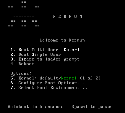
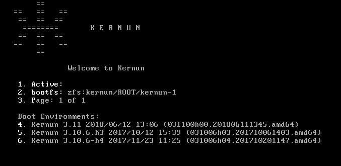
The boot manager displays labels of up to three system
partitions and allows selection of the partition to boot from by pressing
F1, F2, or
F3.
F1 Kernun 3.0 2008/10/01 07:36 (030000h00.200809241501.i386) F2 Kernun 3.0 2008/10/18 05:21 (030000h00.200810170852.i386) F3 Kernun 3.0.1 2008/11/15 07:22 (030001h00.200811142135.i386) Default: F2
If no option is selected, the default one is chosen automatically after a timeout.
Anybody with physical access to the Kernun UTM console may select a system partition to boot from, boot a different kernel or kernel modules, or boot to the single user mode and access the system without a password. If the system console is not physically secure, the following actions can be done to protect the system against unauthorized access:
Disable boot device selection in the BIOS (for example, by setting a BIOS password).
Enable only the desired system partition in the boot manager (using bootmgr(8)).
Add line “
-n” to/boot.config. This prevents interrupting the boot process in the stages one and two.#printf -- '-n\n' > /boot.configProtect the loader with a password by adding a password line to
/boot/loader.conf. Make the file readable only by root.#echo 'password="SECRET"' >> /boot/loader.conf#chmod go-rw /boot/loader.confForce verification of the root password as a condition for entering the single user mode. Locate the line beginning with “
console” in/etc/ttysand change its last word to “insecure”.
Kernun UTM can be installed using either the standalone installer booted from the installation medium, or command line or GUI system management tools. The first installation on a new computer must be done using the standalone installer, which does not require an already installed Kernun UTM with initialized system and data disks and is able to initialize the standard disk layout, as described in Section 2, “Disk Space Layout”. Once there is at least one working Kernun UTM instance on the computer, further installations can by done from it using either the GUI, or the sysmgr command line tool. The standalone installer is able to install in any system partition. The GUI and command line installations cannot be performed in the system partition that contains the currently running Kernun UTM instance.
Note
Regardless of the installation method, the newly installed system partition is, by default, enabled in the boot manager and made the default selection for the next boot. The boot manager can be reconfigured using the GUI or the command line utility bootmgr(8).
The standalone installer is normally used only for the first installation on a new computer, after replacing a disk, or if disk repartitioning is needed. In other situations, installation using the GUI (Section 5.3, “Installation from the GUI”) or the command line (Section 5.4, “Installation from the Command Line”) is more comfortable.
Note
Since version 3.11.7-h3, the installer boots using only UEFI (with disabled Secure Boot), while previous versions used only legacy BIOS. If your hardware does not support UEFI, consider installing an older version and upgrading it to the latest version.
To start the standalone installer, you need the Kernun UTM installation medium[2]. Boot from the USB flash drive and following the boot loader and kernel messages, you will see the installer menu.
*** KERNUN INSTALLATION ***
Build 030000h00.200809241501.i386
1. Install Kernun
2. Check for existing Kernun installations
3. Restore backup
4. Start rescue shell
5. Mount Kernun file systems
6. Resize installer's in-memory temporary file system (current size 32m)
7. Halt
8. Power down
9. Reboot
0. Install license
Select action:
Press 1<Enter>. If the disk partitioning for
Kernun UTM has already been done, the device names of the system and data disks are
displayed and the installer asks whether you want repartitioning.
Detected Kernun system disk ad0 Detected Kernun data disk ad0 Repartition disks (y/n)?
Reply n to skip disk
partitioning. If you reply y or if the disk
partitioning has not been done yet, the system suggests the default
installation:
Default installation parameters: System disk: ada0 (131072 MB) SSD disk: ada1 (524288 MB) Swap size: 8192 MB Install with default parameters? (y/n)
Reply y<Enter> to finish the
installation with default parameters. If you reply n,
the installation parameters are asked. Select the system disk and partitioning
schema:
Detected disk devices: ada0 131072 MB ada1 524288 MB media RPM non-rotating Kernun system disk(ada0 ada1) [ada0]:<Enter>Use ZFS (y/n)y<Enter>
Always select a disk that the BIOS (or UEFI) will be able to boot from as the system disk[3]. If there is only one disk device, the selection of devices will be skipped and the single device will be used. The ZFS partitioning schema is prefered over the legacy (UFS) schema. Note that ZFS boots using UEFI while UFS boots using legacy BIOS.
Tip
When the installer asks a question, it offers a default value
in brackets. Press <Enter> to
select the default value.
The installer then asks for the swap size. Reasonable default value is provided. It can be changed if the default value does not meet the expectations.
System disk size is 131072 MB Memory size is 4096 MB Swap partition size in MB [8192]:<Enter>Disk ada0 [131072 MB] will contain 3 GPT partitions: ada0p1 with freebsd-boot ada0p2 with freebsd-swap [8192 MB] ada0p3 with freebsd-zfs Use these values (y/n)?y<Enter>Disk partitioning will delete contents of selected disks, continue (y/n)?y
If you want to cancel the installation process, answer
n to the last question. It will return to the
main menu without changing the disk contents.
Warning
Answering y to the ``continue'' question will
initialize the selected system and data disks with the standard disk
layout for Kernun UTM. Any existing contents of the disks will be lost.
If there is a SSD disk, it is offered to be used. Select
the device name to use the SSD disk, or select NO
not to use it.
Detected disk devices:
ada1 524288 MB
media RPM non-rotating
Create SSD disk (NO ada1) [NO]: ada1<Enter>
Creating KBI disk on ada1
Messages concerning creation of disk partitions and file systems will then be displayed, followed by:
Current Kernun installations: Boot manager on ZFS pool 'kernun' F1: Unused F2: Unused F3: Unused type=Kernun ZFS boot manager ver. 1.0 current_booted=NONE bootable= update=1 default_selection=NONE Select partition for installation (1 2 3) [1]:<Enter>Overwrite partition /dev/ad0s1 by new Kernun installation (y/n)?y
These lines show the configuration of the Kernun UTM boot manager, see
bootmgr(8). The first installation will be
usually performed in the first system partition, so just press
<Enter>. Finally, you are asked to
confirm whether you want to overwrite the selected system
partition.
The installer creates any missing
standard directories in the data partition, creates a new empty file
system in the selected system partition, and displays a list of the
installation images (identified by build numbers) available on the medium
and in the /data/dist directory. If there is more
than one image, one can be selected, with the
newest image as the default. If the image from the medium is selected, it
is first copied to /data/dist. The selected image
is then unpacked to the system partition. The
/etc/fstab file in the newly installed partition
is adjusted according to the system partition number. The build number
of the installed Kernun UTM is stored in the
/kernun-version file in the system partition. The
content of the newly installed Kernun UTM instance is stored in
/kernun-installed.fsdb.bz2. This file is used by
the backup tools in order to decide which files have changed since the
installation and therefore need to be backed up. After the installation
is finished, the installer waits for
<Enter> and then returns to the
main menu.
...
Available installation images:
1 030000h00.200809241501.i386
Copying installation image to /data/dist
Clearing system partition 1
...
Installing kernun-030000h00.200809241501.i386.txz to system partition 1
Unpacking image
Removing file system content databases for installed images
Creating /etc/fstab
Writing build number into /kernun-version
Creating file system content database
Installation successfully finished
Press Enter for return to menu...Optionally, if you have a license file for your newly installed
system available, you can install it now. This ensures that the initial
configuration script will set the system.product
configuration item correctly after reboot. It will also ask whether the
licensed proxies should be enabled in the initial configuration. The
license installation is done in several steps:
Prepare a USB disk with a UFS or FAT file system.
Copy the license file
license.datto the root directory of the USB disk. Alternatively, if you have some other license files (for example, for the antivirus engine), you can pack them all[4] in thelicense.tarfile in the tar format with all paths relative to the Kernun system root directory.Do not connect the USB disk yet and select
0from the installer main menu.When prompted, connect the USB disk. The license files present will be installed.
Select 9 from the main menu to have the
newly installed Kernun UTM booted. You can then perform its initial
configuration, as described in the following section.
Note
The /data/dist directory may contain full and
patch installation images. A full image can be always installed. A patch
image contains only the differences from a base image. Hence the base image
must be available in order to install the patch image. The base image may
itself be a patch image, and its base image is then required as well. Generally,
each patch image requires a continuous sequence of base images starting
with a full image followed by zero or more patch images.
When a newly installed Kernun UTM system is booted for the first time, an
interactive initial configuration script
(/etc/rc/kernun-config) is executed early in
the boot process[5].
It prompts the administrator for various basic system
parameters, creates and applies the Kernun UTM configuration file, and
finishes the boot procedure with the new configuration. The initial
configuration can be modified later using the standard Kernun GUI or
command line configuration tools.
First, the time zone needs to be set. We recommend to use UTC for
the CMOS clock—select Yes by pressing
<Tab><Enter> in
the first dialog.
Even if the CMOS clock is currently set to the local time, it is
better to select UTC here and adjust the time later using the
date(1) command or by configuring NTP,
see section ntp in
system(5). After selecting the CMOS clock
mode, the time zone menu is displayed. Choose the time zone suitable for
your location. Then set the administrator password
(user root).
After that, a new SSH host key is generated. It is used to authenticate the system to a remote access client[6] (GUI or command line SSH). You should write down the reported key fingerprint and compare it with the fingerprint reported by SSH or the GUI when making the first remote connection to the system. The SSH host keys should be the same for all Kernun UTM installations on the same computer. Therefore, if an SSH host key exists during the installation, it is copied to the newly installed system partition and the generation of a new key is skipped during the initial configuration. The GUI and command line installers look for an SSH host key in the current system partition. The standalone installer takes an SSH host key from the first system partition that contains one and is different from the partition, in which the installation is taking place.
Answer n to the following question (or
just press <Enter>) if you
want to input the basic configuration parameters and generate the
initial Kernun UTM configuration file.
**********************************************************************
Fingerprint of the SSH host DSA key. Compare this value with the value
reported by SSH client or Kernun GUI when connecting in order to check
that you are connecting to this system.
1024 71:0a:ec:8d:dd:9e:e7:2d:2b:91:79:0e:1a:ca:89:2b
/etc/ssh/ssh_host_dsa_key.pub
**********************************************************************
*** KERNUN INITIAL SYSTEM CONFIGURATION ***
Skip Kernun configuration (y/n)? [n] <Enter>Two network interfaces are configured in the default configuration: internal, intended to be connected to the protected network, and external, which is typically connected to the Internet. The configuration script asks for the names, IP addresses, and network masks of these interfaces. Then, the DNS server and default router addresses need to be specified. The initial configuration will allow the administrator SSH access from the internal network (using the GUI or a command line SSH client). If you want to allow some application protocols to pass from clients in the internal network to servers in the external network, you can enable the respective proxies. The configuration of the proxies will contain the default values of various parameters, which will be sufficient for the simplest use. More complicated configuration requirements can be implemented later by editing the generated initial configuration file using the GUI or command line configuration tools (modifying proxy configuration, adding new proxies, etc.). An example of the initial configuration setup is given and explained below.
Caution
In many environments, an initial configuration with enabled proxies may violate a security policy. Therefore, it is recommended not to enable any proxy in the initial configuration unless you are sure that you really need it.
Hostname without domain []:fwDomain []:
example.comShow only Ethernet interfaces (y/n)? [y]By repeating the following test with connected and disconnected network cables, you can determine interface names of physical network cards. *** Media state of network interfaces *** ed0: media: Ethernet autoselect (100baseTX <full-duplex>) ed1: media: Ethernet autoselect (100baseTX <full-duplex>) Show again (y/n)? [y] *** Media state of network interfaces *** ed0: media: Ethernet autoselect (none)
ed1: media: Ethernet autoselect (100baseTX <full-duplex>) Show again (y/n)? [y] *** Media state of network interfaces *** ed0: media: Ethernet autoselect (100baseTX <full-duplex>) ed1: media: Ethernet autoselect (100baseTX <full-duplex>) Show again (y/n)? [y]
nInternal interface name (ed0 ed1) []:ed0Internal IP address []:
192.168.10.1Internal interface netmask [24]: External interface name (ed0 ed1) []:ed1External IP address []:
192.168.11.2External interface netmask [24]: DNS server IP address []:10.1.1.1Default router IP address []:
192.168.1.1Postmaster e-mail [postmaster@example.com]:
Enable some proxies (y/n)?
yEnable DNS proxy (y/n)? [n]
yEnable FTP proxy (y/n)? [n] Enable HTTP proxy (y/n)? [n] Enable HTTPS proxy (y/n)? [n] Enable POP3 proxy (y/n)? [n] Enable IMAP4 proxy (y/n)? [n] Enable SMTP proxy (y/n)? [n] Enable SSH proxy (y/n)? [n]yHostname: fwDomain: example.com Internal interface: ed0 Internal IP: 192.168.10.1 Internal netmask: 24 External interface: ed1 External IP: 192.168.11.2 External netmask: 24 Name server: 10.1.1.1 Default router: 192.168.11.1 Postmaster e-mail: postmaster@example.com Enabled proxies: DNS SSH Use these values (y/n)?
y
The configuration begins with
setting the host name and the domain name. Then, the internal and external
interfaces are selected. First, the available network interfaces are listed.
You can choose whether you want to show all
interfaces, or just Ethernet interfaces. The interfaces are repeatedly
listed with their media states. This can be useful if you are not
sure about the names of physical interfaces. You can unplug network cables
one by one and observe, which interface changes its state. In the example
, the cable was unplugged from the network
interface ed0. The internal and external interface
names, IP addresses, and network masks are defined. The DNS server IP
address is used by Kernun UTM for domain name
resolution. The default router is typically
a router in the external network. The postmaster e-mail address is used by the SMTP proxy to forward mail sent
to the postmaster.
You can also enable some proxies for
access from the internal to the external network. Questions about
individual proxies are asked only if you reply y to
the initial “enable some proxies” query. Otherwise, all proxies
are disabled without further questions. The generated initial
configuration file will contain configuration of the disabled
proxies as well, with their configuration sections marked as hidden. A proxy
can be easily enabled later by unhiding its configuration using the
GUI or the command line configuration interface. Only licensed proxies are
offered for enabling.
Finally, all values defined during the configuration setup are listed
. If you are satisfied, reply
y and the initial
configuration file will be generated and applied. If you reply
n, the whole configuration setup will be repeated
with the previously specified values as defaults.
After defining values for the initial configuration, the SSH key for remote administrator access is generated. You must enter a passphrase used to encrypt the key. The same passphrase is also used for the initial download of the key from Kernun UTM.
The configuration script will now generate the root's SSH key. The passphrase for the key will be also used as the password for initial key download from Kernun GUI. Enter SSH key passphrase: Repeat SSH key passphrase: Generating public/private dsa key pair. Your identification has been saved in /home/keygen/id_dsa. Your public key has been saved in /home/keygen/id_dsa.pub. The key fingerprint is: 33:27:5a:63:53:b1:ba:47:bf:e8:58:4a:d0:f6:d4:d4 root@fw.example.com
The SSH key generation is the last step in the initial configuration process. After that, the normal operation of the newly installed Kernun UTM begins.
The SSH (private) key needs to be downloaded to the administrator's
local computer and subsequently copied to any system used by the
administrator to access Kernun UTM. The administrator's computer must be
in a network routed via the Kernun UTM internal interface, e.g.,
192.168.10.0/24 in our
configuration example. There is a special user account keygen dedicated to SSH key download. The
GUI is able to download the key automatically, you only need to select
Initialize new firewall in the Connect to
Server dialog. See also Section 1.1, “Kernun GUI Launcher” for
details. For command line SSH access, you can either use the key
downloaded by the GUI, or download the key manually:
Use SCP to copy the private OpenSSH key (
id_dsa), the public OpenSSH key (id_dsa.pub), and the Putty key (key.ppk).$scp keygen@192.168.10.1:* .keygen@192.168.10.1's password: id_dsa 100% 736 0.7KB/s 00:00 id_dsa.pub 100% 609 0.6KB/s 00:00 key.ppk 100% 807 0.8KB/s 00:00$Log in to Kernun UTM as user
rootusing the newly obtained key.$ssh -i id_dsa root@192.168.10.1Enter passphrase for key 'id_dsa': ...[root@fw ~]#Delete the key files in the home directory of user
keygen.[root@fw ~]#rm ~keygen/*Disable the
keygenaccount.[root@fw ~]#pw lock keygenLog out from Kernun UTM.
[root@fw ~]#logoutConnection to 192.168.10.1 closed.$
The steps after the first one are not strictly necessary, but they are
recommended for security reasons. Although the secret SSH keys are
protected by a passphrase, they should be kept in a secure store that
can be accessed only by authorized administrators. If the key is downloaded by
the GUI, the key files on Kernun UTM as well as the
keygen account are automatically
removed when the GUI connects to Kernun UTM with the downloaded key for
the first time.
In this section, we assume that the reader has at least the
basic knowledge of the Kernun GUI. An introduction to the Kernun GUI can be
found in Section 1, “Graphical User Interface” of this manual. The installation and
its related tasks are controlled by the Kernun GUI System
Manager, which is accessible using the

The installation is done from the Installation
images tab in the System Manager window, see Figure 2.4, “Installation images in the System Manager”. It displays a list of available
installation images (stored on Kernun UTM in
/kernun/dist). An image is marked as
installable if it is either a full image, or a patch image with an
available base image. The version number, build date, and build
number are listed for each image. Installation images can be copied
from the administrator's local machine, where the GUI runs, to
Kernun UTM by clicking the button.
The button can be used to copy
in the opposite direction. It is also possible to
delete a selected image () or all
images older than the selected one[7] ().
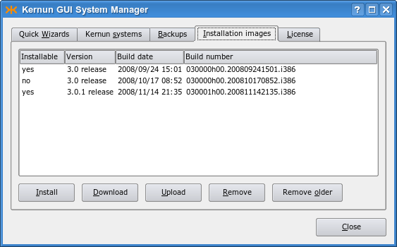
Tip
Each installed image is is copied to
/data/dist. As the images may consume a lot of
disk space on a regularly updated Kernun UTM, it is recommended to
delete old images regularly or when you need more space on the data
disk. An easy way to do this is to select one of the newest images
and click .
It is usually sufficient to retain only the one or two most recent
images.
To initiate the installation of the selected image, click the button. In the example, we will install the newest (last) installation image from the list. The installation of Kernun UTM can be alternatively initiated using the button on the Quick Wizards page. A wizard window (see Figure 2.5, “Selection of the installation target”) appears and prompts you to select the target system partition. It displays the number and label of the system partition that contains the currently running system. This partition cannot be overwritten by the installation. One of the other two system partitions, which are also listed with their labels, needs to be chosen. If you started the wizard from the Quick Wizards page, you are then supposed to choose the desired installation image. Finally, the recapitulation of the selected values is displayed. Click the button to launch the installation process (it deletes all the existing content of the selected partition).
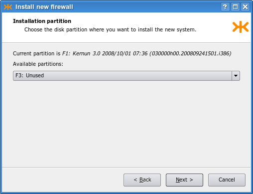
Caution
When performing an installation, make sure that you have selected the correct system partition, in order to avoid inadvertently overwriting a system partition that you want to retain.
The installation process takes several minutes; it can be aborted using a button in the progress dialog displayed in the meanwhile. The newly installed system partition is made bootable, but the default boot partition is not changed. The reason is that the new Kernun UTM instance is not configured and until its initial configuration is performed from the console, it will be inaccessible via the network. The boot manager configuration after the finished installation can be viewed in the System Manager's Kernun systems tab, as shown in Figure 2.6, “The system partitions after the installation”. It is possible to change the partition label (using the button) or make the new system partition the default boot partition (the button).
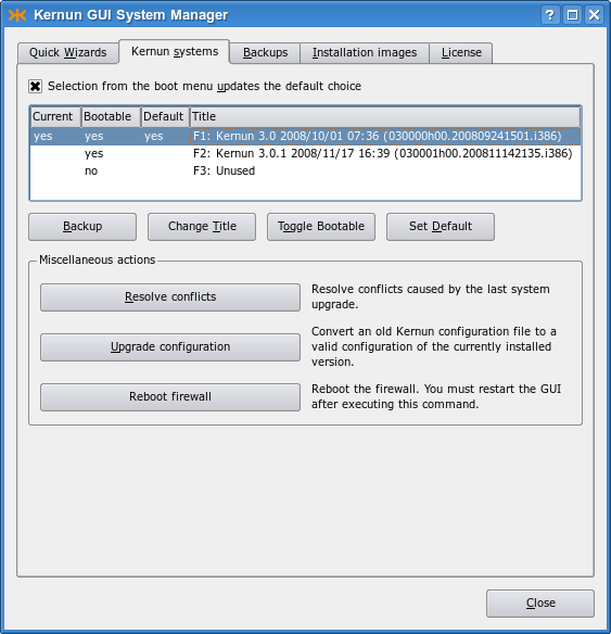
If the installation process terminates because of an error, the output of the failed command is displayed. The example in Figure 2.7, “An error during the installation” shows an error message caused by a corrupted installation image file.
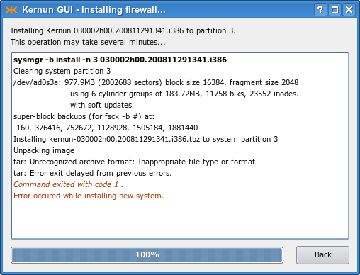
The command line installation functionality is provided by
the
sysmgr(8) and
bootmgr(8) utilities. An installation
image that is to be installed must be stored in the
/data/dist directory, along with the
corresponding base image(s), if it is a patch image. The existing
images can be listed using the following command:
[root@fw ~]#sysmgr images* 030000h00.200809241501.i386 030000h00.200810170852.i386
The installable images are marked with an asterisk. The image
is a patch image that cannot be installed,
because its base image is missing. Information about the currently installed
instances of Kernun UTM can be obtained using the
bootmgr command or from the
/kernun-version file. In order to get access to this
file in other system partitions, the file systems in those partitions
need to be mounted first.
[root@fw ~]#bootmgrBoot manager on /dev/ad0 F1: Kernun 3.0 2008/10/01 07:36 (030000h00.200809241501.i386)[root@fw ~]#cat /kernun-version030000h00.200809241501.i386[root@fw ~]#mount /2[root@fw ~]#cat /2/kernun-version030000h00.200810170852.i386[root@fw ~]#mount /3mount: /dev/ad0s3a on /3: incorrect super block
The bootmgr command displays labels of the
system partitions and the number
of the system partition that contains the currently running system
. The second system partition in
the example contains another Kernun UTM version , even though it was manually relabeled as
“Unused”. The third system partition is really unused;
it does not even contain a file system .
We will install a new Kernun UTM version in the second system partition. We choose the newest version available according to the sysmgr images report. Unlike the standalone installer described in Section 5.1, “Standalone Installer”, the command line installer asks no questions. The image build number and the target system partition number are given on the command line and the installation starts immediately. The standard partition label, containing the Kernun UTM version, date of installation, and build number, is set for the newly installed partition. The initial configuration process (see Section 5.2, “Initial Configuration”) is started after booting from the newly installed system partition.
[root@fw ~]#sysmgr install 2 030001h00.200811142135.i386Clearing system partition 2 ... Installing kernun-030001h00.200811142135.i386.txz to system partition 2 Unpacking image Installing SSH host keys Removing file system content databases for installed images Creating /etc/fstab Writing build number into /kernun-version Creating file system content database Installation successfully finished[root@fw ~]#bootmgrBoot manager on /dev/ad0 F1: Kernun 3.0 2008/10/01 07:36 (030000h00.200809241501.i386) F2: Kernun 3.0.1 2008/11/17 16:39 (030001h00.200811142135.i386) F3: Unused type=Kernun 1024 B boot manager (74 character labels) current_booted=1 bootable=1 2 update=yes default_selection=F2
Caution
Be careful when running sysmgr install. Especially, make sure that you specify the correct system partition number. Otherwise, you might inadvertently overwrite a system partition that you would like to retain.
Caution
The newly installed system partition is made the
default choice for the next boot. As it is not configured, it will
be inaccessible via the network after the reboot and its initial
configuration will need to be performed from the console. If you want to
keep the current default boot partition, so that you retain a fully
working system after the reboot, use the -n
parameter of the sysmgr command:
[root@fw ~]#sysmgr install -n 2 030001h00.200811142135.i386
Typically, the interaction with Kernun UTM is performed using a VGA console. However, in some cases it is neccessary to switch the system output to a serial console, which is also available on most of Kernun devices. In order to redirect the output to a serial console, plug-in the console to a serial port, restart Kernun UTM, and follow these steps:
Press <Space> repeatedly until the booting process prompts with
boot:When the prompt
boot:appears, type “-h” and confirm by pressing<Enter>. The output of booting proccess should now be redirected to the serial console and continue.>> FreeBSD/i386 BOOT Default: 0:ad(0,a)/boot/loader
boot:-h
Kernun UTM provides both GUI and command line tools used to back up
system partitions and restore data from backups created in this way.
They can be used to back up not only the current system partition, but
any of the three system partitions. A backup file does not contain
the complete contents of a system partition, but only the changes made
since its installation. The size of the backup file therefore depends
on the amount of changes that have been made in the system partition
since its last installation. After an installation, the content of a
system partition is stored in the
/kernun-installed.fsdb.bz2 file. When doing
backup, this file is compared with the current content of the system
partition. Added and modified files are stored in the backup file,
along with information about deleted files and files with changed
metadata attributes[8].
The backup and restore operations process only a subset of files
contained in a system partition, mainly Kernun configuration files.
The list of files included in a backup can be viewed and modified
in the /etc/kernun-fsdb-include file. During
backup and restore operations, this file is passed to
diskdb(1)
using the -I parameter.
Backup files are stored in the /data/backup
directory, from which they should be copied to a safe place.
They should not be renamed, because their names contain
important information for backup processing: the build number of
the Kernun UTM instance, the number of the backed up system partitions,
and the date and time when the backup was created.
A backup created on a particular Kernun UTM version (build number) should
be restored to a system partition containing a newly installed image with
the same build number. On the other hand, a system partition with any
partition number can be used for restoring, not only the one where the backup
was created. The restore program adjusts the contents of the file system table
/etc/fstab accordingly.
Kernun UTM provides tools for manual backup and
restoring of system partitions using local backup files in
/data/backup. The administrator should create a backup
at least after every major configuration change and copy it to a storage
medium other than a local disk. Solutions for automated backup, remote backup,
or backup of the data partition are not provided out of the box, because
backup policies required for different deployments vary significantly.
More sophisticated backup scenarios can be implemented using
operating system tools
(tar(1),
cron(8), etc.) or various third-party
backup software. The Kernun UTM tools support only complete restoring of
a backup to a newly installed system partition. Nevertheless, a backup file is a
tar(1) archive compressed by
bzip2(1) and can therefore be freely
manipulated using these tools.
In some situations, especially when a backup is restored to a different version of Kernun UTM or to a system partition that has been modified since the installation, conflicts may be reported during restoring. It is also possible that unresolved conflicts from an earlier restore operation interfere with the current one. In such a case, the old conflicts need to be resolved or discarded first. See Section 7, “Upgrade” for explanation of conflicts and instructions on how to resolve them.
A backup can be created in the GUI in the Kernun
systems tab of the System Manager (Figure 2.6, “The system partitions after the installation”). All you need to do is select a system partition
and click on the button. A backup file will be
created and stored in /data/backup. The new
backup will appear in the Backups tab, see Figure 2.8, “Existing backup files in the GUI”. Using buttons under the list of backup files,
a file can be downloaded to the administrator's computer, uploaded
back to Kernun UTM, or removed.
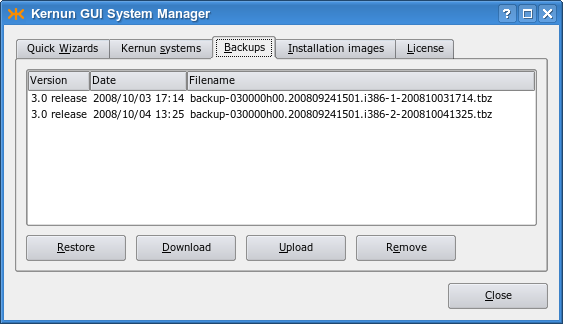
Click on the button if you want to start the restore operation. Alternatively, restoring can be initiated using on the Quick Wizards page. A wizard window appears. It prompts for the target system partition (must not be the currently booted one), for selection of a backup file and for a corresponding installation image. There are also buttons for uploading a locally stored backup or image to Kernun UTM. As the last step, the recapitulation of the selected values is displayed, as shown in Figure 2.9, “Parameters of a restore operation”. When you click , the selected image is installed in the chosen system partition and the selected backup is unpacked. Then it is possible to do any combination of the following operations: set the newly restored partition as the default boot partition; change the partition label; reboot Kernun UTM immediately (see Figure 2.10, “Final settings after restoring a backup”).
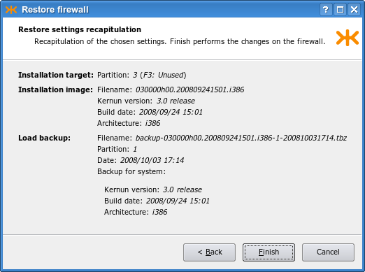
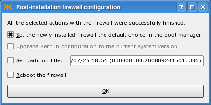
The
sysmgr(8) utility is used to create
and restore backups from the command line. A new backup file in
/data/backup is created by the following command:
[root@fw ~]#sysmgr backup 2Creating backup content database /kernun-backup.fsdb.bz2 Creating file system content database Creating backup file /data/backup/backup-030000h00.200809241501.i386-2-200807281400.tbz[root@fw ~]#
If a backup of the current system partition is to be created, the
partition number (2 in our example) may be
omitted. A list of existing backup files is displayed by
[root@fw ~]#sysmgr backupsbackup-030000h00.200809241501.i386-1-200810031714.tbz backup-030000h00.200809241501.i386-2-200809261822.tbz backup-030000h00.200809241501.i386-2-200809301350.tbz
A backup can be restored to a selected system partition; it must not be the currently used system partition. A clean installation of an image with the correct build number should be done first.
[root@fw ~]#sysmgr install 2 030000h00.200809241501.i386... Installation successfully finished[root@fw ~]#sysmgr restore 2 \>backup-030000h00.200809241501.i386-1-200810031714.tbzProcessing changes of file system contents Unpacking files from backup Resolving conflicts All conflicts resolved[root@fw ~]#
An attempt to restore a backup in a system partition that contains a Kernun UTM instance with a different build number is detected and a warning is displayed:
[root@fw ~]#sysmgr restore 2 \>backup-030000h00.200809241501.i386-1-200810031714.tbzBackup is from different build than currently installed in /2. Installed: 030001h00.200811142135.i386 Backup: 030000h00.200809241501.i386 It is strongly recommended to restore a backup to the Kernun build that was used for creating the backup. Continue anyway (y/n)?n[root@fw ~]#
A backup can be restored also from the standalone
installer booted from the Kernun UTM installation medium. This can be helpful
after installing a new system disk or when moving a Kernun UTM installation
to a new computer. First, select a system partition and install Kernun UTM
from an image corresponding to the backup that is to be restored,
following the procedure described in Section 5.1, “Standalone Installer”.
If the backup file is not already located in /data/dist,
you can copy it there using the emergency repair environment
tools, as described in Section 9, “Emergency Repair Environment”.
*** KERNUN INSTALLATION *** Build 030001h00.200811142135.i386 1. Install Kernun 2. Check for existing Kernun installations 3. Restore backup 4. Start rescue shell 5. Mount Kernun file systems 6. Resize installer's in-memory temporary file system (current size 32m) 7. Halt 8. Power down 9. Reboot 0. Install license Select action:1Detected Kernun system disk ad0 Detected Kernun data disk ad0 Repartition disks (y/n)? n Current Kernun installations: Boot manager on /dev/ad0 F1: Kernun 3.0 2008/10/01 07:36 (030000h00.200809241501.i386) F2: Kernun 3.0.1 2008/11/17 16:39 (030001h00.200811142135.i386) F3: Unused type=Kernun 1024 B boot manager (74 character labels) current_booted= bootable=1 2 update=yes default_selection=F2 Select partition for installation (1 2 3) [1]:3Overwrite partition /dev/ad0s3 by new Kernun installation (y/n)?yAvailable installation images: 1 030000h00.200809241501.i386 2 030001h00.200811142135.i386 Select image to install (1-2) [2]:1Enter the label that will be used to identify this installation in the boot manager. The label can be at most 44 characters long. The Kernun build number will be appended after the entered label automatically. Label [Kernun 3.0 2008/11/20 10:26]: Clearing system partition 3 ... Installing kernun-030000h00.200809241501.i386.txz to system partition 3 ... Installation successfully finished Press Enter for return to menu... *** KERNUN INSTALLATION *** Build 030001h00.200811142135.i386 1. Install Kernun 2. Check for existing Kernun installations 3. Restore backup 4. Start rescue shell 5. Mount Kernun file systems 6. Resize installer's in-memory temporary file system (current size 32m) 7. Halt 8. Power down 9. Reboot 0. Install license Select action:3Select partition to be restored (1 2 3) [1]:3Available backups for build installed in partition 3: 1 backup-030000h00.200809241501.i386-1-200810010405.tbz 2 backup-030000h00.200809241501.i386-1-200810040604.tbz Select backup to restore (1-2) [2]:1Restoring backup-030000h00.200809241501.i386-1-200810010405.tbz to partition 3 Are you sure (y/n)?yConflicts resolution data in /data/restore already existyProcessing changes of file system contents Unpacking files from backup
In the example above, we assume that the backup file is already
stored in the /data/backup directory and the corresponding
installation image in the /data/dist directory. We
start the backup restoring procedure by carrying out a fresh Kernun UTM
installation in an unused system
partition . The installation image is chosen so that it corresponds to the
backup file that will be restored. After returning to the installer
main menu, we select
. The partition installed in the previous step should be
selected. A list of backups compatible with the content of the target
system partition is displayed. We choose one of the offered backup
files and the restoring begins. The
message indicates that there are
unresolved conflicts from previous restore or upgrade operations.
Usually, you should reply n to the question
. This will interrupt the
restore operation. You can restart it after you resolve the conflicts
according to instructions given in Section 7, “Upgrade”. If you are
sure that you do not need to resolve the old
conflicts[9], you may reply
y and the conflict resolution data will be
deleted. The message and question concerning the old conflicts
will not be displayed if there are no pending conflicts. Finally , the backed up files are unpacked from the backup
file and checked for conflicts. No conflicts should occur if the
backup is restored to the same Kernun UTM build that was installed at the time
the backup was created. The restored files are installed in their
proper places and the restore operation successfully finishes.
The upgrade procedure described in this section is applicable if you want to retain as much as possible from the configuration of the old Kernun UTM instance in the new instance. If you want to configure a new Kernun UTM version from scratch, follow the installation and configuration procedures described in Section 5, “Installation”.
Upgrading to a new version or build of Kernun UTM is basically done by restoring a backup of the old version in a system partition that contains a fresh installation of the new version. The upgrade procedure comprises the following steps:
The syntax and semantics of the configuration files are sometimes slightly changed between versions. In order to be usable in the new Kernun version, the old configuration file must be converted in step 1. This is done automatically during the upgrade process. The configuration conversion script expects the configuration in a normalized format. Using just some formatting accepted by normal Kernun configuration tools (GUI or CML) is not sufficient. The normalization during the upgrade process is done either automatically (by GUI), or using a command in the command line upgrade.
Important
If you are upgrading from a Kernun version that does not implement automatic configuration normalization during the upgrade process, that is, from a version older than 3.3.2, you should perform the normalization manually. It can be done simply by opening and saving the configuration by either GUI, or CML. The normalization step may be skipped if the configuration has been saved recently and has not been modified outside the Kernun configuration tools, for example, by a text editor.
The upgrade operation results in a newly installed system partition
that contains the new version of Kernun UTM. If we want to keep the configuration
across upgrades, we need to copy the main Kernun UTM configuration file
/usr/local/kernun/conf/kernun.cml and any other
changes done in the old installation to the new one. The configuration files
that have been changed, created, or deleted since the installation are
found and saved when the old system partition is backed up in
step 2.
Step 3 requires a full or patch installation image. Although it is possible to replace the contents of the currently used system partition with the new version, it is not recommended. You should always install an upgrade to a currently unused system partition, for two reasons. First, the old Kernun UTM instance can continue running until the upgrade is finished. Second, you can quickly return Kernun UTM to an operational state if something goes wrong with the upgrade.
Tip
The recommended practice is to use two system partitions for regular upgrades. One partition is occupied by the currently running version, while the other contains the old version and will be used for installation of the next upgrade. After each upgrade, the roles of the two partitions are switched. The third system partition can be reserved for special tasks, such as preparation of a completely new configuration.
Tip
Set the boot manager (as described in Section 4, “Boot Manager”) default boot partition so that it always boots the currently used Kernun UTM instance. Consider disabling the automatic updating of the default boot partition or disabling the unused partitions altogether.
Restoring of the backup from step 2 in the system partition installed in
step 3 effectively copies the
complete configuration from the old system partition. Restoring of a backup
to a build different from the one used for its creation may cause
conflicts. These are files that cannot be restored
automatically and a manual intervention of the administrator is necessary.
A conflict occurs if there are two incompatible changes of the same file.
The original version of the file comes from the installation image of
the Kernun UTM instance that is being upgraded; we will call it “old”. The
second version (called “backed-up”) is contained in the backup file,
if the file was changed[10] at some time between the installation of the old
version and the start of the upgrade process. The third version
of the file (called “new”) is obtained from the installation image of
the new Kernun UTM instance installed in step 3. There are two potential changes of the
file. One between the old and the backed-up version, the second between
the old and the new version. If only one change exists, no conflict occurs
and the changed (backed-up or new) version of the file will be used. For
example, /etc/ttys may have been
changed by the administrator in the installed Kernun UTM, but remains the same in
the build we are upgrading to. Another example is a proxy executable,
which is modified in the new Kernun UTM version, but left unchanged by the
administrator. If all three versions exist, i.e. when the backed-up
and the new version differ, a conflict occurs. The automated upgrade tools
are unable to handle the file and the administrator must decide whether
the new file, the backed-up file, or some combination of the two should be
used. For example, a third party software added in the new build
creates a new user account in /etc/master.passwd, and the
administrator has created another user account. During the upgrade, a conflict
is reported for /etc/master.passwd. The administrator
can resolve this particular conflict by merging the two versions of the file,
adding both new user accounts to the resulting file.
The detected conflicts are recorded in the
/data/restore/resolve file during step 4. The conflicting files from the backup
file (the “backed-up” version) are not unpacked to the
root directory tree. Instead, they are stored in corresponding locations
under the /data/restore/conflicts directory. The root
directory tree contains the files as installed (the “new”
version). In step 5, the
administrator specifies for each file how the conflict should be resolved,
choosing from the following possibilities:
The new version is retained and the backed-up version is deleted from
/data/restore/conflicts.The backed-up version replaces the new version.
The new or the backed-up version is used, but is modified first, for example by merging the contents of the two versions in a text editor.
The conflict is postponed until a later iteration of conflict resolution.
The /data/restore directory is deleted when all conflicts
are resolved. Only one upgrade procedure can be in the conflict resolution
stage at a time. If a conflict resolution session is started and there is
already the /data/restore directory with unresolved
conflicts, the administrator can either cancel the second resolution, or
delete the old /data/restore directory, thus effectively
using the “new” versions of the files for all conflicts in the earlier
conflict resolution session.
In step 6, a script is executed
that edits the contents of the main configuration file
/usr/local/kernun/conf/kernun.cml to make
it compatible with the upgraded Kernun UTM. Sometimes, if there
are complex changes in the configuration syntax and semantics between
the two Kernun UTM versions, or if the configuration file contains certain
advanced constructs, the script may be unable to perform a perfect
conversion. It is therefore recommended to always check the result of the
automatic conversion in step 7.
The new configuration file needs to be applied before the upgraded system can be put into normal operation. The low-level configuration files are generated and the configuration is applied in the context of the newly installed system using the applycfg command of sysmgr(8). If the generation or application of the configuration fails, the configuration should be corrected and applied again.
Finally, the upgraded Kernun UTM can be put into the normal production mode by rebooting to the newly installed system partition.
No modifications of the configuration (steps 6 and 7) are often required during the upgrade procedure. This is usually true when upgrading between two builds of the same version or between patch releases of the same version, for example, from 3.0 to 3.0.1 or from 3.0.1 to 3.0.2.
An upgrade is initiated from the Quick Wizards page of the System Manager. There are two alternatives. Click if you want to start the complete upgrade procedure. If you already have a recent backup of the system partition that you want to upgrade, you can skip the first step — creation of a backup. In this case, use the button. We will describe only the former alternative; the latter is almost identical, only the backup step is missing.
The GUI assumes that we want to upgrade the currently running Kernun UTM instance. Therefore, the current system partition will be backed up. After clicking on the button, we select the target system partition in which the upgraded Kernun UTM will be installed. Then we select the installation image of the new version. Our selections are displayed in the settings recapitulation window (Figure 2.11, “Parameters of an upgrade operation”). Click on the button to start the upgrade.
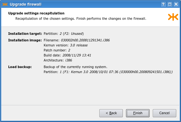
The GUI displays the progress of the upgrade procedure. First, the current system partition is backed up. Then, the new system partition is installed and the backup is restored in it. If there are any conflicts, the conflict resolution window is displayed, as shown in Figure 2.12, “The conflict resolution window during an upgrade”. The window shows a list of conflicting files. You can determine how to resolve the conflict of a file by clicking in the Action column. The following actions are possible:
+— uses the “backed-up“ version of the file;.— uses the “new” version of the file, as installed from the new installation image;-— deletes the file;!— postpones the conflict to the next iteration of conflict resolution.
It is also possible to select a file and then click a button on the right-hand side of the window to display the differences between the two versions of the file, or to open one of them in an editor.
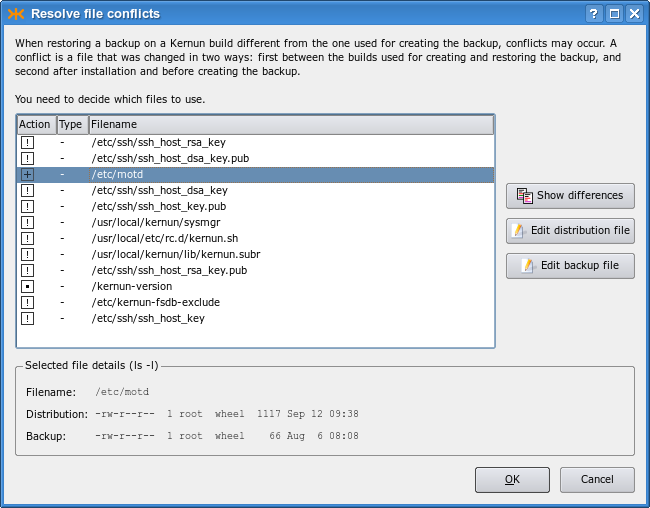
After you give instructions for conflict resolution and optionally edit some conflicting files, click to have the conflicts resolved. Finally, a window is displayed (see Figure 2.13, “Final settings after an upgrade”) that makes it possible to realise any combination of the following actions: set the newly upgraded system partition as the default boot partition; run the configuration conversion script; change the partition label; reboot Kernun UTM immediately.
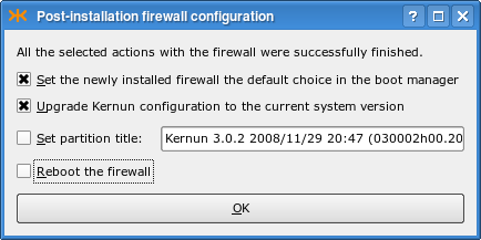
Command line upgrades are realized using the sysmgr(8) utility. Unlike when using the GUI, which performs all the required steps automatically, a command line upgrade must be done step by step. An example of the upgrade procedure follows:
[root@fw ~]#cml -l -f /usr/local/kernun/conf/kernun.cmlRCSL-730-N File '/usr/local/kernun/conf/kernun.cml' locked for current user CMLM-790-N RCS command completed[root@fw ~]#sysmgr checkcfg... Configuration is correct[root@fw ~]#sysmgr backupCreating backup content database /kernun-backup.fsdb.bz2 Creating file system content database Creating backup file /data/backup/backup-030000h00.200809241501.i386-1-200811300006.tbz[root@fw ~]#sysmgr install 2 030002h00.200811291341.i386Clearing system partition 2 ... Installation successfully finished[root@fw ~]#sysmgr upgrade 2 \>backup-030000h00.200809241501.i386-1-200811300006.tbzProcessing changes of file system contents Unpacking files from backup Resolving conflicts There are pending conflicts, see /data/restore/resolve *** CONFLICT RESOLUTION ***2# Conflict resolution file for system partition /2[root@fw ~]#vi /data/restore/resolve...[root@fw ~]#sysmgr resolveResolving conflicts All conflicts resolved[root@fw ~]#sysmgr upgradecfg 2Upgrading Kernun configuration /2/usr/local/kernun/conf/kernun.cml /2/usr/local/kernun/conf/kernun.cml,v <-- /2/usr/local/kernun/conf/kernun.cml new revision: 1.2; previous revision: 1.1 done Automatic configuration upgrade done. It is recommended to review the configuration before returning Kernun UTM to production use.[root@fw ~]#sysmgr applycfg 2... System kernun applied in system partition 2
[root@fw ~]#cml -u -f /usr/local/kernun/conf/kernun.cmlCMLM-790-N RCS command completed[root@fw ~]#
Before upgrade, the configuration should be locked
[11], checked and
normalized . This step ensures that
the configuration upgrade step will
understand the configuration file. The upgrade procedure starts by
backing up the current system partition .
Specify a system partition number to upgrade a currently
inactive partition. If a recent backup already exists, this step can
be skipped. A new Kernun UTM version is installed to an unused system
partition . This command also sets
the default boot manager label for the newly installed partition, and
makes it bootable and the default boot selection for the next booting.
The backup is then restored to the newly installed system partition
. This command writes the list of
conflicts to /data/restore/resolve. The
conflicting files from the backup are stored in the
/data/restore/conflicts directory. If there are
conflicts, the conflict resolution menu is displayed . You can either resolve the conflicts,
or postpone the conflict resolution to do it later. If you choose
to resolve the conflicts, the conflict resolution file
/data/restore/resolve is opened in a text editor.
Edit the file according to the displayed instructions to determine the way of resolution
of individual conflicts. After the file is saved and the editor is
terminated, the conflict resolution is executed in accordance with
the file. If some conflicts remain unresolved, a message is printed. It is then possible to
edit /data/restore/resolve manually and restart the conflict resolution
. Commands and can be repeated until all
conflicts are resolved. The main configuration file is
upgraded and applied . Finally, the lock is released  . You can then reboot to
the new system partition and start using the upgraded Kernun UTM.
. You can then reboot to
the new system partition and start using the upgraded Kernun UTM.
The Kernun auditing tool kernun-audit(1) provides a convenient source of information about bugs discovered in the Kernun software. The auditing tool also reports when a new software version becomes available. A Kernun audit is usually executed daily by the cron daemon via the periodic command. It downloads the up-to-date auditing database, and then examines the product type, version, and architecture of the installed system. Based on these values, the relevant records are extracted from the database and reported. There are two classes of records: bugs and software updates.
Each bug that is discovered in the currently installed version of the Kernun product is reported. A bug has a unique identification number, a description, a list of versions, in which it occurs, a solution, and a workaround. The recommended solution is always a software update to a version in which the bug has been fixed (if such version is available). The workaround (if available) describes how to minimize the impact of the bug without updating the software. It should be applied if the software has not been fixed yet or if an immediate update is infeasible. Nevertheless, the workaround should always be regarded as a temporary solution and the Kernun installation should be updated as soon as possible.
Software updates are reported only for the same product and architecture as in the installed system. The latest patch release from each release branch is shown. Only versions newer than the currently installed version are displayed. For example, if 3.1 is the version installed and 3.0–3.0.6, 3.1–3.1.3, and 3.2–3.2.1 are available, 3.1.3 and 3.2.1 will be the versions reported.
The initial configuration of a Kernun system runs the auditing tool
daily using the DEFAULT-CRONTAB and
DEFAULT-PERIODIC variables from the
included crontab and the periodic configuration file
crontab.cml. Auditing can be disabled by setting
daily_status_security_kernun_audit_enable to
"NO" in that file. The auditing tool
kernun-audit can be also executed manually from the
command line. The product name, version number, and architecture name are
obtained from the current system, or can be specified using the command line
arguments of kernun-audit. The identification of the
current system is stored in the files /kernun-product
(product name) and /kernun-version (build number,
which contains the version number before the first dot and the
architecture name after the second dot). If the location (local or remote)
of the audit database is not specified, the database is downloaded from
download.kernun.com by
default.
The www.kernun.com Web
site provides an online version of the Kernun auditing tool. After filling
the Kernun product, version, and architecture in a form, the auditing report
is generated in the same format as the one kernun-audit
produces.
Warning
The instructions in this section are intended for experienced administrators with profound knowledge of Kernun UTM and FreeBSD.
The Kernun UTM installer booted from the installation medium can be used to repair the system if all system partitions are unable to boot. The available functions are accessible from the installer main menu:
1. Install Kernun 2. Check for existing Kernun installations 3. Restore backup 4. Start rescue shell 5. Mount Kernun file systems 6. Resize installer's in-memory temporary file system (current size 32m) 7. Halt 8. Power down 9. Reboot 0. Install license
Option 1 is described in
Section 5.1, “Standalone Installer”. Options 7,
8, and 9 are
self-descriptive. Option 2 displays the boot manager
configuration and the disk device names.
System disk is /dev/ad0 Boot manager on ZFS pool 'kernun' F1: Kernun 3.11 2018/06/06 07:36 (031100h00.201806111345.amd64) F2: Unused F3: Unused type=Kernun ZFS boot manager ver. 1.0 current_booted=NONE bootable=1 update=1 default_selection=F1
Option 3 restores a backup selected from a list
of backup files found in /data/backup. If the backup
is stored on another medium, it must be first copied to the
/data/backup directory, using for example the rescue shell
(option 4). For details about backup and restoring, see
Section 6, “Backup and Restoring”.
Option 4 starts a rescue shell
(bash). It provides the environment for emergency
maintenance of a computer with non-bootable Kernun UTM installations. The
rescue shell (as well as the whole standalone installer) runs in a custom
FreeBSD environment. The standard Kernun UTM kernel is used. The root file
system is mounted from the installation medium and is therefore read-only.
A read-write RAM disk for temporary data is mounted under
/tmp, symlinked also from
/var/tmp. The standard size of the RAM disk is
32 MB. It can be resized using option 6 of the
installer main menu.
Warning
The content of the RAM disk is lost when the installer is terminated or when the RAM disk is resized.
Caution
Do not make the RAM disk too large, because its content is stored in the kernel memory. If the free kernel memory gets too low, the kernel may panic.
Option 5 of the menu mounts any existing Kernun UTM
partitions under the directories /1,
/2, /3 (the system partitions),
and /data (the data partition). The rescue shell
provides many standard FreeBSD command line programs. Programs from a mounted
Kernun UTM system partition can be run as well.
Tip
It is often useful to perform a chroot(8) to a mounted Kernun UTM system partition and to run commands in the chrooted environment.
Kernun can be deployed in any virtualization environment with support for FreeBSD OS.
See also the notice in Section 24, “High Availability Clusters”.
The following virtualiztion environments are tested for compatibility with Kernun.
The emulators/open-vm-tools-nox11 is installed and staretd automatically if the VMWare environment is detected.
The virtualization support is built in the FreeBSD OS. See also https://docs.microsoft.com/cs-cz/windows-server/virtualization/hyper-v/Supported-FreeBSD-virtual-machines-on-Hyper-V and https://wiki.freebsd.org/HyperV for more detailed information.
The emulators/virtualbox-ose-additions is installed and started automatically if the VirtualBox environment is detected.
[1] Collect values from lines
starting with component:, group:, and
upgrade: in the license file.
[2] You can use dd
on Linux / BSD or
ImageWriter on Windows to copy the USB flash drive image
to the device.
[3] It is usually the first disk: da0
(SCSI), ad0 (PATA), ad10
(SATA).
[4] including
usr/local/kernun/license.dat
[5] More precisely speaking, the initial
configuration script is executed during any system boot if there is no
Kernun UTM configuration file
/usr/local/kernun/conf/kernun.cml and none of
the files /etc/rc.conf and
/etc/rc.conf.local contain the line
kernun_config_enable=NO.
[6] The host key is used by the SSH client (or GUI) to ensure that it is communicating with the intended server. It is different from the client's key, which is used to authenticate the client to the server.
[7] An image is considered older if it has a lower version number or an earlier build date.
[8] for example, access rights, owner, or modification time
[9] for example because they are in a system partition that is not used any more
[10] By a change, we mean modification of the contents of the file, deletion of the file, a change of the file attributes (e.g., the owner or access rights), or creation of a previously nonexistent file.
[11] Steps and
are supported by Kernun since
release 3.6. In the prior versions, these steps should be
skipped.
Kernun UTM can be administered locally, or remotely via the network. Local administrator access is usually limited to the initial installation, when the network is not yet configured, and emergency situations after a failure or misconfiguration if the network is not accessible. The administrator can access the system locally via a text system console. It provides the same set of command line tools as the remote text login via SSH. In normal operation, Kernun UTM is usually administered remotely. There are two options for remote access: a text command line interface and a graphical user interface.
An administrator can log in to Kernun UTM remotely via SSH and get shell access to the system. Administrative tools accessible from the shell include the primary Kernun UTM command line control and configuration tools kat(8) and cml(8), see also Section 2, “Command Line Interface”. Besides these two, many additional command line utilities are available, including specific Kernun UTM commands introduced in Section 3, “Administrative Utilities” and all the standard FreeBSD commands.
Kernun UTM's graphical user interface (GUI for short, described in Section 1, “Graphical User Interface”) provides a similar functionality as the command line utilities, but in a more intuitive and comprehensive way. It shows the current state of all system components and can display details for each component. The GUI contains also a powerful log analyzer, a configuration editor, and a system manager, which administers installations, backups, and upgrades. There is some functionality that is unique to the GUI and cannot be accessed from the command line, such as displaying of performance graphs. The GUI runs on the administrator's local computer and communicates with Kernun UTM via the network, using SSH internally. Hence, the same prerequisites are needed for both the command line and GUI access to Kernun UTM (especially, SSH keys and the SSH protocol enabled on the way between Kernun UTM and the administrator's computer).
In this section, we will introduce the Kernun GUI. In later chapters dealing with configuration (Chapter 4, Configuration Basics, and Chapter 5, Advanced features) we will assume that the administrator knows how to use the GUI.
The Kernun GUI is available in two functionally equivalent versions: for Microsoft Windows and for UNIX. The binary executables of the Kernun GUI are distributed for MS Windows and for FreeBSD [12]. The Kernun GUI can be easily compiled also for other UNIX platforms. See the README file for instructions on how to compile the Kernun GUI.
On UNIX machines, the Kernun GUI expects OpenSSH to be installed
(namely, the ssh, ssh-agent,
ssh-keygen and ssh-add programs are
expected to be located in a directory listed in the PATH
environment variable).
There are no prerequisites to be installed on MS Windows. All the necessary executables are included in the Kernun GUI distribution.
The Kernun GUI provides the following functionalities:
monitoring of the state of Kernun UTM;
management (starting, stopping, restarting, …) of Kernun UTM (or its particular components);
work with logs (both current online logs and downloaded offline logs) and statistics;
modification and application of the configuration of Kernun UTM;
administration of Kernun UTM installations, backups, and installation images.
When the GUI is started, the launcher window is displayed, see Figure 3.1, “GUI Launcher”. The launcher provides buttons to open (and change) a local copy of the Kernun UTM configuration file (for more information on work with the configuration in the GUI see Section 1.4, “GCML — Configuration”) or examine a local log file (see Section 1.3, “Logs”). However, the main purpose of the GUI launcher is to establish a new connection to Kernun UTM and launch the main GUI management window.
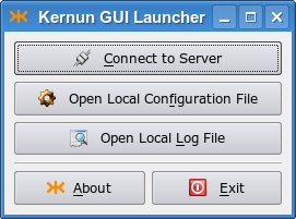
The GUI communicates with Kernun UTM via
SSH connections. You therefore need to have the
sshd service running and correctly
configured (see Section 2.3, “SSH Server”).
The parameters of the SSH connection to Kernun UTM are specified in the
Connection Parameters dialog, as depicted in Figure 3.2, “Connecting to Server”. You need to fill in the
Host name or IP address of the Kernun UTM machine,
Username, Port and select the
SSH key file.
Tip
If you are connecting to Kernun UTM via SSH for the first time, you need to initialize Kernun UTM (i.e., download your private SSH key from Kernun UTM). To do this, use the dialog that appears after the button is pressed. Fill in the Hostname and the Password you entered during the installation. See also Section 5.2, “Initial Configuration”.
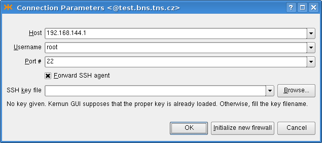
If you intend to apply the configuration to other Kernun UTM than the one you are logged in (for example, the second Kernun UTM in a cluster), you must check the Forward SSH agent check box. See ssh(1) for information about security risks of SSH agent forwarding.
Important
It is unsafe to leave the SSH keys loaded in the ssh-agent after finishing your work with Kernun UTM.
The key is deleted automatically on
UNIX, if there was no
ssh-agent running before the Kernun GUI was started.
Otherwise, you need to unload it yourself (e.g. using
ssh-add -d private_key_file).
On MS Windows, the Kernun GUI instances are managed by the GUI launcher, which is set to unload the keys automatically (after a timeout) if there are no main Kernun GUI applications running. You can change this behavior or unload the key manually using the context menu of the Kernun GUI taskbar icon.
The functionality of the Kernun GUI main window, depicted in Figure 3.3, “GKAT — Kernun UTM management console”, is basically equivalent to the command line administrative tool kat(8). It displays the states of individual Kernun UTM components and allows them to be started, stopped, and monitored.
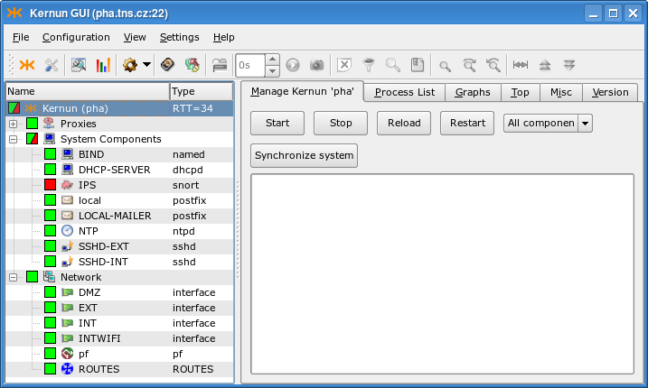
When connected to Kernun UTM, the state of the proxies and other
system components is indicated
by their state icons. The states of the components are also
propagated to the state icon of their parent component groups and of
the whole Kernun UTM. There are the following component groups:
Proxies, System Components
(such as SSH servers, mail forwarders, or DNS servers),
Network (interfaces, packet filtering, routing),
and Open VPN servers.
A running component is denoted by green icon background ![]() , whereas the background of a stopped component
is red
, whereas the background of a stopped component
is red ![]() . There are several icon overlays that
indicate further information concerning the component's state:
. There are several icon overlays that
indicate further information concerning the component's state:
 Not up-to-date configuration — the
configuration of the component has changed; reload it, so that the changes
can take effect.
Not up-to-date configuration — the
configuration of the component has changed; reload it, so that the changes
can take effect.
 Parent exiting flag — the proxy is in a special state: it
does not accept new connections, but only waits for the already active sessions to finish.
For example, this state may appear when a proxy is reloaded, some sessions
remain open in the old proxy instance, and only the new instance accepts
new connections. Total restart of the proxy stops the old proxy instance and
starts another, so no sessions remain open.
Parent exiting flag — the proxy is in a special state: it
does not accept new connections, but only waits for the already active sessions to finish.
For example, this state may appear when a proxy is reloaded, some sessions
remain open in the old proxy instance, and only the new instance accepts
new connections. Total restart of the proxy stops the old proxy instance and
starts another, so no sessions remain open.
 Not in configuration — the system component
is not in the configuration. Kill the component to solve the problem.
Not in configuration — the system component
is not in the configuration. Kill the component to solve the problem.
 Component's state changing — this overlay
is displayed while the component's state (started/stopped/restarted/reloaded) is being changed.
It disappears immediately after the action is finished.
Component's state changing — this overlay
is displayed while the component's state (started/stopped/restarted/reloaded) is being changed.
It disappears immediately after the action is finished.
In the situation depicted in Figure 3.3, “GKAT — Kernun UTM management console” we know that all proxies are running, even though the Proxies subtree is collapsed. The IPS component is stopped, which is why the System Components and Kernun icons are partially green and red. Kernun UTM has four network interfaces, the packet filter and the routing table running. No Open VPN server is configured. You can click on a component, group, or the whole Kernun UTM icon in the proxy tree to select it and display its details in the right-hand part of the window. The information about the RTT (Round Trip Time) in milliseconds between the GUI and Kernun UTM is displayed next to the Kernun UTM name.
On the Manage page of the whole Kernun UTM (that is, with the top-level Kernun node selected from the component list in the left-hand part of the window), the administrator can easily manage (start/stop/reload/restart) the whole Kernun UTM, as depicted in Figure 3.4, “Kernun UTM Manage Page”.
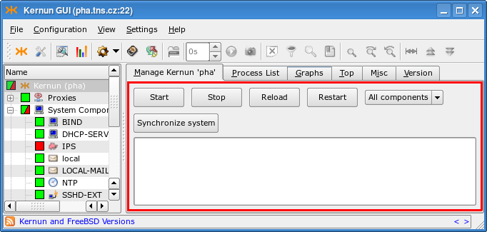
The selected action can be applied either to all components, or to the components marked with a tag in the configuration. The tag or the All components option can be selected from a combo box. A change in the configuration takes effect only after the system state is synchronized with the updated configuration. This can be always done by rebooting, restarting, or reloading the whole Kernun UTM, but it often suffices to restart only a subset of components, while the remaining parts of Kernun UTM may be left running. The Synchronize system button automates this process. It displays a window (depicted in Figure 3.5, “System state synchronization dialog”) that lists the actions required to bring all the components into sync with the configuration. You can manually alter the proposed actions by clicking on a component in the Action column. When you are satisfied, click and all the selected actions will be executed.
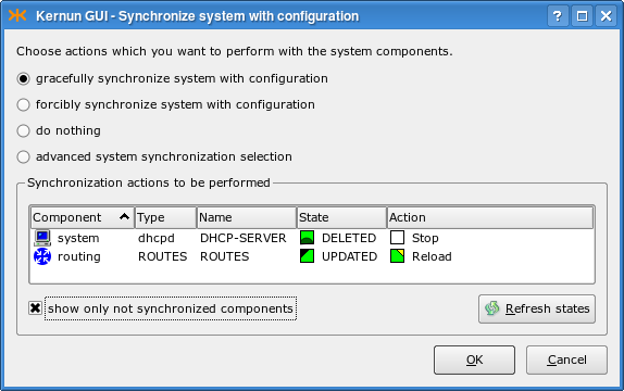
The Process List page (Figure 3.6, “Process List page”) contains the list of the running parent proxy processes[13].
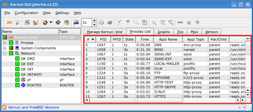
The context menu in the process list
(Figure 3.7, “Process List context menu”) can be used to send the TERM
(Kill parent process) or KILL
(Kill -9 parent process)
signals to the particular process, to copy the contents of
the process list to the clipboard or to save them to a file.
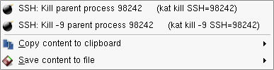
The Graphs page contains graphs of various system parameters, see Figure 3.8, “Graphs page”. There are many monitored parameters of the operating system (CPU load, used memory and disk space, etc.), hardware (temperature measurement, if supported by the hardware), and cluster behavior (switches between the cluster master and backup). Kernun UTM collects parameter values and creates graphs depicting how they evolve in time, with several time scales available. The most detailed graphs show only the recent history, while coarse-grained graphs extend further into the past. Right-click on a graph to open a context menu that makes it possible i.a. to save the graph to a file or to add it to Favorite graphs.
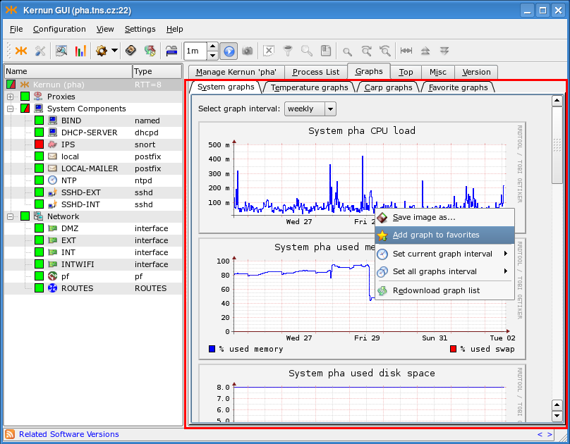
The Top page (Figure 3.9, “Top page”) shows the output of the popular top(1) command. The Misc page (Figure 3.10, “Misc page”) displays the output of several commands, showing i.a. the disk space (the df -hi command), the network state (netstat) or the uptime and current load of Kernun UTM (w | head -n 1). The Version page (Figure 3.11, “Version”) shows the version of Kernun UTM and of the FreeBSD system used by Kernun UTM.
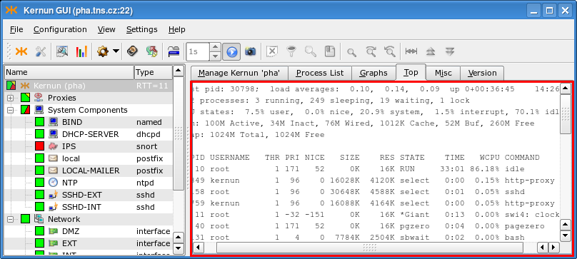
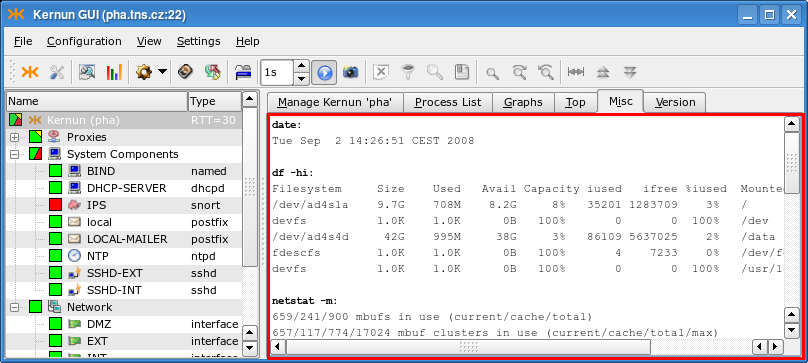
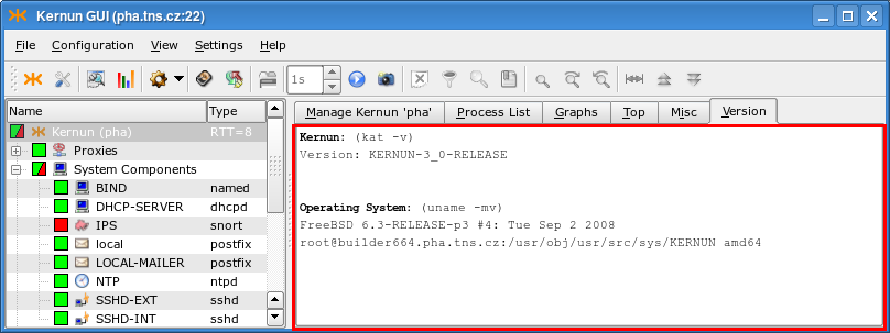
When the Proxies node or a particular proxy is selected in the component tree, it is possible to control and monitor all proxies or the single proxy, respectively. The set of pages is similar in both cases, but the Process List and Graphs pages are available only if a single proxy is selected.
The Manage page for all proxies is similar to the Manage page of the whole Kernun UTM (Figure 3.4, “Kernun UTM Manage Page”), but the button and the combo box used to restrict operations to the tagged components are missing. For individual proxies, there are three additional buttons. terminates the proxy like , but works also for proxies that are removed from the configuration. The and buttons change the log level. For more information about log levels, see logging(7).
The Process List page contains the list of running processes, restricted to the processes that belong to the particular proxy; both parent and child processes are listed. The functionality is identical to the global process list (Figure 3.6, “Process List page”), including the possibility to send signals to processes.
The Monitor page, see Figure 3.12, “Proxy Monitor”, shows the current active sessions of all proxies, or of the selected proxy. Its content is available only for proxies, for which monitoring(5) is enabled in the configuration. Proxies can be configured to generate the monitoring information into different directories, so it is possible to select the directory, from which the GUI will read the monitoring data.
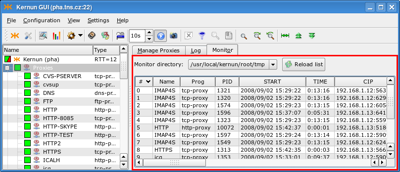
The Graphs page's functionality is similar to the system-level one shown in Figure 3.8, “Graphs page”, but different graphs are displayed: the number of proxy child processes and the number of bytes transferred by the proxy.
The Log page shows the current log messages of the selected proxy, or of all proxies. New messages are added immediately, so the log view provides information about the current proxy activity. Select from the context menu in the log view to open the Details window with a reference page containing information about the selected message. Click on the Row Detail tab in the Details window to display the message as a whole, rather than split into fields. Figure 3.13, “Proxy Log” shows the log page with the Details window displayed.
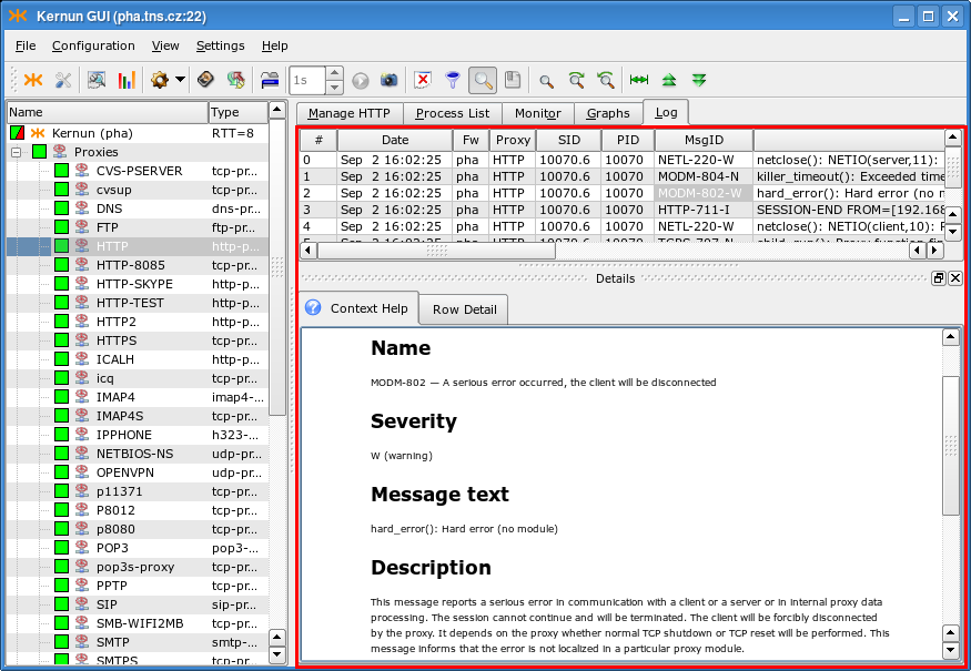
The Network node in the component tree groups individual network interfaces, the routing table, and the packet filter[14].
All nodes in the Network subtree share the Manage page containing buttons for starting/stopping/restarting/reloading a component, similar to that of the whole Kernun UTM, as depicted in Figure 3.4, “Kernun UTM Manage Page”, but without the Synchronize system button and the component tag selection combo box. Other pages differ for various types of nodes in the Network component subtree. For the Network node, individual network interface nodes, and routing there are pages containing output of the ifconfig(8) and netstat(8) commands with various parameters. The Network node provides an additional page sockstat -4 with the list of all existing IPv4 sockets. Each network interface has a Graphs page with traffic statistics graphs in bits and packets per second. Otherwise, the page behaves like its system-level counterpart (Figure 3.8, “Graphs page”). The current configuration and state table of the packet filter node can be displayed using pages containing the output of the pfctl(8) command.
The toolbar and the menu of the main GKAT window contain almost identical sets of actions. They are adapting to the currently displayed components (page) of the application, i.e., only the useful (and usable) buttons or menu items are enabled.
Figure 3.14. Main window toolbar buttons, listed together with the corresponding menu items, and sometimes keyboard shortcuts:

— Shows the about dialog box with information about the GUI version.
— Opens the basic preferences dialog, in which you can set the default behavior of your GUI (e.g., your default diff program).
<Ctrl+L> — Opens a form, in which you can choose certain restrictions of the log information to be analyzed (date, time, proxy, etc.), and then downloads the log from Kernun UTM and displays it in a new window (for more information on log analyzing see Section 1.3, “Logs”).
— Opens a proxy statistics browser window. If configured, daily, weekly and monthly statistics of traffic handled by proxies are computed from the log. The browser window displays a hierarchy of available statistics ordered first by the frequency (weekly/monthly/daily), then chronologically, and finally by the proxy name. After choosing an item from the hierarchy, the corresponding statistical output (in the form of a HTML document with images containing graphs) is displayed.
The submenu:
— Downloads the Kernun UTM configuration and opens a window, in which you can edit it (see Section 1.4, “GCML — Configuration”).
— Lets you choose and edit a sample Kernun UTM configuration that you can later use as your Kernun UTM configuration.
— Opens a local configuration file for editing. You can later upload it to your Kernun UTM to use it as its configuration or save it back to your computer.
— Opens an RCS Browser displaying all the changes you have made in the Kernun UTM configuration and making it possible to switch back to any of the previous versions.
The submenu:
— Opens the console with an ssh connection to Kernun UTM.
— Opens a dialog, in which you can create custom remote commands that can be executed in the console. When created, they are added to the menu and can be easily invoked.
— Provides routines to install, backup, and upgrade Kernun UTM installations. See Section 5, “Installation”, Section 6, “Backup and Restoring”, and Section 7, “Upgrade” for details. The system manager has also the License page, accessible also from . It displays the current license file and provides a button for uploading a license file to Kernun UTM.
— Restarts the connection from the GUI to Kernun UTM. It may be useful if your RTT gets too high or the connection is interrupted.
<Ctrl+T> — Opens the current page in a new window and keeps it up-to-date (refreshes the selected page).
Refresh Frequency — The period, with which new data is downloaded from Kernun UTM. The lower is the period, the more traffic load Kernun UTM produces towards the GUI.
Start/Stop — Starts and stops refreshing (downloading of new information from Kernun UTM) of the current page.
— Makes a static copy of the current page and opens it in a new window. This window is never refreshed. It can be used to analyze the snapshotted situation (e.g., the traffic log).
— Clears the contents of the current page.
<Ctrl+M> — Shows or hides the Filters and Markers window, which is used to specify filtering and marking for the displayed log (see Section 1.3, “Logs”).
<Ctrl+D> — Shows or hides the details window, which displays the details of the current row (e.g., in a log) and the reference page for the current row type.
<Ctrl+B> — Shows or hides the bookmarks window. Bookmarks are used to assign a name to a certain line of a snapshotted situation. You can then easily jump from one bookmarked line to another.
<Ctrl+F> — Opens a dialog used to search for selected text in a selected column. The view highlights all the found occurrences and jumps to the first one.
<Ctrl+G> — Jumps to the next line marked by the chosen marker.
<Ctrl+Shift+G> — Jumps to the previous line marked by the chosen marker.
<Ctrl+I> — Adjusts the column widths according to the widths of their contents.
<Ctrl+Up> — Scrolls to the beginning of the current page.
<Ctrl+Down> — Scrolls to the end of the current page and keeps scrolling so that the newly added lines are displayed. This function is most useful with the Log page, if we want to display newly added messages continuously.
The Kernun GUI contains a powerful log analyzer. It provides tools for filtering out undesired log entries and for marking those that are more important to you with different colors. The log window (possibly displayed as a part of another window) is displayed in several modes: you can either open a local log file, download a “historical” log file from Kernun UTM, take a snapshot of the currently displayed log, or work with the up-to-date (and changing) log.
The first setting concerning logs is the specification of the log level for the particular proxy (permanently in the configuration or temporarily using buttons on the Manage page). There are seven different log levels, as described in logging(7). The higher the level is, the more information the Kernun UTM stores (and sends to your log analysis window).
Figure 3.15, “Example of a simple HTTP filter and marker set” shows an example of a log display window (created by selecting in the GKAT main menu). The logs are presented as tabular data. You can drag a column by its title and drop it elsewhere to change the column order. Each column has a context menu used to select which columns are to be displayed. For example, if you are analyzing a log from a particular proxy in a single Kernun UTM network, you may want not to display the columns Fw (Kernun UTM name), Proxy and PID (as the PID is also included in the column called SID, which is a concatenation of the PID and the number of the current session[15] served by this process). You can use the Save column visibility settings option, so that you do not have to set it every time.
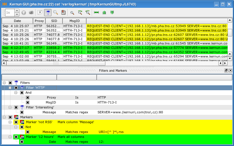
The filters and markers are accessible using (<Cltr+M>). Filters are used to display only the log entries that you are interested in, while the main point of markers is to highlight some special rows (columns) in the log. A selected marker can be then easily used to jump to the next/previous marked line.
Note
Both filters and markers are managed (created, deleted, moved, changed) in a similar way. From now on we will only describe management of filters. However, all of the operations work in the marker context, too.
The only difference between the management of filters and markers is that markers are applied automatically after a change, whereas filters need to be explicitly applied by selecting the option from the context menu of the Filters node, or by clicking on the same button, which appears blinking after any change in the filter set. Moreover, the context menu of a marker contains an option used to change the highlighting color and highlighted column(s).
Important
If you work with the current live log, the filters only apply to the newly incoming log messages. The old ones are not filtered out even if you apply the filter. To filter out older log entries, tear off a snapshot. Markers take effect instantly in all situations.
There can be many filters in the system. They are all presented in the filter tree under the Filters node. Some of the filters may be turned off (by unchecking the box next to their name). Each filter is a tree of conditions with logical operators And, Or and Not. Each condition consists of a column to be examined, a relational operator and a desired value. The relational operator defines the relation between the value in the column and the desired value that must be fulfilled in order for the row to be included in the log. The following relational operators are available: Is, Contains, Matches regex and their negations, Starts with and Ends with; they are all self-explanatory.
The easiest way to create a filter is to drag and drop a field from the log table. A new filter is created and a new condition inside this filter is initialized with the value of the field you dropped there. You can also drag a field and drop it on the relational operator (then the new condition is added as a child of the operator) or on another condition (in this case, you are asked whether you want to use And or Or to connect it with the target condition or whether you want to add the new condition to the same parent). Other useful options (including creation of a new filter) are listed in the context menu of the selected node of the filter tree.
Having created some filters, you can copy a particular node (and all its subnodes) to another place simply by dragging it there. In this way you can easily create a filter from an existing marker, and vice versa.
You may want to save filters you create for future use. You can save a single filter or any subset of filters. Both saving and loading of filters is done using the context menu of the chosen filter (or the Filters node). A filter can be saved either to a local file, or to the registry. The filters (and markers, of course) in the registry are displayed in (and can be loaded from) the submenu of the top-level Filters/Markers context menu.
Tip
To rename a filter/marker, double-click on its name or select from the context menu.
This section describes the GUI functionality for examination and modification of the Kernun UTM configuration. It does not describe the configuration language. See Section 1, “Configuration Language” for an introduction to the configuration syntax and semantics, and Section 2, “The Initial Configuration” for a simple configuration example.
Kernun GUI provides a GUI editor for the Kernun UTM configuration
files (kernun.cml
Figure 3.16, “GUI CML Editor” shows the main GUI configuration window. The configuration is displayed in an expandable configuration tree. You can select a node to display and easily edit its details in the right-hand part of the window. The displayed details include the selected node's type and name, its full path in the configuration (as displayed by cml(8) in the command line prompt), a brief description, and the constraints (if there are any). There is also a form with fields (editable, if appropriate) that represent the elements of the selected node. A short description, the name of the element, and the expected data type are displayed to the right of each field. The labels of the required fields are highlighted (bold). Several field types help you fill in data of the correct data type. If you make a mistake (e.g., do not fill in all the required information or do not respect the expected data type) the background of the incorrect field is highlighted, an exclamation mark button appears next to it (click on the button to show the error message) and the error is also displayed in the configuration tree.
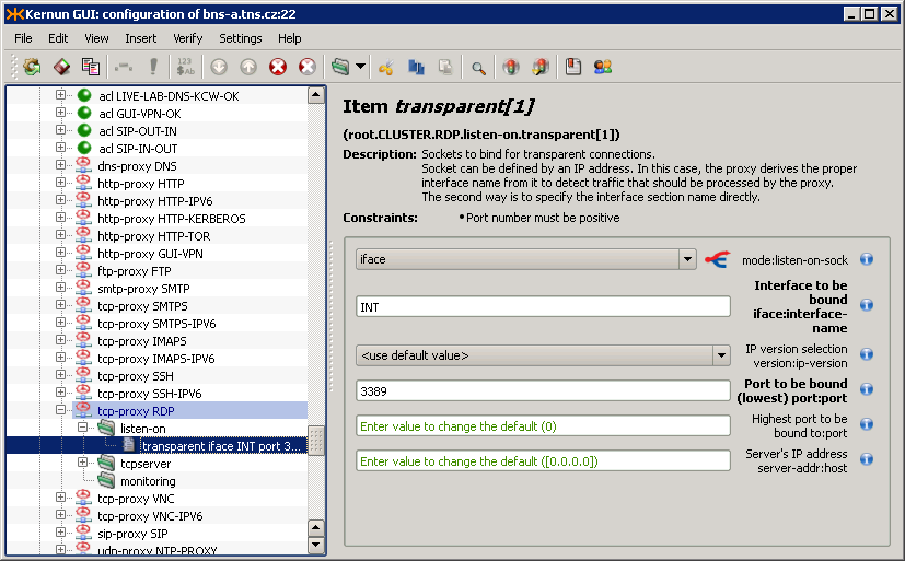
When editing the configuration, select in the main menu to display the differences between the current contents of the configuration and the original configuration file downloaded from Kernun UTM. The currently edited configuration can be saved to a local file using the menu item. In addition to online marking of incorrect configuration nodes, it is possible to invoke verification of the whole configuration using .
When you finish editing of the configuration, you may want to save and apply it to Kernun UTM or save it as a local file. Both can be easily done using the menu. Committing of the configuration (<Ctrl+S>) invokes a dialog, depicted in Figure 3.17, “Configuration commit dialog”, where you can choose actions to be done with the configuration on Kernun UTM (save/generate/apply/synchronize state, all done by default) and the configuration to apply. The results of the action are displayed in a text box. If you have made any changes to the configuration, you are asked to fill in the RCS Log Message describing the changes. First, the configuration file is saved and stored in a RCS file, in which the complete history of changes is kept and from which any old version of the configuration file can be retrieved. Then, low-level system and proxy configuration files are generated. The application of the configuration means copying the low-level configuration files to locations, in which Kernun UTM components look for them at the startup. Finally, the system state is synchronized with the configuration. This is the same action as the one performed by , including the possibility of reviewing and modifying the list of performed actions in the dialog window shown in Figure 3.5, “System state synchronization dialog”.
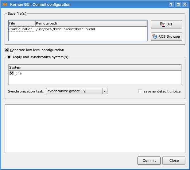
Each line of the configuration tree represents a node of the Kernun UTM configuration and has an icon according to its type. You can select a node by clicking on its name. The easiest way to move in the tree is using the cursor keys. <Up>/<Down> selects the next/previous node, <Right> expands the current section, <Left> jumps to the parent of the current node (or collapses an expanded section). A non-empty section node can also be expanded/collapsed by clicking on the +/- sign next to it. Useful commands for interaction with the configuration tree are available in the menu, the context menu of the selected node, and on the toolbar. A section can be expanded, along with all of its subsections (and their subsections, etc.) by selecting <Ctrl++> (and collapsed using the <Ctrl+-> command). Because the order of individual sections and items matters, you can move a node up and down (<Ctrl+Up>/<Ctrl+Down>) using commands from the same menu. You can also (<Ctrl+D>), (<Ctrl+H>), (<Ctrl+C>), (<Ctrl+X>) or (<Ctrl+V>, pastes the last copied/cut node under the selected one) a node.
Tip
If you are more familiar with the line-oriented cml(8) tool, you may want to see the text version of the configuration of the current node (section). This is accessible from the menu or from the context menu of the node. A read-only window containing the output of the /show -a cml command is displayed.
Inserting a new node using the
menu is relatively easy with the GUI.
First, you need to decide where you want to add the new node
(as the first child, as the last child (<Ins>), or next
to the current node (<Ctrl+I>)). Then you need to
choose the type of the new node (section, item, data variable
definition, section variable definition, section variable application,
for loop, switch/case, include file, or comment).
In the case of inserting a section, item or section variable, you need to
choose the type of the section/item and its name (if appropriate).
Finally, the new node is inserted and you can edit its properties in
the details window.
Several form field types are used to represent the properties of a node. It is important to understand each of them, in order to fill in correct data.
Text box — Expects text data. However, you cannot fill in anything; you still need to preserve the data type specified in the parentheses in the field label (e.g., the sock type means
[). The syntax of values of various data types used in the Kernun UTM configuration is described in Section 1, “Configuration Language”.ip]:portCheck box — Can either be checked (true), or unchecked (false).
Combo box (selection) — You can choose exactly one of the specified options. If you want to enter its content manually, you need to use the menu item, which allows you to write there “anything” (e.g., a variable name). If there is a “fork” icon next to the combo box, the value of the combo box decides which further form fields are displayed (e.g., in
system.smtp-proxy.delivery-acl.senderthe error value requires further constraints on the error, whereas the ok option does not).List of values — Some CML properties (e.g.
system.acl.service) expect a list of values of a certain type (str, addr…). You need to be able to create new values, as well as change and delete the old ones. The value list field type displays each value of the list in a separate row. You can simply edit a particular value in the same way as you are used to work with the above-mentioned field types. A value can be deleted from the list using the icon next to it. To insert a new value, click the button. The value lists can be multidimensional (any value list can contain sublists, which can also contain sublists, etc.). You can append a new sublist by clicking the button. On the right from a sublist there is a button with a submenu that allows to or (creates the negation of the current sublist). List items can also be loaded from a file, in which each line represents one item of the list. To “inject” a file into a list, click on the button and select theshared-filesection name, in which the file name and the format (e.g., IP addresses, text or REGEXPs) are specified.
Tip
The contents of the shared-file can be
edited in the GUI in the details of the path item of
the shared-file section.
As orientation in a very big configuration may become difficult, the Kernun GUI provides tools to simplify it.
First of all, you can use (<Ctrl+B>) to create bookmarks (like in your Web browser) to important positions in the configuration tree. The bookmark window is displayed in the top right part of Figure 3.18, “Bookmarks and relevant sections in GUI CML”. To add a bookmark to the current configuration node, select the option from its context menu or the option from the context menu of the bookmark list in the Bookmarks window. You are asked to fill in the bookmark's title before adding it. You can jump to a bookmarked node by double-clicking the bookmark's name in the Bookmarks window. Additional bookmark operations (removing, renaming) are available from the context menu of individual bookmarks.
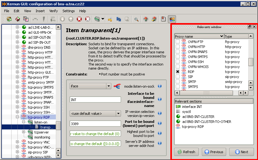
In addition to simple bookmarks, the Kernun GUI provides smart bookmarks, accessible via (<Ctrl+R>). Smart bookmarks are used to highlight the configuration nodes that are relevant to the chosen nodes (e.g., the ACLs for proxies) and to easily jump to them. The function of finding and highlighting of the relevant nodes is only available for proxies (it would not make much sense for other nodes), but the relevant nodes may include any sections (proxies, ACLs or other sections). A node is relevant to a proxy if a change to the node may alter the behavior of the proxy.
There are two lists of bookmarks in the Relevants window. The first one (Proxies) displays the list of all proxies in the configuration and makes it possible to select the proxies, for which the relevant nodes are to be highlighted. The other list (Relevant sections) displays bookmarks to configuration nodes that are relevant to the chosen proxies. Again, you can double-click a bookmark to jump to it in the configuration tree. After selecting the proxies in the Proxies list, the relevant nodes are highlighted in the configuration tree and bookmarks to them are displayed in the relevant sections list.
There are more actions available from the context menus of the items of the bookmarks lists, including (which adds the current item to the simple bookmarks), (works like double-clicking on the item), and several default selection templates for the proxies. Furthermore, you can choose the types of relevant nodes that you are interested in for the Relevant section items.
Tip
You might not want the relevant item list to be to refreshed automatically (after every change in the configuration and in the selection of the proxies), especially on a slower machine. This behavior can be controlled from the context menu of any of the relevant items using the check box in its context menu. If it is unchecked, you have to refresh the list manually by clicking the button.
The Kernun GUI provides configuration wizards in order to simplify the configuration of complex tools (OpenVPN, IPSec). All the wizards are accessible via the menu item. Select to open a dialog that describes all the wizards and the use of the created part of the configuration, and makes it possible to start the selected wizard.
Each wizard is divided into several pages that prompt the user to fill in individual fields. The form fields are the same as in the GCML, so you can use references to other parts of configuration or data variables. The fields highlighted with orange background are filled incorrectly and you need to correct their values before you are allowed to proceed. The last page of each wizard displays the part of the configuration that has been created using the wizard and the result of verification of the configuration after the changes are committed into the configuration. If you do not like the values, you can return back in the wizard, correct the respective fields and proceed to the wizard overview again. When you finish the wizard, the created configuration is committed to the main system configuration. You can cancel the wizard at any moment to undo all the changes and return back to the GCML.
The Help button located on each wizard page opens a help window next to the current page that describes all the fields on it. The contents of the help window always correspond to the current page.
Tip
All that can be created using wizards can be done also manually using the standard GCML interface. Another option is to create only the core part of the configuration using the wizard and then modify it using the GCML.
There are currently five wizards in the Kernun GUI. They are described in more detail in the corresponding sections of the handbook.
Section 3.1.1, “TCP Proxy to Server in External Network” — enables connection from clients in the internal network to server(s) in the external network (e.g., access to HTTPS servers).
Section 3.1.2, “TCP Proxy to Server in Internal Network” — enables access of external clients to servers in the local network (e.g., a proxy for local IMAP4S mail servers allowing employees to download their mail from home).
OpenVPN Remote Access Server — configures an OpenVPN server that will accept connections from clients in the external network (road warriors).
OpenVPN Network to Network — configures a local OpenVPN peer, which will connect local and remote networks (behind another OpenVPN peer).
IPSec — configures IPSec in the tunnel or transport mode to secure the communication between the specified local and remote networks.
The Kernun GUI implements a configuration locking mechanism, which prevents changes made by different users from being accidentally overwritten. The first user to open the CML configuration in edit mode or the System Manager acquires the configuration lock. Any other user trying to open the configuration at the same time will not be able to acquire the lock. Hence, the user will be presented with the Figure 3.19, “Configuration already locked by other user” dialog presenting the available options. The choice to break the lock must be confirmed explicitly in Figure 3.20, “Break lock confirmation” as a potentially dangerous operation.
The Kernun GUI also prevents the user from modifying the configuration in two different places at once. Therefore opening the System Manager while editing the configuration results in Figure 3.21, “Configuration and System Manager at the same time”.
The Kernun GUI unlocks the configuration automatically when the user closes the window, which has acquired the lock. Possible errors are reported (Figure 3.22, “Configuration unlock failed”).
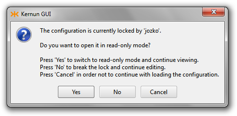

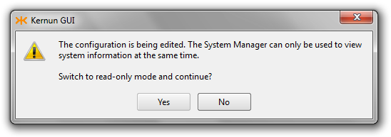
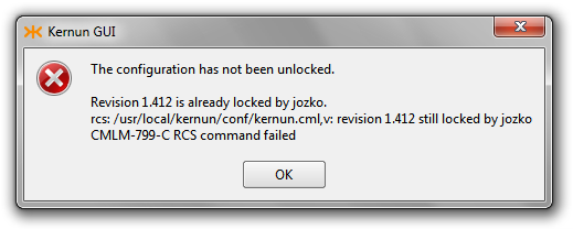
After the locking phase, the CML configuration editor checks whether the actual contents of the configuration file have been stored in the revision control system (RCS). If not, the user will be asked whether to do so (Figure 3.23, “Commit configuration to RCS confirmation”). The configuration file or the RCS version file may not even be initialized (Figure 3.24, “Initialize RCS confirmation”).
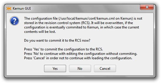
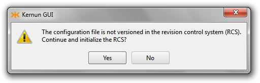
Before commiting the configuration to Kernun, the CML configuration editor checks whether it still owns the lock. If not, it may have either been broken and still locked (Figure 3.25, “Configuration lock broken”) or broken and then unlocked (Figure 3.26, “Configuration not longer locked”).
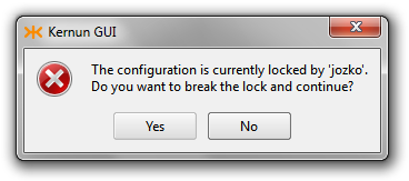
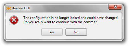
Besides the GUI (Section 1, “Graphical User Interface”) there is another approach to Kernun UTM services, namely the text-only, or command-line interface (CLI). Its common features as well as its particular tools are described further in this section.
All command-line tools can be used in the interactive mode, which means that they display prompts and expect commands entered by the user. The user can use common features of the command-line interface, known e.g. from the bash(1) tool, namely:
- History browsing
The user can browse through the list of commands entered recently using the cursor keys, change the command text and re-enter it by pressing the <Enter> key.
- History searching
Using the <Ctrl+R> key combination, the user can invoke the command history searching. When s/he starts typing a part of a command, the CLI displays the most recent command containing this string. When a cursor key is pressed, the search is stopped and the selected command is copied to the command line for further processing.
- Hotkey binding
Most of hotkey bindings known from bash(1) are available in Kernun UTM's CLI tools. For example, <Ctrl+A> skips to the beginning of the line, <Ctrl+E> skips to the end of the line, <Ctrl+U> clears the line, <Ctrl+D> exits the tool etc.
KAT@fw>apply fwCMLK-720-E Directory '/usr/local/kernun/conf' contains no SYSTEMKAT@fw>cml -gRCS file: /usr/local/kernun/conf/kernun.cml,v ... CKGB-719-N ---- System 'fw' successfully generatedKAT@fw><^R>Searching for: 'ap' > apply fw
Warning
The command history is saved when a CLI tool is closed
and made available again the next time it is started.
However, there is a bug in the library used for the line-editing
support and in some cases, the reading of the history file fails
and the tool coredumps.
The recovery is very simple: remove the history file
(~/.kat_hist for the KAT and
~/.cml_hist for the CML)
and restart the tool.
One of the most important and most useful features implemented in Kernun UTM's CLI tools is Command Completion and Context Help, or shortly C3H.
The C3H support helps you write correct commands or proper parameters more quickly. The rule of thumb is: “If you don't know what to do now, press the <Tab> key!”. Of course, it does not work absolutely perfectly in all situations, but it works e.g. when selecting a command name, a command argument name (if there is only a defined set of ones), a system name (the apply command in the KAT), a proxy name (application or process management in the KAT, language reference in the CML), a file name (some KAT or CML commands, a file name reference in the CML), a correct operator or delimiter (in the CML language), and many others.
KAT@fw><Tab>apply # apply generated system config files cml # start configuration tool ...KAT@fw>a<Tab>KAT@fw>applyKAT@fw>apply<Tab>KAT@fw>apply fw CMLK-820-N [root] Applying 'SYSTEM-fw', Source: kernun.cml,v 1.1 ... ... System /usr/local/kernun/conf/SYSTEM-fw applied to /.KAT@fw>start s<Tab>SMTP SSH SSHDKAT@fw>start Sm<Tab>KAT@fw>start SMTP CMLK-841-N [root] Executing 'start' operation of N=SMTP A= T= ... CMLK-849-N [root] Successful end of 'start' operationKAT@fw>ps -<Tab>-a -b -d -p -S -t -TKAT@fw>ps -p <Tab>KAT@fw>ps -p smtp-proxy
The KAT utility is the core management facility for administration of Kernun UTM. It is available directly on Kernun UTM when used locally, can be used when accessing Kernun UTM remotely in the text mode via SSH, and, in fact, most of operations implemented in the GUI (Section 1, “Graphical User Interface”) are realized using the KAT on the remote machine.
The complete command summary is available in kat(8); this section points out only the most important features and shows the typical tasks an administrator can do using the KAT tool.
The KAT can be used in two modes:
- Interactive mode
In this mode, the program is called without parameters. It displays its own prompt
KAT@and expects commands issued by the user. In this mode, the KAT accepts also ordinary UNIX shell commands, so it can be used as a simplified UNIX shell with added commands for Kernun UTM management.hostname>- Batch mode
In this mode, the program is called with a KAT command as a parameter; the command is executed and the tool exits. This mode is used for quick execution of a single KAT command without the need of starting the KAT explicitly.
[root@fw ~]#kat ps12345 1 Ss 0:00.01 SMTP: parent: ready on 1 address: ...[root@fw ~]#
The management of the Kernun UTM configuration is one of the most important functions provided by the KAT. The configuration tool CML (see Section 2.4, “CML — Configuration Meta Language” below) can be invoked from the KAT simply by typing the command cml. After finishing the configuration, the KAT apply command must be executed to put the changes into effect.
KAT@fw>cmlCMLI-700-N CLI interactive mode entered RCS file: /usr/local/kernun/conf/kernun.cml,v ... CMLR-710-K File '/usr/local/kernun/conf/kernun.cml' loadedCML>... work interactively with the CMLCML>./generate CKGB-719-N ---- System 'fw' successfully generatedCML>./quit CMLI-709-N CLI interactive mode closedKAT@fw>apply fwCMLK-820-N [root] Applying 'SYSTEM-fw', Source: kernun.cml,v 1.1 ...
In the case of a mistake, the administrator can
go through the log of previous revisions,
compare different versions and revoke an older one.
For this purpose, several commands have the -r option
with a value of revision number, or 0,
-1, etc. for previous RCS versions
of the configuration file.
KAT@fw>rlogRCS file: kernun.cml,v Working file: kernun.cml head: 1.2 ... ---------------------------- revision 1.1 date: ... Initial revision ---------------------------- ===================================================================KAT@fw>rcsdiff -r 0 -r 1.1=================================================================== RCS file: kernun.cml,v retrieving revision 1.2 retrieving revision 1.1 diff -c -r1.2 -r1.1 ...KAT@fw>cml -r -1CMLK-825-N [root] Revoking revision 1.1 of '/.../kernun.cml' CMLI-700-N CLI interactive mode entered
Kernun UTM consist of a set of components, and the KAT tool facilitates the work with them. The commands of this group work with the configuration currently applied in the system. Thus, applications that are not configured cannot be operated (e.g. stopped) using these commands. For such tasks, the process management (see Section 2.3.4, “Process management” below) commands need to be used. The commands have several options used to select the proper set of components by type, by name etc., and also by the current state of the component's configuration (e.g. restart only the updated ones).
KAT@fw>restart----> Are you sure to do this operation with the whole firewall? (y/[n])nKAT@fw>showapp -nSMTP smtp-proxy proxy - : UPDATED 50 CMLK-840-I Found 1 component(s)KAT@fw>restart -n SMTPCMLK-841-N [root] Executing 'restart' operation of N=SMTP A= T= ... CMLK-849-N [root] Successful end of 'restart' operationKAT@fw>showapp... SMTP smtp-proxy proxy - : CURRENT 50 ... CMLK-840-I Found 14 component(s)KAT@fw>restart -n SMTPCMLK-841-N [root] Executing 'restart' operation of N=ROUTES A= T= CMLK-740-W Component 'ROUTES' running, skipping... CMLK-712-E No appropriate component foundKAT@fw>
The running applications (components) of Kernun UTM can be operated using the commands of this group. The administrator can monitor a list of application processes and send them signals.
KAT@fw>ps -b SMTP12345 1 SMTP: parent: ready on 1 address: [192.168.10.1]:25KAT@fw>kill -info SMTP *12345 1 SMTP: parent: ready on 1 address: [192.168.10.1]:25 CMLK-830-N [root] Sending signal 29 to application 'SMTP'(), process: * CMLK-130-N [root] Sending signal 29 to process 12345KAT@fw>
The CML tool is a simple syntax-driven editor of the Kernun UTM configuration. The complete command summary is available in cml(8); this section points out only the most important features and shows the typical configuration tasks.
The user can move within the configuration in the manner very similar to moving across the file system, with the sections of the configuration playing the role of directories. At every moment, the user is in a node of the configuration tree; the “path” to the node is shown in the prompt. To descend into a subnode, simply type the subnode's header with the opening left brace. To ascend, analogously type the closing right brace.
CML>sy<Tab>CML>system<Tab><new name> fwCML>system fw {CML.fw>routes {CML.fw.routes>}CML.fw>
In the case of a command error or incompleteness, the CML advises the proper continuation in the prompt text.
CML.fw>routesCML.fw.routes> [OPEN]<Tab>CML.fw.routes> [OPEN]{CML.fw.routes>
Type an existing section to enter it for editing;
type a new one to append it after the “cursor”.
If a new node should be placed elsewhere,
the cursor position needs to be changed.
Special CML commands are used for such “control” operations.
To be distinguishable from the section and item names,
they start with a special character sequence
(“/”
or “./”).
The show command is used to display the content of
a node, the goto command to move the cursor.
CML.fw>./show[ 1] ## Host name without domain [ 2] hostname fw; ... --> [25] routes { ... } ... }CML.fw>./goto = acl--> acl INTOK { ... }CML.fw>acl NEW {CML.fw.NEW>} ... CMLR-592-W .: Section 'NEW' definition not correctCML.fw>./show . aclacl INTOK { ... } --> acl NEW { ... }CML.fw>
The above example illustrates also the “online verification” function. After completing the configuration directive, the CML tries to check whether it would be readable by the low-level configuration reader, and prospective errors are displayed.
The show and goto commands can be typed in a shortened version without names, as shown in the following example.
The rules for entering sections apply to items, too. Type a non-existent item to add it, or an existing unrepeatable item to change it. The only difference concerns work with repeatable items. If you type one, a new item will be added; to edit an item, use the edit command. The C3H (Section 2.2, “C3H — Command Completion and Context Help”) may help significantly, if used.
CML.fw>acl INTOK {CML.fw.INTOK>./acl INTOK { [ 1] from { ^system.INT.ipv4.net }; [ 2] service { DNS, FTP, HTTP, HTTPS, POP3, IMAP4, SMTP, SSH }; --> [ 3] accept; }CML.fw>1--> from { ^system.INT.ipv4.net };CML.fw.INTOK>./edit <Tab>CML.fw.INTOK>./edit from { ^system.INT.ipv4.net };CML.fw.INTOK>./edit from {$INT-ADDR};CML.fw.INTOK>from { $EXT-ADDR };CML.fw.INTOK>./acl INTOK { [ 1] from { $INT-ADDR }; --> [ 2] from { $EXT-ADDR }; [ 3] service { DNS, FTP, HTTP, HTTPS, POP3, IMAP4, SMTP, SSH }; [ 4] accept; }
Context-oriented online help is available at every point of the configuration using either C3H (the <Tab> key), or the info command.
CML.fw.INTOK>./info descrRepeatable section acl... General ACL definition. Constraints: Exactly one of DENY and ACCEPT must be specified. ... Item SERVICE must be specified.. acl <name> { * from ...; * to ...; ... service ...; }CML.fw.INTOK>doctype-ident-order <Tab>doctype-ident-order [for <for>] <order>; Elements: --> [ KEY DIRECTION-SET for = * ] DOCTYPE-IDENT-METHOD-LIST order
The delete command can be used to remove unneeded configuration directives (the last removed node can be restored using the undelete command). The hide command provides a similar function. However, a hidden node remains in the configuration, even though it plays no role in the actual configuration, and can be re-enabled in the future using the unhide command.
CML.fw.INTOK>./acl INTOK { [ 1] from { $INT-ADDR }; --> [ 2] from { $EXT-ADDR }; [ 3] service { DNS, FTP, HTTP, HTTPS, POP3, IMAP4, SMTP, SSH }; [ 4] accept; }CML.fw.INTOK>./delete--> service { DNS, FTP, HTTP, HTTPS, POP3, IMAP4, SMTP, SSH };CML.fw.INTOK>./undelete--> from { $EXT-ADDR };CML.fw.INTOK>./hide--> hidden from { $EXT-ADDR };CML.fw.INTOK>./unhide--> from { $EXT-ADDR };
The CML has a clipboard, which can be used to copy and move configuration directives. Repeatable sections can be renamed when being pasted.
CML.fw>./copyCMLM-751-N 1 node(s) stored to clipboardCML.fw>./pasteCMLT-570-E Section 'INTOK' already definedCML.fw>./paste NEW--> acl NEW { ... }
When the configuration changes are finished, the configuration should be saved. Before actually saving it, the CML verifies the configuration. If the verification fails, the save operation does not proceed. The verification can be skipped (e.g. when saving temporarily), but it is strongly recommended not to do so regularly.
CML.fw>./saveCKGB-711-N ---- Trying verification of system 'fw'... CFGR-500-E FTP.NEW: Authentication method must be set CFGR-500-E HTTP.NEW: Authentication method must be set CKGB-718-E ---- System 'fw' verification failed CMLM-713-E Saving cancelledCML.fw>./save !CMLS-715-N Configuration saved to file '/.../kernun.cml' /.../kernun.cml,v <-- /.../kernun.cml new revision: 1.3; previous revision: 1.2 enter log message, terminated with single '.' or end of file: >>temporary saving>>.done CMLT-800-N Configuration identification: kernun.cml,v 1.3 ...
Kernun UTM contains many administrative utilities, which can be invoked from the shell command line. The most important of them, kat(8) and cml(8), have been described in Section 2, “Command Line Interface”. In addition to these two utilities and the standard FreeBSD commands there is a set of Kernun-specific utilities, which are introduced in this section. For detailed description, see the respective reference pages.
Note
The full contents of terminal sessions of the administrator are
logged[16] in the
/var/log/session-USER-DATE-HOST.log.gz files.
- bootmgr(8)
Kernun UTM boot manager configuration tool. It can be used to view and set system partition labels, toggle the bootable flag of system partitions, and select the default system partition for the next boot. Its functionality is provided also by the GUI, on the Kernun systems page of the System Manager.
- diskdb(1)
This program can traverse the file system and create a database file containing information about all files and directories in it. It is able to compare two such databases and display the list of changes to the file system between the times of creation of the databases. The diskdb program is used internally by the Kernun UTM backup, restore, and upgrade tools. It can be used also to detect unexpected changes to vital system files.
- fwpasswd(1)
Program for management of password files for user authentication. See Section 14.1, “Authentication Methods” for more information.
- log-ts(1)
It selects messages from Kernun UTM's logs using various criteria. Automatically selects the log files that cover the required time interval.
- kernun-audit(1)
This tool reports bugs in the installed Kernun software and availability of new versions. It is usually run automatically at a regular interval (daily) and the reports are e-mailed to the administrator. See also Section 8, “Audit”.
- mkblacklist(1), printblacklist(1), resolveblacklist(1)
Utilities for manipulation and viewing of blacklists for http-proxy(8). See Section 18.2, “Blacklists in HTTP Proxy” for instructions on the use of blacklists in the HTTP proxy.
- monitor(1)
A utility for online monitoring of active proxy sessions. Monitoring is provided also by the GUI on the GKAT Monitor pages for proxies. The configuration of monitoring is described in Section 6.3, “Monitoring of Active Sessions”.
- ooba-samba(1)
This script is used by the out-of-band authentication to obtain the list of logged-in users from a Samba server. The script should be copied to the Samba server machine and run automatically, as described in Section 14.8, “Out of Band Authentication”.
- quarc.sh(1)
A tool for SMTP proxy quarantine management. In the ACLs of the smtp-proxy(8) it can be specified that some mail messages are not to be delivered, but stored in the quarantine instead. The quarantine management tool can be used to list the quarantined content, as well as remove or resend messages from the quarantine.
- rrd(1)
This is the command line interface to system parameter monitoring, as described in Section 6.5, “Monitoring of System Parameters”. It is also used by the GUI to generate graphs displayed on the Graphs page (Figure 3.8, “Graphs page”).
- sum-stats(1)
This script processes Kernun UTM logs and generates proxy statistics. The configuration of statistics is described in Section 6.4, “Proxy Statistics Generation”. The statistics can be displayed by the GUI in the window invoked by selecting from the main menu.
- switchlog(1)
This is a program for fast filtration of a Kernun UTM log based on proxy name and message ID matching. It can multiplex selected messages to several output streams for further processing. For example, the process of proxy statistics generation uses switchlog to quickly select statistical messages written by proxies and pass them to sum-* scripts.
- triplicator(1)
A tool for SMTP proxy greylisting database management. Greylisting is one of antispam techniques implemented in Kernun UTM. See Section 16.2, “White-, Grey-, and Blacklists” for more information.
- sysmgr(8)
This is the command-line alternative to the GUI System Manager window. It can perform installation, upgrade, backup, and restoring of Kernun UTM. Refer to Chapter 2, Kernun UTM System Management for detailed instructions on how to perform various Kernun system management tasks.
[12] The binary executables are compiled for the version of FreeBSD used by Kernun UTM.
[13] Usually, there are many simultaneous requests on each Kernun UTM proxy, which need to be handled simultaneously. To do that, for every proxy there is one parent process, which only manages its child processes (starts and kills them), while these child processes take care of the traffic. Therefore, the number of the child processes depends on the current traffic.
[14] Kernun UTM uses the PF packet filter (see
pfctl(8) and
pf.conf(5)), which provides
stateless and stateful packet filtration, NAT, and traffic
shaping.
[15] A session encompasses the communication of a particular proxy process with a single client.
[16] A session is copied into a file using the
screen
(1) command invoked from
/root/.profile.
In the first section of this chapter, we will introduce the principles of
the Kernun UTM configuration. We will describe the syntax and semantics of the
configuration language and its two different representations. The textual
representation is used in the configuration file (usually
/usr/local/kernun/conf/kernun.cml) and by the command
line configuration tool
cml(8). The graphical representation is used
by the Kernun GUI. Then we will discuss the initial
configuration that is generated when the newly installed Kernun UTM is booted for
the first time. We will explain the meaning of individual items in this
configuration and how to change them. For information about configuration of
additional functionality not included in the initial configuration, such
as more types of proxies, authentication, antivirus, or antispam
modules, refer to Chapter 5, Advanced features.
Kernun UTM keeps its configuration in a text format called CML
(Configuration Meta Language). The configuration is usually stored in the
/usr/local/kernun/conf/kernun.cml file. Whenever the
configuration file is saved by the GUI or command line tools, it is also saved
to a RCS (Revision Control System) file called
/usr/local/kernun/conf/kernun.cml,v. The RCS file contains
the complete history of the configuration, which makes it possible to return to
any past version of the configuration file, show differences between two versions,
and more. The Kernun GUI and
cml(8) provide functions for work with RCS
files. For more advanced operations with RCS, you can use command line system
tools, see rcsintro(7).
Speaking more precisely, there are two levels of configuration: high and low. Usually, the administrator maintains only the high-level configuration file. On the other hand, each Kernun UTM component reads its low-level configuration file upon starting. The Kernun UTM configuration handling tools generate a set of low-level configuration files[17] from the single high-level configuration file. In fact, the high-level configuration is more or less an extension of the low-level configuration of proxies. This concept makes it possible to keep a simple configuration file for each proxy and, at the same time, maintain a single file that describes the whole system in a comfortable way.
The configuration has a tree structure consisting of sections, items, and elements. A section is a named group of logically connected configuration directives. It can contain other (sub)sections and items. An item is a named group of values—elements. The configuration structure is reflected by the view of the configuration in the GUI, see Figure 4.1, “Tree structure of the configuration”, as well as in the corresponding textual configuration file:
## Configuration of a single Kernun UTM system
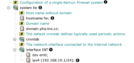
In the sample configuration there is a section of type system
named fw . It contains several
subsections and items. For example, an item hostname with
an element (value) fw , or
a subsection interface named INT containing
an item ipv4 . Note that it is
possible to include comments in the configuration file. They are also
displayed by the GUI .
Nodes of the configuration tree are referenced by
paths. A path lists the ancestor sections in the tree. In
the above example, the fw.INT.ipv4 path denotes the item . Instead of specifying a value for an element, it is
possible to use a reference to another value in the configuration with the
same type. For example, the initial configuration contains
Here, denotes the value obtained by going up
the tree to the system type node (section
system fw), and then down to the node named
INT (it is interface INT), then to
ipv4, and finally we take its host element
(value).
References ensure the consistency if the same value appears at two or
more places in the configuration. If the same path is to be repeated
several times, e.g., in listen-on of several proxies, we
may avoid the use of the full path by using a
variable.
system fw {
interface INT {
dev em0;
ipv4 [192.168.10.1/24];
}
set INT_IP = ^system.INT.ipv4.host;
...
## SSH daemon for remote administrator access from the internal network
ssh-server SSHD {
listen-sock $INT_IP : 22;
passwd-auth;
}
The previous example is changed so that the reference path is stored in a
variable called INT_IP and the
variable is used instead the full path later .
For the GUI view of the same configuration, see Figure 4.2, “Tree structure of the configuration”.
In addition to these data variables it is possible to
define variables containing several configuration items or even whole
sections. These section variables can be parametrized.
A simple example of section variables will be shown in the next paragraph,
along with file includes.
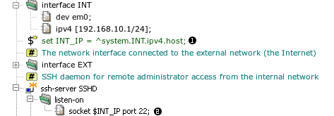
A configuration file can include another file. After
the installation there are several include files in
/usr/local/kernun/conf/samples/include. The initial
configuration includes two of them, root-servers.cml (a
list of root DNS servers) and crontab.cml (the default
configuration of the
cron
(8) daemon that runs
periodic actions in the system, e.g., log rotation). Example: the
crontab.cml include file contains
set DEFAULT-CRONTAB system.crontab {
...
}
set DEFAULT-PERIODIC system.periodic-conf {
set-env daily_clean_hoststat_enable "NO";
set-env daily_status_disks_df_flags " -i";
set-env daily_status_mail_rejects_enable "NO";
set-env daily_status_include_submit_mailq "NO";
set-env daily_submit_queuerun "NO";
}
It is included in the main configuration file kernun.cml
include "samples/include/crontab.cml";
...
system fw {
...
crontab {
$DEFAULT-CRONTAB;
}
The same excerpt of the configuration viewed in the GUI is shown in Figure 4.3, “Including configuration files and using section variables”.
The crontab.cml file is included at
DEFAULT-CRONTAB and
DEFAULT-PERIODIC. The first variable is used
at
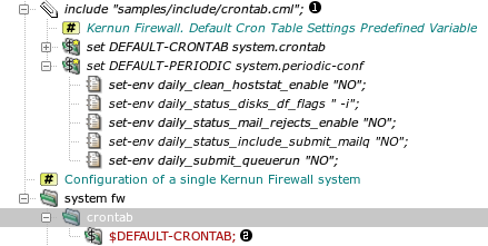
Configuration elements are of various types. All the types and their exact syntax are described in configuration(7). Here we only list the types and present the most important syntax rules.
Integers — a nonnegative decimal or hexadecimal value; several types with different numbers of bits
Port number — an integer or a service name from
/etc/servicesString — a sequence of characters in double quotes. It is possible to omit the quotes for strings that contain only a limited set of characters.
Regular expression — delimited by slashes
Host — an IP address in dotted decimal format enclosed in brackets or a host name
Interface address, network address — an IP address with mask, enclosed in brackets
Socket — a host and a port number
Enumeration — a set of names representing integer constants
List — a sequence of values of a basic type, separated by commas and enclosed in braces. Lists can be nested.
Set — a set of values of a basic type. Syntax is similar to lists with additional features—ranges, exclusion of members, and wildcards. Sets of some types allow special members, e.g., regular expressions in a set of strings or host addresses.
Important
In the GUI, the values must be entered including quoting characters, such as double quotes for strings and brackets for IP addresses.
We have introduced only the basic concepts of the Kernun UTM configuration
language. The complete definition of the language syntax can be found in
reference pages
configuration(7) and
cml(8). The semantics of the configuration is
defined by the meaning of individual sections, items, and elements. Semantic rules
also define the subsections and items each section may contain.
There are constraints, e.g. that the existence of a configuration node
requires or forbids the existence of another node. The set of possible values of
a configuration element can be limited. A section or item can be repeatable
(can occur several times, in the case of sections with different
names), or non-repeatable (cannot occur more than once;
non-repeatable sections do not have names). For example, in Figure 4.1, “Tree structure of the configuration”, the named sections system and
interface are repeatable, whereas the section
crontab is non-repeatable. The semantics of the configuration is
described comprehensively in section 5 of the reference pages (in the appendix of
this handbook or in manual pages displayed using the
man(1)) command.
A newly installed Kernun UTM is configured by an interactive script during
the first boot, as described in Section 5.2, “Initial Configuration”. The initial
configuration is identical to the configuration sample file
/usr/local/kernun/conf/samples/cml/simple.cml. The
configuration script takes this file and substitutes the values of parameters
entered by the administrator, e.g., IP addresses. The configuration file
simple.cml is suitable for Kernun UTM with two network
interfaces, one connected to the internal (protected) network and
the other to the external network (the Internet). Kernun UTM
will be configured so that clients that use selected network protocols in
the internal network may access servers in the external network, but access is
denied for other protocols and to clients in the external network. The administrator
can connect to Kernun UTM from the internal network. Although it is possible to
enable proxies for some application protocols using the initial configuration
script, we will assume that the administrator has chosen the more secure way,
i.e., not to enable any proxy initially, but to do so later selectively
using the GUI.
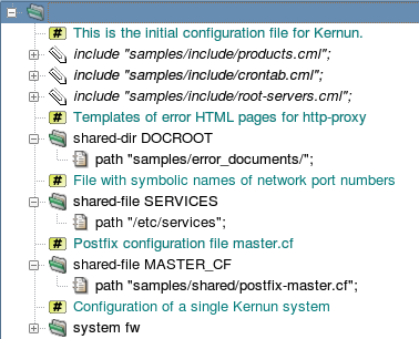
The global level of the initial configuration file is depicted in Figure 4.4, “The global level of the initial configuration file”. It begins with three standard include
files[18].
The first file, samples/include/products.cml, defines
variables usable as the system.product item. See Section 3, “Licensing” for more information about Kernun product
specification in the configuration.
The second file, samples/include/crontab.cml, defines
variables usable as the contents of the system.crontab and
system.periodic-conf sections. The third file,
samples/include/root-servers.cml, contains a list of
root DNS servers. Then, several
shared-dir and shared-file sections
specify files that are copied from the configuration directory to their
target locations when the configuration is applied. The configuration
can be edited on one Kernun UTM and then applied remotely to another. In this
case, the shared files and directories are copied from the system where the
configuration is edited to the system where it is applied.
The rest of the sample configuration is the system fw
section. It defines a single Kernun UTM system. The configuration of a standalone
Kernun UTM usually contains only one system section. If several
alternative configurations are used or several systems are configured from
one place (e.g., in high-availability clusters), more than one
system sections can be defined.
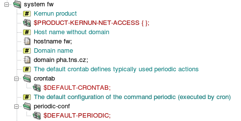
First, the type of the Kernun product is specified (Figure 4.5, “Various system-level definitions”) using one of standard product variables
from samples/include/products.cml. The
product specification controls which components can be configured. During
the application of the configuration, a check is made that the product
installed on the target system matches the specification. See also Section 3, “Licensing” for a more detailed explanation of the product
specification in the configuration. The
system parameters start with host and domain names.
The configuration of actions executed periodically by the
cron
(8) daemon and by the
periodic
(8) command is
defined in the sections crontab and
periodic-conf. These sections are filled in by
the application of variables defined in crontab.cml.
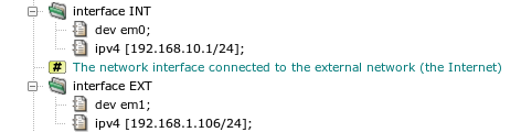
The following part of the system section, displayed
in Figure 4.6, “Definitions of network interfaces”, contains the
settings of two network interfaces, connected to the internal
(INT) and external (EXT) network, respectively.
Two values are specified for each interface: the name of the network interface
device as used by the operating system (item dev), and
the IP address with the network mask (item ipv4). Note that
interface is a repeatable section, so it can occur more
than twice. For example, a demilitarized zone network can be connected
via a third interface in a more complex network topology.
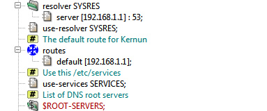
The system section then defines further network-related
parameters, see Figure 4.7, “Definitions of various network parameters”. Domain name
resolution parameters are set in the section resolver. In
the initial configuration, the only item in this section selects a DNS
server. There may be several resolver sections. The
section that is used globally for resolutions performed by Kernun UTM components
is chosen by use-resolver. Each proxy can use the global
resolver, or the resolver setting can be overridden for the proxy using a
use-resolver section local to the proxy configuration
section. In the initial configuration, the global resolver is shared by
all proxies. Note that the resolver is used for address resolution performed
by Kernun UTM itself. If clients in the internal network should have access
to the DNS, which is usually the case, either a DNS server can be configured
in the internal network, or the clients can resolve via
a Kernun UTM dns-proxy.
Note
As the Kernun UTM dns-proxy does not cache responses
obtained from DNS servers in the external network, it is inefficient
to configure clients in the internal network to resolve directly via the
proxy. The recommended configuration is to create a caching-only DNS
server in the internal network and to set dns-proxy
as its forwarder. The internal DNS server can be created in Kernun UTM,
by adding section system.nameserver to the configuration.
The routes subsection defines static routes. In the
sample configuration, only the default route to a router
in the external network is specified. The use-services item
selects a shared-file[19] that will be copied into
/etc/services. It defines port numbers assigned to
various network services. The last network-related parameter is a list of
root DNS servers, section ns-list. It is set by the
application of the section variable ROOT-SERVERS defined
in the included file root-servers.cml.
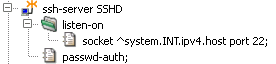
Kernun UTM is usually administered remotely via the network. The
administrator connects to Kernun UTM using SSH, either directly in order to
obtain a shell command line, or via the GUI, which uses SSH internally.
Therefore, an SSH server for administrator's access should be defined in the
configuration. The initial configuration contains a single SSH server
section called ssh-server SSHD, see Figure 4.8, “An SSH server for administrative access”. It listens on the standard
SSH port 22 on the internal network interface only. Hence the administrator
can connect to the Kernun UTM from the internal network only. If access from the
external network is desired, the SSH server must be reconfigured to listen
on the external interface as well.
The server allows password-based authentication of non-root users. It
is used for the initial download of the root's SSH key using the special
keygen account, as described in
Section 5.2, “Initial Configuration”. The root can log in to Kernun UTM with the SSH
keys listed in section ssh-keys. By default, this section
contains the key generated by the initial configuration process and
accessible via the keygen
account.
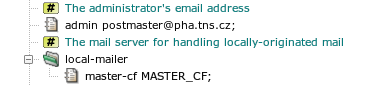
Kernun UTM generates some e-mail messages locally, mainly as the
output of periodic actions executed by
cron
(8). These messages
are delivered to the address provided in the admin item by
the mail server configured in the local-mailer section, see
Figure 4.9, “The server for handling locally-originated mail”. The default local mailer
configuration refers to the standard file master.cf
selected by a global shared-file parameter.
The server that handles local mail is Postfix-configured so that it
does not listen for any incoming network connections. It handles only mail
sent by the mail
(1) command. The
administrator's e-mail address is set as an alias for the root user in
/etc/aliases.
Kernun UTM utilizes both the packet filter and application proxy firewalling technologies. The use of application proxies is preferred, because it provides a higher level of security and finer control of the network traffic. The network traffic is therefore passed through Kernun UTM mainly via proxies that handle individual application protocols.
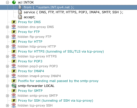
It is possible to enable proxies for several frequently used network protocols in the initial configuration. However, in order to maintain better control over the network traffic it is advisable not to enable any proxy when the initial configuration script creates the configuration of a newly installed Kernun UTM, but rather to selectively enable and configure the proxies later, when the administrator connects to Kernun UTM via the GUI. The part of the configuration that is directly related to proxies is shown in Figure 4.10, “Hidden proxies and a global ACL”. Note that all proxy sections are hidden, so that proxy parameters are defined, but have no effect and the hidden proxies are not started[20].
Proxies can be non-transparent or transparent, see
Section 7, “Networking in Proxies” for more details. By
default, all proxies in the initial configuration except
dns-proxy are configured as transparent, which enables
the use of clients in the internal network without any reconfiguration.
Access control in proxies is driven by access control lists (ACLs). Each proxy has one or more layers (phases) of ACLs. Individual phases are consulted at specific moments during the processing of the network communication.
For example, in http-proxy,
there are three phases of ACLs: the session-acl sections
are consulted when a new connection from a client is accepted. They make
early decisions based on values, such as the client's IP address. The second
phase, request-acl, is checked after the HTTP request is
received from the client. Its actions can depend e.g. on the request URI
or on the values of some request headers. The third phase,
doc-acl, is applied when the HTTP reply headers are received.
On the other hand, tcp-proxy, which handles only the TCP
data stream without deeper understanding, has a single ACL phase,
session-acl.
The ACLs that belong to one phase are tested sequentially. The input
conditions of every ACL section are evaluated and the first ACL, for which all
the conditions are true, is selected. The chosen ACL can accept
or deny the session, thus effectively allowing it to continue
or terminating it. Various parameters that affect further
handling of the session by the proxy can be set by the ACL. If no matching
ACL is found, the session is terminated.
ACLs can be located at two different places in the configuration.
Global ACLs defined in the system section belong to the
first phase (session-acl). Each global ACL has a
service item containing the list of proxies, to which
it is applicable. The initial configuration contains one global
acl INTOK that applies to all proxies and accepts
sessions originated from clients in the internal network, as can be seen
in Figure 4.10, “Hidden proxies and a global ACL”. Note that sessions initiated by
clients in the external network do not match the from
condition of acl INTOK and there is
no other ACL that could match, hence these sessions are
denied[21]. Local ACLs are defined in the configuration
sections of individual proxies. Each such ACL applies only to the proxy,
in which it is defined. Phase one (session-acl) ACLs in
a proxy are merged with the global ACLs that have this proxy in their
service lists. For each session-acl in
a proxy there must be a global ACL with the same name.
Note
The first-phase ACLs are checked in the order defined for the
global ACLs. The per-proxy session-acl sections can
add proxy-specific items to the ACLs, but do not change the order of ACLs.
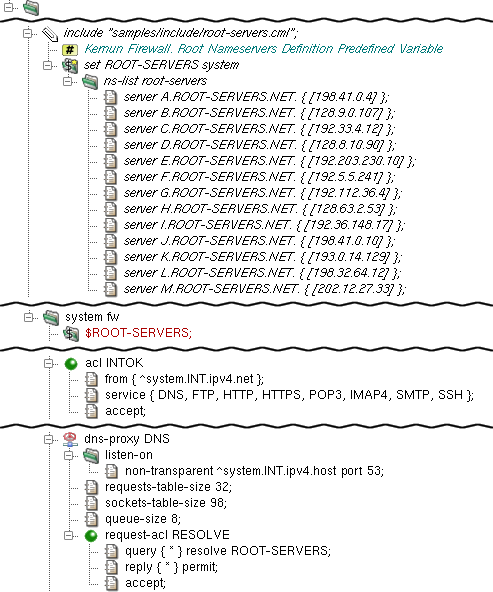
In a typical scenario, the DNS proxy provides the domain name
resolution service for clients behind Kernun UTM. It is defined by its
particular dns-proxy section which resides in the
system section. In this example, the
listen-on section specifies that the DNS proxy will listen
non-transparently on the internal interface on port 53. This means that
clients from the internal network must set the IP address of Kernun UTM's
internal interface as their DNS server in order to use this proxy. The
chroot-dir item specifies that the process will be
chrooted to the directory
/usr/local/kernun/root, see chroot(8).
The requests-table-size and
sockets-table-size items are obligatory for
dns-proxy. Every domain name resolution request is stored
in a table that contains all the necessary information. The size of this
table is specified by the requests-table-size item. It is
recommended to reserve slightly more items than the estimated number of
parallel requests. Besides the number of requests, the number of simultaneously
opened sockets is monitored as well. This maximum must be specified by the
sockets-table-size item. See dns-proxy(5) for details.
Caution
The DNS proxy is not designed to be used as a name server. The typical scenario is that all clients ask another server in the internal network and this server queries the proxy (if needed) and caches the answers. See Section 3, “Caching Name Server” for details.
dns-proxy needs at least one
request-acl section providing details on what
traffic is permitted or not, and the way it should be dealt with. In
this example, the accept item specifies that
request-acl RESOLVE describes an
accepting request-acl. This means that this section defines
the positive case — the conditions, under which the request is accepted.
Then query * resolve ROOT-SERVERS directs the proxy to use the
ROOT-SERVERS to resolve all the requests. Further on, it is
defined that all the respective replies from the
ROOT-SERVERS are permitted to be returned to the clients.
The ROOT-SERVERS item is defined in the sample file
samples/include/root-servers.cml, which is included
in the configuration using the include keyword. This file contains
the definition of the $ROOT-SERVERS variable, which defines the
ns-list section — a list of DNS root servers.
In order to apply that definition, it is necessary to
include the $ROOT-SERVERS keyword in the configuration.
Finally, dns-proxy must be referenced by at least one
system ACL. In this example, the access to the DNS proxy is granted for all
clients from the internal network.
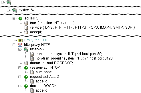
http-proxy is the proxy daemon for HyperText
Transfer Protocol (RFCs 1945, 2616). It supports version 0.9, 1.0 and 1.1
HTTP clients and version 1.0 and 1.1 HTTP servers. The proxy also supports
secure communication via the SSL/TLS protocols.
In the example depicted in Figure 4.12, “HTTP Proxy”,
http-proxy is configured to listen on the internal
network interface on port 80 in the transparent mode, and
on port 3128 in the non-transparent mode; see Section 2.5, “Application Proxies and ACLs” for details about transparency.
Again, the proxy is configured by chroot-dir to be chrooted
into /usr/local/kernun/root/, see chroot(8).
The document-root item defines the root directory
of the error document set. In this example, it refers to
DOCROOT — the shared-dir section
defined at system is a list of path
items designating directories for further use. Note that the relative path
(i.e., one that does not start with “/”) is in fact relative
to /usr/local/kernun/conf.
http-proxy uses three-phase ACLs.
session-aclis checked once for each client connection. It permits or denies client access and sets some connection parameters.request-aclis checked for each HTTP request after the request headers are received from the client, but before anything is sent to the server. It decides whether the request is permitted or denied, and it can also set some request parameters. Note that there can be several requests per connection if persistent connections are used.doc-aclis checked for each HTTP request after the response headers are received from the server, but before the response is sent to client.
Important
The session-acl section of any proxy is always based on
an acl defined at the system
level. The items that are common for all types of proxies are defined
in the common part at the system level. The items
that are specific for each proxy are defined within the particular
proxy's section
[22].
In this simple example, http-proxy is configured not to
use authentication (auth none). You might have noticed
that we did not specify the accept item in
session-acl INTOK, nor did we restrict
the IP range of clients that can use http-proxy.
The reason is that we only specify the acl
section INTOK that we defined earlier. In fact,
FIREWALL.HTTP.INTOK is a local copy of
FIREWALL.INTOK, and we have particularized this local copy.
Finally, request-acl and doc-acl are
configured to accept any request or document, respectively. However,
CONNECT method requests are limited to port 443 to allow SSL/TLS
connections only.
See dns-proxy(5) for details.
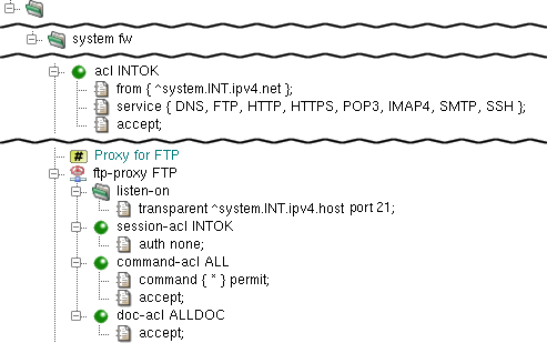
ftp-proxy provides the proxy service for
File Transfer Protocol (RFC 959) and its extensions. For crucial commands,
it behaves like a server for the client and vice versa, with full syntax
and semantics verification. Commands that have no impact on the session state
are only recognized and simply forwarded to server.
The simple configuration of ftp-proxy is quite
similar to the simple configuration of http-proxy
(see Section 2.7, “HTTP Proxy”). In the example at Figure 4.13, “FTP proxy”, it is configured to
listen on the internal network interface on port 21 in the
transparent mode and chrooted into
/usr/local/kernun/root/ (see
chroot(8)). No restrictions are configured,
so everyone (from the internal network — as specified
in the INTOK acl) is allowed to use the
ftp-proxy. As usual, the ftp-proxy FTP
must be present in some ACL; in this case, it is referenced
in the service list in the INTOK
definition.
ftp-proxy uses three-phase ACLs.
session-aclis checked once for each client connection. It permits or denies client access and sets some connection parameters.command-acldecides how to handle particular protocol commands depending on client parameters, destination server, proxy-user, etc. Each command is checked againstcommanditems in the order of their appearance in the cfg file, and the first matching one is used. If no one matches, the command is denied.doc-aclis checked for each HTTP request after the response headers are received from the server, but before the response is sent to the client. It decides how to handle particular files transferred via the proxy, depending on the file name, type and transfer direction.
For more information about ftp-proxy, see
ftp-proxy(8) and ftp-proxy(5).
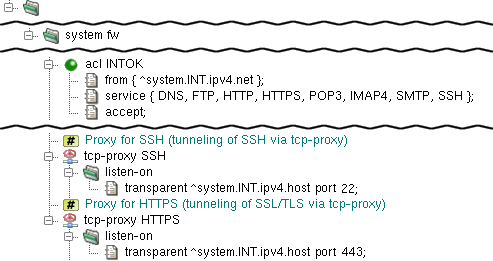
Both HTTPS and SSH protocols are handled by the generic
tcp-proxy, because they use encrypted communication and
Kernun UTM therefore cannot understand the protocol data. The configurations
of tcp-proxy HTTPS and
tcp-proxy SSH are almost identical, see Figure 4.14, “Proxies HTTPS and SSH”. They differ only by the port they
listen on—the port number is 443 for HTTPS and
22 for SSH.
Both proxies listen for clients connecting transparently via the
internal interface of Kernun UTM (section listen-on).
The proxies run with identity of proxy-user kernun
and are chrooted into directory
/usr/local/kernun/root. They do not define any ACL,
therefore the global acl INTOK applies to them
unmodified.
smtp-proxy is the proxy daemon for Simple
Mail Transfer Protocol (RFCs 2821, 2822, 2045 etc.). The SMTP protocol
is used to send electronic mail from clients to mail servers as well
as between mail servers. The task of
smtp-proxy is to apply a security policy, check the incoming
mail for correctness and then use some smtp-forwarder
to queue and distribute mail. In other words, there must be an SMTP
server (other than Kernun UTM) to deliver e-mail.
The easiest way is to employ the common UNIX postfix
daemon for this task. The configuration can be included in the
Kernun UTM configuration and the proper configuration
files for postfix are then generated automatically.
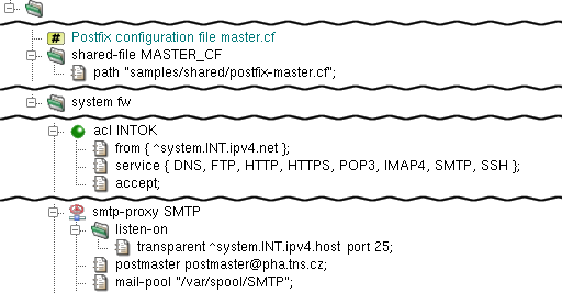
In the typical scenario depicted in Figure 4.15, “SMTP Proxy System Sections and Forward Agent”, postfix is
configured to listen at Kernun UTM's loopback address and forward
e-mails send to it by smtp-proxy, which listens
at Kernun UTM's internal address. Note that under this settings mail
does not arrive from the Internet to the internal network. We will
explain an alternative scenario in the second part of this chapter.
The postfix program is configured from
Kernun UTM by the agent
section in smtp-forwarder. It must contain a
master-cf item — an anchor to
shared-file that contains the Postfix
master.cf configuration file. There is a sample
in samples/shared/postfix-master.cf. There also
must be specified at least one server item in
smtp-forwarder — an address, to which the
mail is to be sent.
The proxy itself listens transparently on Kernun UTM
internal address port 25 (as defined by the listen-on
section). Besides the common chroot-dir item there must also be
present a postmaster item, which defines the postmaster e-mail address,
and a mail-pool item, which defines the directory used as temporary
storage for incoming mails.
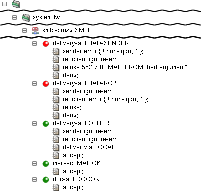
smtp-proxy uses four types of ACLs on three
levels:
session-acl— (level 1) is checked once for each client connection. It either defines the general protocol behavior, or rejects the connection. In addition to the generic ACL conditions and actions, some smtp-proxy-specific conditions and parameters can be set (see smtp-proxy(5)).
delivery-acl— (level 2) is checked once for each mail recipient. It either defines the response to the RCPT TO command, i.e. the way of delivery, or rejects the particular addressee.
mail-acl— (level 3M) is checked once for each mail recipient. Its rules control whether the forwarding of the mail to the particular recipient should be rejected or accepted.
doc-acl— (level 3D) is checked once for each recipient and document (MIME part) and defines the document processing mode (e.g. filtering, replacing etc.).
The example in Figure 4.16, “SMTP Proxy ACLs” shows three
different delivery-acl items. The first one
(BAD-SENDER) refuses mail with incorrect senders
(i.e., the MAIL FROM argument), the second one (BAD-RCPT)
rejects mail with incorrect recipients and the last one
(OTHER) accepts all other mail (that is, mail that
matches neither of the preceding delivery-acls). The
mail-acl and doc-acl items are configured
to accept all e-mails.
During the delivery-acl phase, the correctness of all the commands
(HELO, MAIL FROM and
RCPT TO) and their arguments is checked
and the proper decision is made.
Warning
When resolving domain names, the current
resolver section setting is applied.
It means that the search list (if present)
is tried when some resolution fails.
If this search-list contains a domain that has
the *.domain MX record set,
every resolution
succeeds and errors such as unknown-perm
never occur. This is probably not the desired behaviour.
You can solve this problem by defining a new
resolver section
without the search item
and then using this resolver
in the particular smtp-proxy only
by means of a use-resolver item
in the proxy's configuration section.
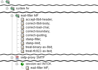
smtp-proxy checks the correctness of the mail
headers and MIME structure. Mail that does not conform to the RFCs is rejected.
However, many clients do not respect RFCs and if the security policy
allows sending of such e-mails, you can instruct the proxy to correct or even
pass them. We therefore add a mail-filter item, which handles
the most common cases, to the session-acl item. For details on
the particular entries, see
smtp-proxy(8) and
mod-mail-doc(5).
In the example depicted in Figure 4.17, “SMTP Proxy Mail Filter”,
a reference to mail-filter is added into
session-acl of smtp-proxy. The
mail-filter itself is configured to:
accept-8bit-header— accept non-US-ASCII characters in mail or MIME document headers;correct-8bit-body— accept and correct missing declaration of the use of non-US-ASCII characters in mail bodies or MIME documents;correct-bad-char— accept and correct the use of NUL char (0x00) or bare CR (not followed by LF) in mail bodies or MIME documents.correct-boundary— accept and correct the use of incorrect characters in MIME multipart boundaries.correct-quoting— accept and correct characters in SMTP and MIME headers that should be included in quotes, but are not.stamp-filter— remove 'Received:' headers that contain local-dependent information from mails. The number of the removed lines is counted and added to the e-mail as a special header X-Kernun-Loop-Info.stamp-limit 30— define the maximum number of Received-headers in mail. This check prevents mail loops.treat-binary-as-8bit— accept messages that use BINARY Content-Transfer-Encoding and treat them as 8BIT, even though it makes no sense in the current SMTP.treat-rfc822-as-text— handle the included documents as text.
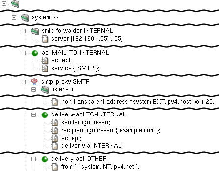
There can be a mail server in the internal network. This type of mail server usually serves as the SMTP forwarder for the internal network (that is, it forwards mail addressed outside the local network, and stores mail addressed to the internal network).
From Kernun UTM's point of view, the internal SMTP server
sends some e-mails[23]
to the internal interface of smtp-proxy.
Such mail is already handled by smtp-proxy configured
sooner in this chapter. What is new is that there can be mail from the
external network addressed to someone in the local network (precisely
speaking, to the mail server in the internal network). Kernun UTM should
therefore listen on the external interface, accept mail addressed
to the internal network and forward it to the internal mail server.
It is possible either to create another SMTP server, or to extend the
existing one. The example in Figure 4.18, “SMTP Proxy Mail Sever in the Internal
Network” shows the latter option:
Unlike other screenshots, the figure shows only the
sections and items added to the configuration of the sample
smtp-proxy. A new smtp forwarder INTERNAL,
which forwards mails to the internal network
(to the server 192.168.1.25), has been added. Then there is
smpt-proxy SMTP configured to listen in the non-transparent
mode on the external interface on port 25. Furthermore, there is new
delivery-acl TO-INTERNAL, which accepts only e-mails for
the selected domains (example.com) and delivers them via
smtp-forwarder INTERNAL. Note that the order of the
access control lists of the same type (delivery-acl in
this case) is significant. When Kernun UTM looks
for the delivery-acl to use, it follows the first matching
one and then stops the search. The delivery-acl TO-INTERNAL
section must be therefore created between the BAD-RCPT and
OTHER sections configured earlier. The delivery-acl
OTHER section has slightly changed; it now accepts only mail from the
internal network. Note that from { ^system.INT.ipv4.net
}; must be located at the beginning of the ACL, so that the entry
conditions are kept before the action (accept in this
case). Finally, the original delivery-acl OTHER was
restricted to accept mail from the external network (which was not
necessary until the second listen-on item was added).
The IMAP4 and POP3 protocols are used to access electronic mail that is stored on mail servers. Both make it possible for client e-mail programs to download mail and present it to the user. Unlike POP3, IMAP4 enables them also to upload mail to the mailbox on the IMAP4 server.
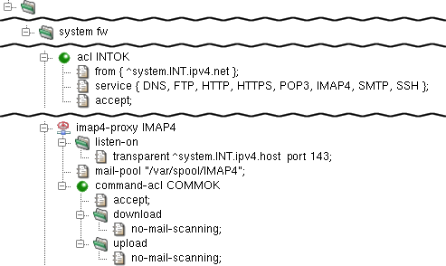
imap4-proxy is the proxy daemon for Internet
Message Access Protocol version 4rev1 (IMAP4rev1), as defined by
RFC 3501. The proxy supports secure communication via the SSL/TLS
protocols.
The proxy is configured in the imap4 section.
In the sample configuration depicted in Figure 4.19, “IMAP4 Proxy”,
the proxy-user and chroot-dir items
define the operating-system-level user, under which the proxy should run,
and the directory, to which it should be chrooted. The proxy listens
transparently for requests at Kernun UTM's internal address at port 143 and,
again, the proxy must be referenced by at least one ACL in the
system section.
The mail-pool item defines the directory,
in which e-mails are temporarily stored by the proxy. Note that this
directory must be created manually by the administrator and that it
must be writable by proxy-user. Note also that the
directory can be the shared by smtp-proxy,
imap4-proxy and pop3-proxy (or by
any combination of them).
imap4-proxy uses three-phase ACLs. The first
phase, session-acl, is checked once for each client
connection. It permits or denies client access and sets some connection
parameters. The second phase, command-acl, is also
checked once for each connection, but it can be selected according to
the client certificate if SSL/TLS is enabled by
session-acl. Various parameters can be set in
command-acl, e.g., the permitted sets of IMAP4 commands
and capabilities, timeouts, SSL/TLS on the server connection.
The third-phase ACLs are used only if mail processing is enabled in
command-acl. Two types of these ACLs exist.
mail-acl is checked once for each transferred e-mail.
It defines the rules of the acceptance or rejection of the mail according
to its content and antivirus/antispam test results. doc-acl
is checked once for each document (MIME part) of a mail. It defines
document processing, e.g., filtration or replacement by a fixed file.
See mod-mail-doc
(5).
In this example, command-acl COMMOK defines
that no mail scanning is to be performed on either downloaded or
uploaded e-mails. The item no-mail-scanning means,
in this context, that the mail is not even opened. Were the
no-mail-scanning item absent, the mail would be
stored and unfolded to headers and attachments, etc., and various tests
could be performed on any part. This alternative will be discussed in
Section 15, “Antivirus Checking of Data” and Section 16, “Antispam Processing of E-mail”.
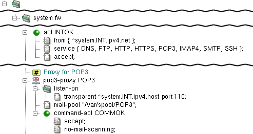
pop3-proxy is the proxy daemon for Post
Office Protocol version 3 (RFCs 1939, 2449, 1734). The proxy supports
secure communication via the SSL/TLS protocols.
The proxy is configured in the pop3 section.
In the sample configuration depicted in Figure 4.20, “POP3 Proxy”,
the proxy-user and chroot-dir items
define the operating-system-level user, under which the proxy should run,
and the directory, in which it should be chrooted. The proxy listens
transparently for requests at Kernun UTM's internal address at port 110
and, again, the proxy must be referenced by at least one ACL in the
system section.
The mail-pool item defines the directory,
in which the mails are temporarily stored by the proxy. Note that this
directory must be created manually by the administrator and that it
must be writable by proxy-user. Note also that the
directory can be the shared by smtp-proxy,
imap4-proxy and pop3-proxy (or by
any combination of them).
pop3-proxy uses three-phase ACLs. The first phase,
session-acl, is checked once for each client connection.
It permits or denies client access and sets some connection parameters.
The second phase, command-acl, is also checked once for
each connection, but it can be selected according to the client
certificate if SSL/TLS is enabled by session-acl.
Various parameters can be set in command-acl, e.g.,
the permitted sets of POP3 commands and capabilities, timeouts, SSL/TLS on
the server connection. The third-phase ACLs are used only if mail
processing is enabled in command-acl. Two types of
these ACLs exist. mail-acl is checked once for each mail
transferred from the server to the client. It defines rules of the acceptance
or rejection of the mail according to its content and antivirus/antispam
test results. doc-acl is checked once for each document
(MIME part) of a mail. It defines document processing, e.g., filtration
or replacement by a fixed file. See mod-mail-doc(5).
In this example, the no-mail-scanning item in
command-acl COMMOK defines that no mail scanning is to
be performed. In this context, as the POP3 protocol is intended only for
download of e-mails, it means that the downloaded mail is not even opened.
Were the no-mail-scanning item absent, the mail
would be stored and unfolded to headers and attachments, etc., and
various tests could be performed on any part. This alternative will be
discussed in Section 15, “Antivirus Checking of Data” and Section 16, “Antispam Processing of E-mail”.
In the previous section we described the initial configuration as generated by the configuration script during the first boot after the installation of Kernun UTM. In this section we will demonstrate how to modify the configuration. We will make the following changes:
enable dns-proxy;
enable http-proxy;
restrict HTTP to a subset of the internal network;
allow only the HTTP method
GET.
First of all, we want to permit the HTTP traffic. As the transparent mode of the proxy is used, the clients connect directly to servers. Therefore, the clients must be able to resolve server addresses, which is why we need to enable DNS as well. The following steps produce a working configuration with the required changes.
Start the GUI and connect to Kernun UTM, as described in Section 1.1, “Kernun GUI Launcher”. If Kernun UTM is running the unmodified initial configuration, you will see the GKAT window with only a few components running, as depicted in Figure 4.21, “The Kernun UTM running the initial configuration”.
Select in the menu to open the configuration.
In the left-hand part of the configuration window, look for a line containing
hidden dns-proxy DNS. Select the line with the left mouse button, then click the right mouse button to open the context menu and select . The line will change todns-proxy DNS.Repeat the same action for the line containing
hidden http-proxy HTTP.Select the line
acl INTOKand then select from the context menu. In the Create Item/Section dialog, selectaclas the type of the section and set the section's name, for exampleNET1_DENY. You have created a new global ACL.Now select the newly created ACL and use from its context menu repeatedly to add the
from,service, anddenyitems.Select the
fromitem. In the right-hand part of the configuration window you can see the current value of the item, which is the empty set. Add a new value to the set by clicking on the button . Enter the address (with mask) of the subnet that is to be denied, for example,[192.168.10.128/25].Select the
serviceitem. Using , addHTTPto the list.Now we have the new ACL denying access from a subnetwork ready. However, as the ACLs are checked in sequence and the first matching is used, we must exchange our two ACLs. This can be done in several ways. One possibility is to select
acl NET1_DENYand click on in its context menu.Finally, we want to restrict the
HTTPproxy to allow only theGETmethod. Open thehttp-proxy HTTPsection by clicking on the small plus sign. Select therequest-acl ALL2line.Add a
request-method { GET }item to this ACL in the same way as when you modified values inacl NET1_DENY.The configuration should now correspond to Figure 4.22, “The modified configuration”.
Save, generate, and apply the configuration by selecting . The Commit configuration window is displayed, as depicted in Figure 3.17, “Configuration commit dialog”.
Click to enter a RCS log message with a description of the change you have made.
The configuration is saved to Kernun UTM, recorded as a new version in the RCS file, the low-level configuration files are generated and applied (copied to the locations where Kernun UTM components will look for them).
The Synchronize system with configuration window is displayed, as depicted in Figure 4.23, “Activation of the new configuration”. It informs you that components
DNSandHTTPhave been reconfigured and need to be started for the new configuration to take effect.Click in the synchronization dialog to finish the reconfiguration; Kernun UTM now contains running DNS and HTTP proxies, see Figure 4.24, “Reconfigured Kernun UTM is running”.
Now you can switch to the Log page of the Proxies node in the GKAT window. If you start a Web browser on a machine in the internal network and try to access a Web server in the external network, you will see proxy log messages appearing.
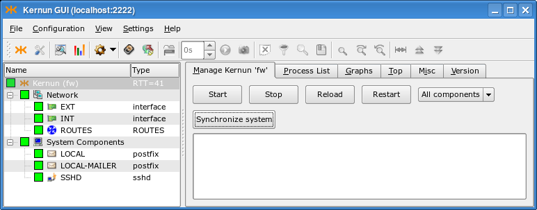
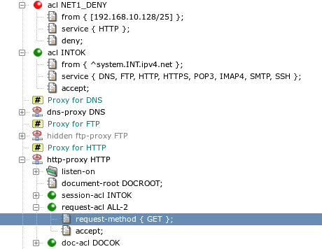
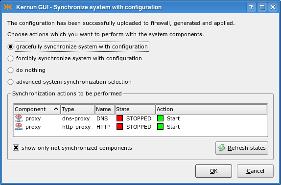
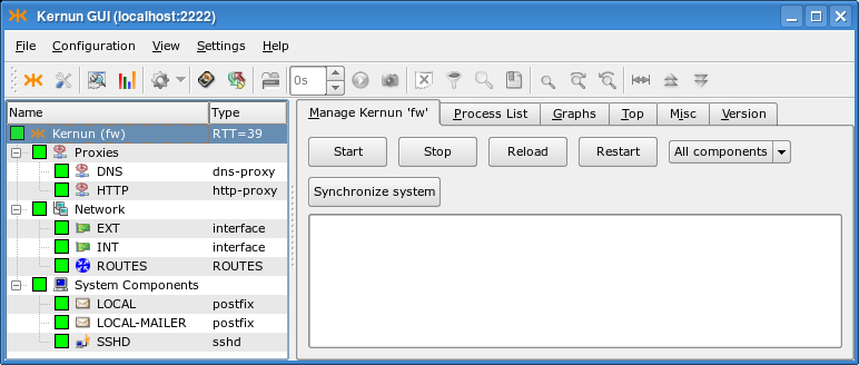
The process of adding new TCP proxies can be simplified even more using two wizards (for general information on wizards, see Section 1.4.6, “Configuration Wizards”). When creating a TCP proxy, you first need to decide whether you want to enable the connection of clients in the internal network to a server in the external network (the server must have a public IP address and the clients connect to this address), or whether you have a server in the internal network (with a private IP address) and clients from the external network will connect to Kernun UTM, which will forward them to the server. The Kernun GUI provides one wizard for each of the alternatives. The following subsections describe the creation of sample proxies in both cases.
As we have said before, a proxy needs to be created in order to allow
communication from the internal to the external network. The proxy should be
transparent, which means that clients in the local network would not be aware of the fact
that they do not connect directly to the server. The TCP proxy to external network wizard
will lead you through the creation of the transparent TCP proxy.
In this example, we will configure the transparent tcp-proxy
to allow some privileged local clients to shop on www.ebay.com.
First of all, you need to delete or hide the
tcp-proxy HTTPS from the initial configuration,
because it would collide with the proxy we want to create. Then
select to start the wizard.
On the first page, you are asked to choose the
tcp-proxy section name, the interface
to the network that contains the clients and the port of the service that is
supposed to use the proxy. In our example, we choose the INT
interface and the 443 port, as shown in
Figure 4.25, “TCP proxy general network settings”.
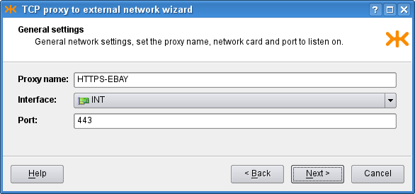
On the second page, you define the clients in the internal network
that are allowed to connect using this proxy and the servers in the external
network, to which the clients may connect, in the form of either IP addresses
or host names. If you already have an appropriate ACL created in the
configuration, you may select the Use existing accepting ACL
radio button and then choose the ACL to be used for this proxy. As we do not
have any usable ACL in the system, however, we choose to create a new
one, and set its name and the IP address of the privileged client that is
allowed to log in to the ebay.com server. The configuration is
depicted in Figure 4.26, “TCP proxy ACL settings”.
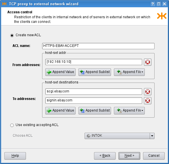
The third page contains more advanced connection settings, including several connection timeouts and a limit of the number of proxy children. If you do not fill in any of these fields, the corresponding item will not be included in the resulting configuration. Since we know that there will be no problems with the traffic load, we leave all the limits empty. In order to get more detailed traffic examination outputs, we choose to monitor the proxy (which i.a. produces graphs of the proxy usage, see Figure 3.8, “Graphs page”) and to generate proxy statistics (see Figure 5.26, “Statistics browser window”). The filled page is shown in Figure 4.27, “TCP proxy miscellaneous settings”.
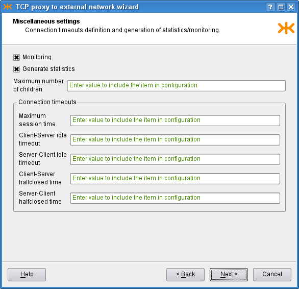
Finally, the last page (Figure 4.28, “TCP proxy recapitulation”) shows
the recapitulation of the wizard settings in the form of the text configuration
that is to be added to the main system configuration. There is also the
outcome of system verification of the configuration with the created proxy.
You can click Finish to commit the proxy into the configuration,
Back to return and modify the wizard settings, or
Cancel to close the wizard and discard all the settings.
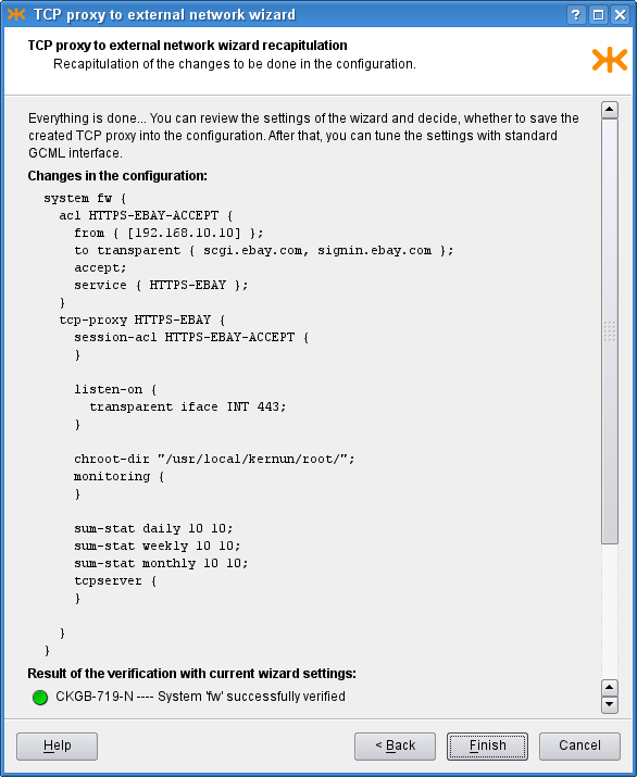
Besides the above-mentioned wizard for a transparent proxy,
the Kernun GUI also provides a wizard for a non-transparent tcp-proxy.
In this case, clients connect to to a specified port at Kernun UTM, which
forwards the communication to a server behind it. This is useful when
creating servers without a public IP address in the internal network (which
is a recommended practice). We will create an IMAP4S proxy that will
allow employees at home connect to a mail server in the internal company network behind
Kernun UTM and read their mail. The wizard is very similar to the
Section 3.1.1, “TCP Proxy to Server in External Network” wizard; actually, only the second page
differs.
On the first page, we choose the proxy name, the interface on which
it is supposed to listen (this time, it is the external interface
EXT) and the port for secure IMAP4, 993.
On the second page, we similarly define the ACL, with a slight difference
in the process of its creation. We only define restrictions concerning
clients, as they always connect to Kernun UTM.
After choosing the ACL, we need to specify where to plug the
communication in (in our case the IP address of the IMAP4S server) and the port
it listens on. This is specified in a single field as
[192.168.10.7] : 993. Furthermore, we want the server to receive
packets with the original client's IP address (rather than that of Kernun UTM), so we
check the Client source address check box. The second
page is shown in Figure 4.29, “Non-transparent TCP proxy ACL settings”.
The last two pages are the same as in the transparent proxy wizard.
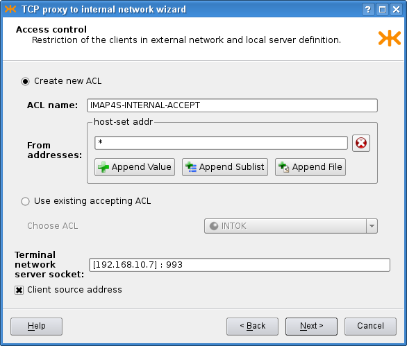
[17] They are mainly
proxy configuration files and some system configuration files, e.g.,
/etc/rc.conf.
[18] All relative paths here are relative to the
configuration directory
/usr/local/kernun/conf.
[19] Sections
shared-file are created at the global level of the
configuration file.
[20] For the present, you can ignore the section
smtp-forwarder. It will be discussed later, together with
the smtp-proxy.
[21] In fact, such sessions do not even begin regardless of ACLs, because the proxies are configured to listen on the internal interface only.
[22] Moreover, some items can be configured at both levels. The proxy-specific one takes precedence in that case.
[23] In particular, mail sent from the internal network addressed to someone outside the local network.
Table of Contents
- 1. Packet Filter
- 2. System Configuration
- 3. Caching Name Server
- 4. DNS and DHCP Services
- 5. Time Synchronization with NTP
- 6. Monitoring of Kernun UTM Operation
- 7. Networking in Proxies
- 8. H.323 Proxies
- 9. SIP Proxy
- 10. SQLNet Proxy
- 11. UDP Proxy
- 12. Cooperation of HTTP and FTP Proxies
- 13. Secure Communication Using SSL/TLS
- 14. User Authentication
- 14.1. Authentication Methods
- 14.2. Authentication in FTP Proxy
- 14.3. Basic Authentication in HTTP Proxy
- 14.4. Kerberos Authentication in HTTP Proxy
- 14.5. Kerberos Authentication in Transparent HTTP Proxy
- 14.6. NTLM Authentication in HTTP Proxy
- 14.7. HTTP Authentication Proxy
- 14.8. Out of Band Authentication
- 15. Antivirus Checking of Data
- 16. Antispam Processing of E-mail
- 17. Content Processing
- 18. Filtering HTTP Requests by URI
- 19. HTTPS Inspection
- 20. Adaptive Firewall
- 21. Traffic Shaping
- 22. Virtual Private Networks — OpenVPN
- 23. Virtual Private Networks — IPsec
- 24. High Availability Clusters
- 25. Kernun Branch Access
- 26. IPv6
- 27. Honeypot
This chapter covers the configuration of various advanced features of Kernun UTM. You can find here instructions on how to configure each feature, along with the description of the most important configuration parameters; the remaining ones are listed in the relevant parts of the reference documentation. It is assumed that you know the principles of the Kernun UTM configuration and how to use the Kernun GUI. If not, consult Chapter 4, Configuration Basics and Section 1, “Graphical User Interface”.
In addition to the application layer control, Kernun UTM includes a TCP/IP packet filter with advanced features, such as stateful filtering, network address translation (NAT), traffic normalization, traffic shaping, OS fingerprinting etc. This section offers a general overview of the packet filter's capabilities, as well as examples of a few typical packet filter configurations[24].
It is very important to consider the way packets are handled in Kernun UTM. When combining packet filter rules, traffic shaping and application proxy access control lists, we need to take into account the order, in which network traffic is processed by individual components of the system.
Upon entering the system, network packets get inspected by the packet filter at first. The packet filter itself consists of a number of components. The order, in which these components handle network traffic, is always the same:
State engine
Traffic normalization engine
Traffic shaping / queuing engine
Network address translation engine
Packet filtering engine
This order applies to both incoming and outgoing traffic, i.e. it is the same whether the packet is entering or leaving the system. As regards incoming packets, application proxies may take control only after they are processed by all the packet filter engines. On the other hand, traffic originated at application proxies goes through packet filter engines and then leaves the system for the network.
Important
Network address translation rules always create states. If an initial packet of a connection is translated by an NAT rule and then passed by the packet filter, it is automatically also passed on its way back, thanks to the created state.
As for packet filtering, states are created only if the rules explicitly
specify so using the keep-state modifier. However, if the
raw packet filter rule is specified, the state is kept by default;
if you do not want to keep the state in such a case, you need to add
no state to the raw rule.
The packet filtering rules are defined in the
system.packet-filter section. The following list
introduces its items and subsections:
set-option— a repeatable item containing packet filter specific options, see pf.conf(5);timeouts— a non-repeatable section defining various filter timeouts;altq— the specification of traffic shaping rules, which assign the traffic to individual queues defined in thesystem.pf-queuesections;scrub-acl— the traffic normalization rules; by default, all incoming traffic is normalized and IP fragments are reassembled;rdr-acl— redirection NAT rules, applied to incoming traffic, change the destination address;nat-acl— mapping NAT rules, applied to outgoing traffic, modify the source address;binat-acl— bidirectional NAT rules combine both redirection and mapping;filter-acl— packet filtering, either unidirectional or bidirectional rules (both stateless and stateful);load-anchor— loading of rule subsets from files.
In the following sections we go through several typical
configuration examples that involve capabilities of Kernun UTM's packet filter.
We will start with the initial configuration as described in Section 2, “The Initial Configuration”. The resulting packet filter configurations
can be found in the configuration sample file packet-filter.cml in the
/usr/local/kernun/conf/samples/cml directory.
Packet filtering basically means controlling (either passing, or blocking) network traffic based on basic TCP/IP attributes, including the source and destination IP addresses and ports, the network interface the packet emerges on, its direction (inbound or outbound), and a few other protocol-specific characteristics.
Important
Even if the traffic is passed by the packet filter, there must exist an application proxy with an ACL permitting the communication; otherwise, it is denied. In other words, Kernun UTM does not forward network packets, but instead, it attempts to transparently grab them and process them with application proxies. However, the mechanism of traffic grabbing by application proxies can be bypassed, as described in Section 1.4, “Selective Packet Forwarding”.
Note
By default, the packet filter rules allow all traffic, but there is only a limited set of application proxies in the initial configuration, see Section 2, “The Initial Configuration”.
Blocking traffic using the packet filter may be useful in many situations. For example, we may relieve application proxies of the burden of processing traffic that we know for certain is undesired. Also, application proxies always grab connections, and only then they may selectively deny them. This means that the connection is always established at first, and then immediately closed if denied by a policy. It may be advantageous to pretend to some clients that there is no application proxy in the way, which can be achieved by resetting those connections using the packet filter. Furthermore, there are antispoofing rules to block traffic with faked source addresses, see Section 1.3, “Antispoofing Using Packet Filter”, and it is possible to bypass the application proxy processing and forward some traffic directly to its destination, see Section 1.4, “Selective Packet Forwarding”.
Individual packet-filtering rules are located in filter-acl
subsections within the system.packet-filter configuration section.
The most important items in filter-acl are summarized
here:
from— A set of hosts, addresses and networks that the packet's source address must match. Optionally it may also include constraints concerning source TCP/UDP ports. If omitted, all source addresses and ports match.to— The set of hosts, addresses and networks that the packet's destination address must match. Optionally it may also include constraints concerning destination TCP/UDP ports. If omitted, all destination addresses and ports match.iface— The network interface that this rule applies to. Moreover, the direction of communication may be specified, eitherinfor inbound traffic oroutfor outbound traffic. If this item is not present, the rule applies to all network interfaces and all directions.protocol— The IP protocol that this rule applies to. Protocols are accepted with their symbolic names, such asicmp,udp,tcp, oresp. Moreover, a shortcuttcp-udphas been added for user comfort, meaning both the TCP and UDP protocols. Similarly, the shortcutesp-ahis interpreted as both the ESP and AH protocols[25]. Additional protocol-specific parameters are available for the ICMP and TCP protocols, specificallyicmp-typeto match the ICMP message type, andflagsto match the TCP flags field.deny / accept— Thedenyitem blocks traffic; theacceptitem is used to pass it.keep-state— This item lets the packet filter create a state for the connection as a packet is passed. The following packets in the same connection will then be handled in exactly the same way as the first one, without the need to search the ruleset. Another advantage is that packets of the same connection in the opposite direction are implicitly passed.
Important
Port specification is available only for the TCP and UDP protocols.
Thus, if a port constraint is present in a from or
to item, the protocol item must be specified
and must be one of tcp, udp, or
tcp-udp.
Example: If we want to block the traffic coming in on our external
interface to the TCP port 22, we shall use the to,
iface and deny items, as shown in
Figure 5.1, “A simple blocking packet filter rule”.
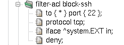
The deny part of the rule means that Kernun UTM will
silently discard packets coming in to port 22. However, this behavior is not very
effective, for several reasons. First, everyone knows that there is
a filter blocking those connections, and that can attract unwanted attention.
Furthermore, the standard application will not give up if there is no response to
its connection attempts. Therefore, it is customary to send back
information that the port is closed. We will do so by adding a
return item to our filter rule, see Figure 5.2, “A blocking packet filter rule with return”.
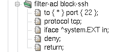
Tip
We can change the packet filter's default behavior of silently
discarding packets by setting the block-policy return option.
If we do so, it will properly react to blocked ports as if those ports were
closed even if there are no return items in individual rules. See
an example in Figure 5.3, “Option block-policy instead of return in rule”.

Should some specific clients be allowed to connect to port 22, we have to add a packet filter rule before the blocking rule we have just created. Rule evaluation abides by the so-called first-match principle. This means that rules are evaluated in the order, in which they appear in the configuration, and as soon as a matching rule is found, the evaluation stops and the remaining rules are ignored. Therefore, more specific rules must precede those with more generic matching criteria. Figure 5.4, “More specific rule must come first” shows how to add a rule allowing connections to port 22 to a set of IP addresses, preserving the default behavior of blocking port 22 to other clients.
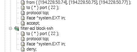
IP address spoofing is an attack based on counterfeiting the source IP address in order to confuse another computer system. It may be extremely dangerous if attackers from the outside pretend to have an internal source IP addresses; although they never get a response back, it may be sufficient to perform a successful denial-of-service or another kind of attack.
The goal of antispoofing is obviously to prevent spoofing attacks. We can stop intruders from the outside who pretend to have an internal source IP address quite easily. In general, internal network addresses can appear as the source of communication only on the internal network interface. As there may exist more than one protected network interface, this rule can be applied to other networks and interfaces as well.
A simple antispoofing rule consists of interface specification
followed by the antispoof and deny items, see
Figure 5.5, “Simple antispoofing rule”. In effect, the internal network
192.168.10.0/24 is blocked when
it appears as a source IP address on any other interface than INT
[26].
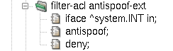
This simple antispoofing rule works for networks directly connected
to named interfaces. However, if our internal network is not flat, but
consists of several routed networks instead, we need to involve all the
internal networks in antispoofing. This can be achieved using the routes
modifier in the antispoof item. The resulting rule is depicted
in Figure 5.6, “Antispoofing rule including routes”.
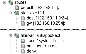
Note
The routes modifier has an effect
only if there are some routes within the internal network.
To illustrate this fact, the sample configuration file
packet-filter.cml introduces a second internal network,
192.168.11.0/24, specified in
the routes section. Now, both our internal networks,
192.168.10.0/24 and 192.168.11.0/24, get blocked in the source
address field on all interfaces except the internal interface
INT.
Standard routers and filtering gateways accept all network datagrams, and if they are destined for another host, they send them out in accordance with the system's routing table. This mechanism is known under the name forwarding.
Kernun UTM does not forward network packets by default. Only traffic either destined for the system itself or grabbed transparently by application proxies will find its way through; everything else is thrown away. See transparency(7) for more detailed information.
It is possible to bypass application proxies and control the
communication only with packet filter rules. To do so, we need to inform
the transparent grabbing system which packets should be left untouched.
For that purpose, a special tag NOTRANSP has been introduced.
Note
Tagging is a feature of the packet filtering engine; network packets can be assigned a string value that will accompany those packets on their way through the network stack. Other Kernun UTM components may then check which tags, if any, are assigned to traffic they are processing.
Important
The tag name NOTRANSP that the
transparency engine uses to recognize bypassing packets is configurable.
By changing kernel sysctl variable net.inet.ip.no_transp_tag,
we can define another tag string to be used to distinguish between standard
transparent proxy traffic and bypassing datagrams. Sysctl variables (also
called MIBS) are configured in system.sysctl
configuration section, see Section 2.6, “Kernel Parameters in /etc/sysctl.conf”.
To assign a tag to packets, add a tag item to
a filter-acl rule inside the packet-filter section.
Figure 5.7, “Selective packet forwarding rule” illustrates a rule causing the packet flow
between two hosts to bypass transparent proxy processing, forwarding them
directly to the network in accordance with the system routing table. Note that we have
introduced a new interface, DMZ, representing a demilitarized zone with
public accessible servers. The rule bypass-int-dmz
permits bidirectional traffic between an internal host and a host in the DMZ.
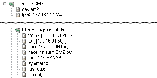
Apart from tag, two more important filter-acl
items are introduced in the sample rule bypass-int-dmz
depicted in Figure 5.7, “Selective packet forwarding rule”:
:
fastroute— This option means that packets get forwarded through Kernun UTM to their destination. It is called selective packet forwarding, as opposed to global forwarding, which is performed by the standard routers and packet filtering gateways. Withoutfastroute, packets taggedNOTRANSPwould not reach their destinations.symmetric— Adds a second rule, allowing traffic in the opposite direction on the same interface. Source and destination IP addresses are swapped in the second rule, as well as the traffic directioninorout. Considering the fact that we have two interface specifications in the rule, we end up with four individual packet flow permissions:Incoming packets on interface
INTgoing from192.168.1.20to172.16.31.50(the basic rule foriface ^system.INT in).Outgoing traffic on interface
INTreturning back from172.16.31.50to192.168.1.20(the symmetric rule foriface ^system.INT in).Outgoing packets on interface
DMZoriginated at192.168.1.20and destined for172.16.31.50(the basic rule foriface ^system.DMZ out).Incoming datagrams on interface
DMZtraveling from172.16.31.50to192.168.1.20(the symmetric rule foriface ^system.DMZ out).
Important
If a packet filter rule sets the NOTRANSP tag for
a packet, a state is automatically created for the packet. This accepts
all following packets of the same connection in both directions. If we
want to selectively forward some communication via the
NOTRANSP mechanism without creating a state, we need to add
an explicit rule that matches the packets and does not contain
keep-state.
There are three types of NAT rules: mapping rules (nat-acl),
redirection rules (rdr-acl) and bidirectional NAT rules
(binat-acl).
Mapping changes source IP addresses (and often ports) of outgoing packets. It always applies to outbound traffic, but it also creates states for backward incoming communication. The state engine fully recognizes individual TCP connections, UDP sessions and ICMP control messages that belong to them. Hence, if a state is created, only legal communication is passed and translated forth and back.
The nat-acl sections allow for a similar set of
items as filter-acl rules. The item from
is used to match source IP addresses and ports, similarly to
is matched against destination IP addresses and ports. The interface
specification may not include the in/out direction as
mapping rules apply only to outbound traffic. The deny
modifier does not block traffic, but effectively denies any NAT mapping if
matched.
A new important item is introduced for mapping rules:
map-to. Its purpose is to specify the final address
and port combination after the translation.
A sample mapping rule is depicted in Figure 5.8, “Mapping NAT rule”.
It illustrates the use of the map-to item; it
specifies an IP address (using a reference to the outgoing interface's address
^system.DMZ.ipv4.host) and a port (0 in our example,
meaning any port number available).
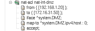
As always, mapping rules are implemented using the first-match
principle, i.e. the first matching rule is applied immediately, without
consulting the rest of the nat-acl rules.
Unlike mapping, redirection deals with destination IP addresses and ports. Redirection rules are thus applied to the inbound traffic, creating states. The same powerful state engine is in charge of matching backward outgoing packets and changing their addresses and ports back to their original values.
Apart from the target redirection address and port combination,
which is specified using the rdr-to modifier, all other item
names and features are the same in mapping and redirection rules. The
example in Figure 5.9, “Redirection NAT rule” assumes connections from the
172.16.31.0/24 network,
destined for the DMZ interface's local address 172.16.31.1 and port 80. Those
connections get redirected to internal server at 192.168.1.20, port 80.
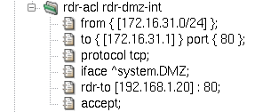
Imagine that we have an NAT network and want to bypass Kernun for some traffic
(e.g. ICMP packets, in order to be able to ping to the internet from the local
network). For that special case we need to create an NAT rule for the NAT and, at the same time,
tag the traffic with the NOTRANSP tag to forward it, rather than give
it to Kernun's proxies. The NAT rule automatically creates a state, so the reply to the
ping should be delivered to the requester without the need to add any other rule.
However, there is a catch in the PF implementation. The NOTRANSP tag in
combination with NAT rule gets lost and the returning packet is passed to Kernun, rather
than forwarded. For this case, Kernun automatically generates a rule pass any
to any tagged NOTRANSP no state tag NOTRANSP in the pf.conf file, in order
to keep the tag. This rule permanently stores the NOTRANSP tag to the
state of the tagged packet and is not applied to any other packets.
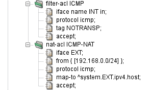
Figure 5.10, “Forwarding of ICMP Packets over NAT” shows a configuration of selective forwarding
of ICMP packets on Kernun UTM for clients behind NAT. The filter-acl ICMP
section tags the packet by the NOTRANSP tag to be passed through Kernun without giving
it to the proxies, while the nat-acl ICMP-NAT rewrites the addresses
and creates a state for the reply packets to be passed back. The returned packets are
first NATed, then the above-mentioned rule is applied and restores the NOTRANSP tag, and
the packet is therefore forwarded into the local network.
The packet filter, together with the network stack in the operating system kernel, provide some means for defense against Denial of Service (DoS) and Distributed Denial of Service (DDoS) attacks. Such attacks try to overload a target computer system or network by sending huge amount of traffic. A DoS attack is originated from a single malicious computer. A DDoS attack is similar, but data are sent by many computers at the same time. It allows the attacker to magnify the number of network packets many times in comparison with a single-origin DoS, hence making the effect on the target network worse and any defense harder.
Basic protection against some (D)DoS attacks on the transport layer of the TCP/IP is built into the network stack of the operating system kernel in form of the SYN cache and SYN cookies. They are effective especially against the SYN flood attack, when the attacker sends many TCP connection requests in the form of TCP SYN segments. The SYN cache keeps information about TCP connection handshakes that have not been completed yet. A SYN cache entry occupies less memory than the full state record of an established TCP connection. Hence the system is able to withstand much more SYNs. SYN cookies take one step further, keeping no state and encoding all information necessary to complete the handshake into the SYN/ACK segment sent to the client.
The SYN cache is always enabled. By default, SYN cookies are also
enabled. They can be disabled by setting the sysctl variable
net.inet.tcp.syncookies=0, see Section 2.6, “Kernel Parameters in /etc/sysctl.conf” for instructions on setting sysctl
variables. SYN cookies are used when the SYN cache becomes full. It is
possible to disable the SYN cache and use only SYN cookies by setting the
sysctl variable net.inet.tcp.syncookies_only=1.
The SYN cache and SYN cookies protect only against SYN flood attacks on TCP-based application protocols handled by a proxy or by a server running locally on the Kernun system. Additional defenses are provided by the packet filter. They are effective for communication handled by the packet filter and not passing via any proxy, but can be combined with a proxy, too. They can also block attacks that perform full TCP handshake and then send excessively large volumes of application-layer data in order to overload a server.
The packet filter allows limiting numbers of simultaneous connections that match a filtering rule or originate from a single source addres. The limits are configured by adding per-rule options. There are two variants how to create such packet filter rules:
A
filter-aclis created with itemkeep-state. A raw option is added by itemoptioncontaining limit specifications delimited by comma, for example,option "keep state (source-track rule, max-src-nodes 100)". Note that “keep state” is specified here, in addition to the separatekeep-stateitem.A
filter-aclis created containing the whole packet filter rule written in arawitem, for example:pass quick inet proto tcp from any to any keep state (max 100)
Available limit specifications are:
maxnumberIt limits the maximum number of simultaneous states (connections) the rule may create. When this limit is reached, further connection attempts are silently dropped. New connections are allowed only after some of the existing states time out. Note that a state times out some time after the related connection is closed.
source-track ruleEnables counting the states created for each individual source IP address. The per-IP limits (e.g.,
max-src-nodesandmax-src-states) are compared to the number of states created by this rule.source-track globalEnables counting the states created for each individual source IP address. The per-IP limits are compared to the sum of states created by all rules that use this option.
max-src-nodesnumberIt limits the maximum number of distinct IP addresses that can have states at the same time.
max-src-statesnumberIt limits the maximum number of states that can be created for a single source IP address.
max-src-statesnumberIt limits the maximum number of established TCP connections that can be created for a single source IP address. In contrast to
max-src-states, this option counts only connection that completed the 3-way TCP handshake.max-src-conn-ratenumber/secondsIt limits the rate of establishing new TCP connections over a time interval.
overload <,table>overload <,table> flushoverload <table> flush globalIf a source IP address reaches one of the limits
max-src-connormax-src-conn-rate, it will be added to a named packet filtertableflushis used, all states created by the matching rule and originating from this IP address will be deleted, effectively terminating all existing connection from the offending IP address. Ifflush globalis used, all states from this IP address are deleted, regardless the rule that created them.
Example: The following rules will block any IP adress that initiates more than 100 HTTP connections per second.
table <dos_attack> persist
block quick from <dos_attack>
pass in proto tcp from any to any port 80 keep state \
(source-track rule, max-src-conn-rate 100/1, overload <dos_attack> \
flush global)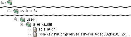
Additional user accounts can be allowed access to the system in the
configuration. Each user is represented by a user section
within the users section. The user section must
contain a role item with a value admin or
audit. The admin class has full access
to the system and permissions to configure and operate all Kernun UTM components.
The audit class can only view the system configuration and
logs. The user section can also contain a
ssh-key item, which generates a corresponding line in the
.ssh/authorized_keys file for the user's ssh key.
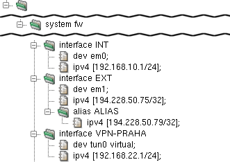
The Kernun UTM configuration can hold any number of
interface sections that correspond to a physical
device. Virtual network interfaces can be created from other tools
than Kernun UTM configuration utilities; these, however, need to be referenced in
the Kernun UTM configuration. For example, an instance of openvpn
creates the tun0 interface when started. To be able to
use it in the Kernun UTM configuration, include the virtual parameter
in its dev item (as illustrated in the interface
VPN-PRAHA section in Figure 5.12, “Network Interfaces”).
Such an interface is not generated in the rc.conf
file.
An interface can be assigned multiple IP addresses.
To do so, add an arbitrary number of alias sections
to the interface section. Each of them
must contain an ipv4 item that defines its IPv4 address,
as depicted in Figure 5.12, “Network Interfaces” in
interface EXT.
See interface(5) for details.
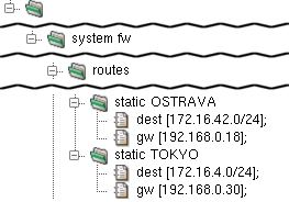
Static routes provide the capability to explicitly route packets
for a given network to a static machine, which works as a gateway for
this network when this cannot be done automatically by
the system routing table management daemon (such as
routed). See
route(8) for further info.
A static route is set by a static section in
the routes section. The static section
must contain one dest item — the routed network
address — and a gw item — the address of
the gateway machine for the routed network.
Kernun UTM supports dynamic IP routing via BIRD's (The BIRD Internet Routing Daemon) implementation of OSPF (Open Shortest Path First) protocol. It allows routers to automatically change routes, so that the path remain functional in case of failure of an router in the path.
BIRD uses separate configuration for IPv4 and IPv6. In the
example below, bird4 defines rules for IPv4 routing of
one Kernun UTM in the role of router. This router would be one of multiple
routers in network, either Kernun UTM or any other device that supports
OSPF. For example, two clusters of Kernun UTM with all nodes connected with
each other via VPN.
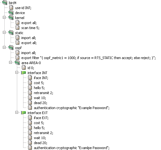
BIRD, or more precisely OSPF, requires each router to be
identified by an unique ID. use-id in the example
above, uses IPv4 address of interface INT as this ID. The sections
device, kernel,
static and ospf defines different
protocols (or pseudo-protocols) which BIRD should use for import or
export of routes. The device protocol is not a real
routing protocol. It doesn't generate any routes and it only serves as
a module for getting information about network interfaces from the
kernel. Except for very unusual circumstances, you probably should
include this protocol in the configuration since almost all other
protocols require network interfaces to be defined for them to work
with. The kernel is also a pseudo-protocol. Instead of
communicating with other routers in the network, it performs
synchronization of BIRD's routing tables with the OS kernel.
Basically, it sends all routing table updates to the kernel and from
time to time (item scan) it scans the kernel tables to
see whether some routes have disappeared or whether a new route has
been added by someone else. The section static
analogically sets rules for static routes defined in
system → routes →
static.
The ospf section defines, besides import/export
rules, one or more areas (area). In OSPF, the network
is divided into areas that are logical groupings of hosts and networks.
Each area maintains a separate link state database whose information
may be summarized towards the rest of the network by the connecting
router. Thus, the topology of an area is unknown outside of the area.
This reduces the routing traffic between parts of an autonomous system.
An area is identified by it's id. "O" in this example,
identifies backbone area (or area 0.0.0.0) which forms the core of an
OSPF network. In interface sections we assign
different properties for selected network interfaces. Especially, the
cost item. The OSPF routing policies for constructing
a route table are governed by link cost factors associated with each
routing interface. Cost factors may be the distance of a router
(round-trip time), data throughput of a link, or link availability and
reliability, expressed as simple unitless numbers. Other items defines
different rules for communication with other routers via given network
interface.
For more information on BIRD configuration see http://bird.network.cz/?get_doc&f=bird-3.html
The /etc/rc.conf configuration file is
used to automatically perform various actions at the system startup. It
contains information about the configuration of network interfaces, the
services that should be started after a boot and optionally their parameters,
the configuration of the machine's host name, console settings, etc.
See rc.conf(5) for details.
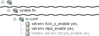
The rc.conf file is generated by Kernun UTM and
should therefore not be configured directly, but in
rc-conf section of the Kernun UTM configuration. An entry in
rc.conf is set through the set-env
item. Examples of useful items include set-env fsck_y_enable yes
(which will make fsck answer itself "YES" to all
questions and thus make automatic OS booting possible).
It is even possible to extend an already set value by redefinition,
such as set-env variable "$variable ...".
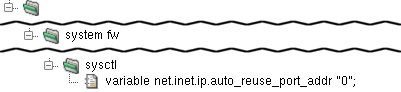
The /etc/sysctl.conf file is read when the OS
enters the multi-user mode and sets default settings for the kernel. Its
contents are generated from the variables items in the
syctl section. Each variable sets
one kernel setting. For example, variable
net.inet.ip.forwarding "1" turns on IP forwarding.
The crontab is the configuration file for
the cron daemon, which runs selected commands
periodically. Each entry in crontab contains
seven fields separated by a white space character:
minute — permitted values: 0-59
hour — permitted values: 0-23
day of month — permitted values: 1-31
month — permitted values: 1-12 (or names)
week — permitted values: 0-7 (0 or 7 is Sun, or use names)
user — user under whom the program should be run
command — the command to be run and its parameters
A field may be set to "*", which stands for its entire range. Numerical ranges, lists and their combinations are also allowed. For example, "3-7", "1,2,7,8", "1-3,8-14,20". Step values and more complex expressions can be used as well, see crontab(5) for details.
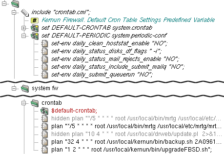
There is a sample crontab configuration in
samples/include/crontab.cml. It can be included
in crontab by the application of the
$default-crontab variable, which is set in
include samples/include/crontab.cml.
Additional entries can be set by plan items
in the crontab section. For example plan
"1 2 * * * root
/usr/local/kernun/bin/upgradeFBSD.sh" will schedule
the script upgradeFBSD.sh (which automatically
synchronizes and compiles the OS source) to be run every day at 02:01 under
the user root.
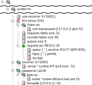
Kernun UTM's dns-proxy is not designed to be used as a
name server — it does not cache DNS queries. A possible solution
is a combination of named and dns-proxy.
In this scenario, named listens for DNS queries on the internal
interface and provides the cache. It queries dns-proxy
that is bound to the loopback interface and, in accordance with ACLs, permits or
denies the query, sends a response or queries the DNS root servers.
The configuration in Figure 5.18, “Caching Name Server configuration” shows the
named daemon configured in the nameserver
section to listen on Kernun UTM's internal address on port 53
(listen-sock ^system.INT.ipv4.host : 53), while Kernun UTM uses it
as its resolver (server ^system.INT.ipv4.host : 53 in
the resolver section). dns-proxy is bound to
the loopback interface by the non-transparent [127.0.0.1] : 53 item in the
listen-on section of dns-proxy. See
named.conf(5) for more details.
The other typical scenario is that one or more name servers exist in the internal network. In this situation, clients are configured to query the server in the internal network, which queries dns-proxy that is configured to listen on the internal address, while Kernun UTM itself uses the internal name server as its resolver.
Note that in both of these scenarios it is necessary to have multiple name servers running in order to provide different DNS responses for different clients, because the response is cached on the name server and therefore not matched against the ACLs of dns-proxy. Nevertheless, it is always possible to plug requests coming from particular clients to a host with a different IP address, ignoring the DNS name in the request for every service.
In this scenario, named listens for DNS queries on the internal interface and queries dns-proxy, which provides the response.
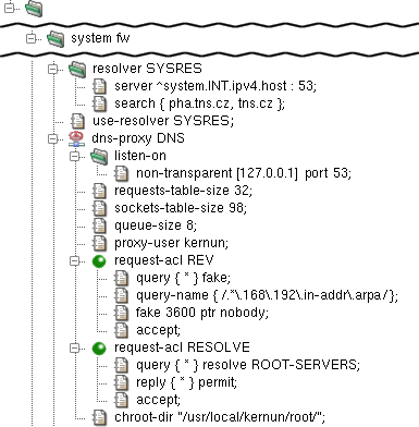
The configuration in Figure 5.19, “DNS Server - Proxy configuration” shows
Kernun UTM using named as the resolver (server
^system.INT.ipv4.host : 53 in the resolver section).
dns-proxy is bound to the loopback interface by
non-transparent [127.0.0.1] : 53 in the
listen-on section of dns-proxy.
See Section 3, “Caching Name Server” for further information.
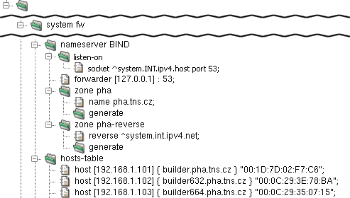
In the configuration depicted in Figure 5.20, “DNS Server - BIND configuration”,
the named daemon is configured in the
nameserver section to listen on the internal
address on port 53 (listen-sock ^system.INT.ipv4.host :
53) and to forward the request to dns-proxy
on the loopback interface (forwarder [127.0.0.1] : 53).
Finally, there is the zone pha section.
The name pha.tns.cz item assigns its name and
the generate item makes KGB generate the zone data from
hosts-table. The reverse item makes
zone pha-reverse provide reverse DNS records
for the local network.
The hosts-table section contains multiple
host items, each defining the host name (e.g.
"builder.pha.tns.cz") and the IP address (e.g.
"192.168.1.101") for a certain MAC address (e.g.
"00:1D:7D:02:F7:C6").
It is possible to globally force the clients to use SafeSearch
functionality for Google, YouTube and Bing by using
samples/include/safe-search.cml.
The Dynamic Host Configuration Protocol (DHCP) is used by a client to obtain information necessary to connect to an IP network automatically, with no need of manual administration. This information includes the client's IP address, network mask, default gateway, DNS server address, etc.
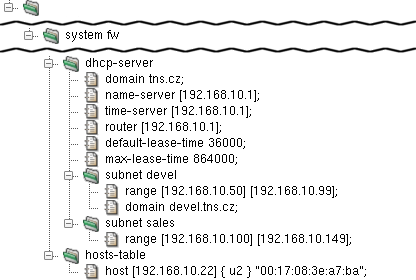
The DHCP server is configured in the dhcp-server
section. In this example, the DNS server address pushed by the DHCP server is
192.168.10.1 (name-server item). The lease time is set
to 10 hours (default-lease-time) and the maximum lease time
to 1 day (max-lease-time). Furthermore, there is a setting
for the domain name (domain), the router address
(router) and the NTP server (time-server).
There is a range of IP addresses (range [192.168.10.50]
[192.168.10.99]) reserved for subnet devel, which also
has the domain name altered to (domain devel.tns.cz). The
addresses assigned by DHCP server will therefore by between 192.168.10.50
and 192.168.10.99.
The hosts-table section defines a single host with a
predefined IP address: the host u2 with the MAC address
00:17:08:3e:a7:ba is assigned the IP address 192.168.10.22
(host [192.168.10.22] { u2 }
"00:17:08:3e:a7:ba").
See dhcp-server(5) for details.
It is very important to keep the correct time and date on all computer systems, including firewalls, internal servers, routers and even workstations. Kernun UTM provides a time synchronization function by means of an NTP server.
Kernun UTM's NTP server allows two functions: to synchronize the local time with a remote NTP server, and to serve this time data to the local systems. It uses the NTP protocol version 4, but retains compatibility with versions 3, 2 and 1 of the NTP protocol. It can play the client and server role at the same time. Thus, in a typical scenario, Kernun UTM's NTP server exchanges NTP messages with a few public time servers in order to keep its own time and date synchronized, while offering time synchronization to the whole local network.
Note
Local time zone of the Kernun UTM system is set in the console during the first boot, see Section 5.2, “Initial Configuration”.
From now on, we will assume that the initial configuration file is
loaded in the GUI, as shown in Section 2, “The Initial Configuration”. To define
NTP server parameters, we add a new ntp section at the
system level, for instance after the ssh-keys
section. As a minimum, we need to define one server in an item within
the ntp section, ns2.tns.cz
in our example. Furthermore, we want to let the internal systems synchronize their time
with Kernun UTM, which is achieved by adding an extra restrict
item. We use a reference ^system.INT.ipv4.net to specify our
local network; in more complex topologies, we would have to repeat the
restrict item and specify internal networks explicitly
or using variables. The nopeer and noquery
flags of the restrict item are used to allow only client
synchronization requests. Figure 5.22, “Minimum NTP server configuration” shows
the relevant part of configuration.
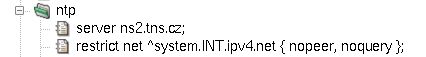
Reliance on a single external time server may lead to time synchronization outages.
Therefore, it is quite common to use more than one time server. The server
item can be repeated, which results in a stabler configuration.
Moreover, if there are more firewalls or parallel network servers, it is sometimes
beneficial to let them know about each other's NTP server, acting together as
peers. An NTP peer is not an authoritative source of time data, but may serve
for minor time corrections upon Internet blackouts. We achieve this effect
by specifying another NTP server with a peer item within
the ntp section, as shown in Figure 5.23, “Peer for NTP server”.
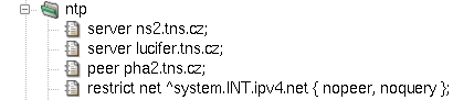
If the drift-file item is used, Kernun UTM's NTP server attempts
to compute the error in the intrinsic frequency of the local on-board clock.
The item must be accompanied with a filename, e.g. /var/ntp.drift.
The NTP server also includes support for local reference clocks,
if available.[27]
The on-board system clock itself may be used as a reference clock. An
example of its use is depicted in Figure 5.24, “On-board clock with NTP server”.
The clock item accepts three parameters:
Type—number 1 for local on-board clock.Unit—number 0 as the first (the only) unit of local on-board clock.Stratum—the distance in hops from an accurate authoritative time source; for the local on-board clock, we use number 10 to make it higher than standard Internet NTP servers.
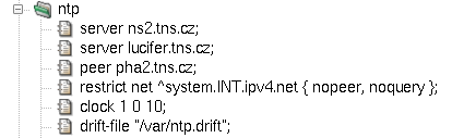
The resulting configuration file is available among Kernun UTM samples
under the name ntp.cml in
/usr/local/kernun/conf/samples/cml.
All Kernun UTM proxies write information about their state and progress into the log. The log can be
used later to analyze the traffic, generate statistics, find out why a certain connection was refused,
or look for system errors. Logging is switched on for all proxies by default. To
alter the log settings of a proxy, add a log section with desired items (see below) into it.
Logging can be done either by the standard syslog daemon (the default is the
LOCAL4 facility, which logs into the /var/log/kernun-debug file), or directly
into a specified file. Moreover, there is a possibility to log a small amount of the last data for each proxy into a
memory-mapped file, which can be used for system failure analysis. The facility item is used to
change the facility number, the file item to enable logging into a file and the mem-file
item to specify the memory-mapped file.
There are 9 levels of log messages (the lower the number, the higher the severity) and the administrator can choose
the level of logging. The log level of a proxy can be set either in the configuration using the
level item, or at runtime by sending a SIGUSR1/SIGUSR2 signal to
the proxy process to increase/decrease the level. The proxy logs only messages with a level lower or equal to its log level.
The log message level is appended to the MsgID column of the message, so you can easily filter only
messages of a certain log level in the log browser (Section 1.3, “Logs”).
Each log message contains the MsgID column, which stands for the type of the message. For every log message
type, there is a manual page in the section 6. The Message ID consists of a component code (an application name, possibly with
a suffix), message number and message log level.
Most of the information on normal traffic can be gathered from the level I (information statistical
messages) and level N (noticeable conditions), which are both logged with any log level set.
For example, a simple HTTP 1.1 request is started by TCPS-706-N which informs about a new TCP connection
and assigns the connection to a child, then a session is started (HTTP-710-I) and proceeds with the first
phase of acl. If the session is accepted, then the HTTP request is started (HTTH-702-I), request-acl is
evaluated (HTTH-811-I) and the client is connected to the server (MNIO-710-N). When
the answer, the document, arrives from the server, doc-acl is evaluated and the message HTTH-893-I is
added to the log. If the document was accepted, the request end message HTTH-713-I is added and the proxy
waits for other requests on the same socket (we are communicating over the multi-request HTTP 1.1 protocol). Then, possibly, more
requests are served and, eventually, the session is ended (HTTP-711-I), the proxy finishes the connection and
waits for a new one (messages TCPS-707-N and TCPS-715-N). The log of the described
situation is shown in Figure 5.25, “Log of an HTTP request”.
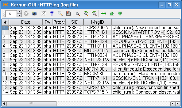
For more information on logging, see logging(7). For details concerning configuration of logging, see the log(5) manual page.
The created log files grow enormously and might fill all the free disk space. Another problem of logging is that
manipulation with big files is more difficult (and slower) than with smaller ones. Kernun UTM provides tools for
log rotation as a method of solving the above-mentioned problems. Log files are regularly (daily, weekly or monthly)
renamed and the system starts afresh with an empty log file. The old log files are thrown away after a certain period.
The administrator can configure log rotation by adding an rotate item into the system-level
rotate-log section for the entire Kernun UTM or into the log section of a particular proxy,
if it logs into a separate file. In the rotate item you can specify the owner, group and rights of the
file, the number of coexisting history logs, the compression method and the time of log creation. The logs can be
rotated either periodically (daily, weekly or monthly), or when the size of the log exceeds a specified limit.
The log rotation will only work if you have it scheduled in the crontab, as illustrated e.g. in
the sample crontab file /usr/local/kernun/conf/samples/include/crontab.cml.
Each of the connection-oriented proxies (http-, ftp-, imap4-, pop3-,
smtp-, sip-, sqlnet- and tcp-proxy) and udp-proxy are able to write
information about the current sessions (connections they are currently serving) into special binary files that can be
used to monitor their current state. A log does not provide all the necessary information when huge files are being downloaded:
we are informed that the request has started, but do not know anything until it ends. This is the right time to use the
monitor(1)
application, which collects information about the current session's progress and is able to present it to the user
(either as plain text, or in the HTML format). Monitoring is best accessible from the GKAT window of the Kernun GUI via
the Monitor tab in the detail of a proxy (or the Proxies root node). The information
in the monitor include the name and type of the proxy, the PID of the proxy process, the duration of the current session,
the server and client IP addresses and names, the number of bytes transferred and delivered in both directions, the connection
speeds, and the URI of the document (in the case of http- or ftp-proxy). Monitoring is only available for proxies that contain
the monitor section in their configuration.
Monitoring information is also stored in a database that is used for graph generation; for more details see Section 6.5, “Monitoring of System Parameters”.
Every proxy can generate statistics of its usage; these statistics are then shown in the statistics browser window (Figure 5.26, “Statistics browser window”), which is accessible via the menu in the GKAT. In the browser, the tree on the left-hand side shows the available statistics (for each of the available periods and all the proxies that generated statistics in that period). The right-hand part of the window shows the statistics of the selected period, date and proxy as an HTML page.
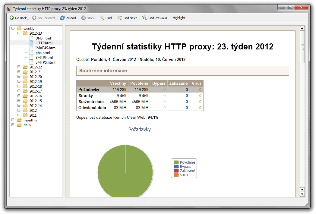
To enable the generation of statistics for the desired proxies or the whole system,
insert stats-daily, stats-weekly and/or stats-monthly
sections into their configurations. Inside these sections, you can specify the number of top results
for each watchable parameter (if not set, the default value will be used). By default, the generation
scripts for each of the periods are scheduled in the crontab. Therefore, no changes should be necessary.
Figure 5.27, “Configuration of statistics” shows a sample statistics configuration for an http-proxy.
Sample configuration with generation of statistics for most of the proxies and the whole system
is included in /usr/local/kernun/conf/samples/cml/statistics.cml.
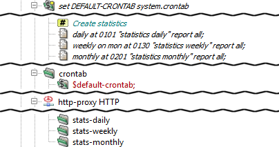
Kernun UTM is able to monitor various system parameters, from hardware temperature to
proxy loads, and store their values in a database. Later it is possible to create
and view graphs generated from these values and thus examine the traffic load history.
The graphs are generated by the command line tool rrd, described in the
rrd(1)
manual page, which can be also used to view the available graph types and intervals. The easiest way to
access the graphs is using the Graphs tab in the GKAT window of the Kernun GUI. It is available
for all the proxies and network interfaces, and for several system components. All the system parameters are
displayed in the Graphs tab of the top-level GKAT node, as depicted in Figure 3.8, “Graphs page”.
While system components other than proxies generate their graphs automatically, you have to insert
a monitoring section into the configuration of a proxy to generate its graphs.
Chosen graphs can be added to the Favorite graphs tab in the Graphs tab of
the top-level GKAT node to make them more accessible; the period of the displayed graphs can be changed using a combo box.
In general, a proxy can listen in two modes: non-transparent and transparent. In the non-transparent mode, the client must be aware of Kernun UTM, as it is connecting explicitly to some of its IP addresses. For example, the proxy address and port must be entered in the preferences dialog of the Web browser. According to the configuration of the protocol and of Kernun UTM, the proxy typically connects to a server and mediates the communication.
In the transparent mode, on the other hand, Kernun UTM captures clients' connections and hands them over to the proxies. Although the client thinks to be connected directly to the server IP address, it is in fact communicating with the proxy. Hence, the client does not have to be configured for using the proxy. The proxy typically creates the connection on its own and mediates the communication. According to the configuration, the proxy can either connect to a server (the one the client was connecting to, or even to another one), or it can react otherwise, e.g. deny the connection.
Incoming transparency (i.e., proxy listening in the
transparent mode) is configured by specifying the
transparent item in the
listen-on section in the proxy
configuration.
Let us demonstrate the transparency aspects on the example of
http-proxy. It is configured to listen in the
transparent mode on port 80 and in the
non-transparent mode on port 3128, as
depicted in Figure 5.28, “HTTP Proxy listening both in transparent and
non-transparent mode”.
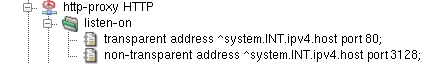
When one proxy listens in both modes simultaneously, clients can choose whether to connect in the transparent mode (by connecting directly to the Web server to its port 80), or non-transparently (by connecting to the proxy to port 3128). Examples of Web browser configuration dialogs are shown in Figure 5.29, “Configuration of non-transparent mode in Firefox and Microsoft Internet Explorer Web browsers”.
Figure 5.29. Configuration of non-transparent mode in Firefox and Microsoft Internet Explorer Web browsers
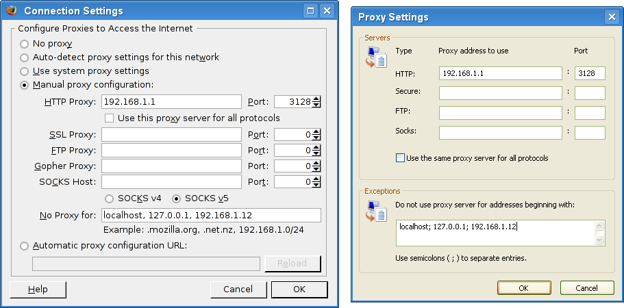
After the configuration is applied to Kernun UTM and
the proxy is restarted, it starts to listen on the two
given sockets. This can be verified in the
Network | sockstat tab of the GKAT
window, as depicted in
Figure 5.30, “Sockstat tab showing the list of all sockets
”. We can see
sockets listening for connection in the
transparent mode (rows marked ) and
in the non-transparent mode (rows marked
).
These sockets occur in the list more than once as they
are shared by the parent process and all the child
processes. The listening sockets show
*:* in the ForeignAddr column.
The non-transparent listening sockets show the
IP address they listen on in the
LocalAddr column.
The transparent listening sockets show the special symbol
>> in the
LocalAddr column, preceded by the
name of the interface, from which they accept connections.
In this example we can also see two clients to be actually
connecting through the proxy, both to the Web server at 194.228.50.79. Client from IP
192.168.1.31 is connecting
via the non-transparent proxy. We can see the
connection from the client to Kernun UTM's internal IP address
(row marked ), and the connection from
Kernun UTM's external IP address to the server (row marked
).
Client from the IP address 192.168.1.12 is
connecting transparently. We can see the connection
from the client to the server, which was
grabbed by Kernun UTM (row marked
)
and the connection from Kernun UTM to the server
(row marked
).
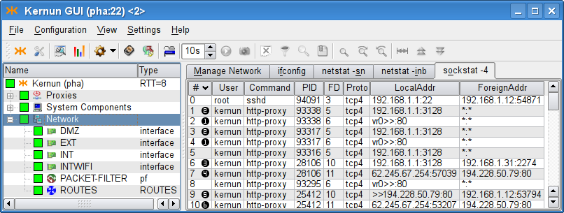
The realized connections can be traced in the log, as is shown in Figure 5.31, “Tracking transparent and non-transparent
connections in the http-proxy log
(the log was filtered, in order to save space).
”. We have filtered the log
messages that inform about the session—see the filters box in the
screenshot. The complete track of the session is more detailed,
concerning matching of ACLs, requests, documents, etc. The selected
message (HTTP-710-I) denotes the start of the
session in http-proxy,
and informs about the facts that are known at the time the session is
being established (client address, server address and the transparency
flag). The session end message (HTTP-711-I) would
also provide other informations concerning the session (the number of
requests, the length of the session, etc.).
Figure 5.31. Tracking transparent and non-transparent
connections in the http-proxy log
(the log was filtered, in order to save space).
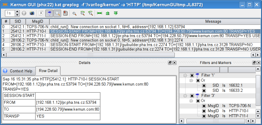
When a client is connecting to a server, the question is what IP address the server sees as the client IP address. Different approaches can be useful in different situations.
If a network with private addressing is hidden behind Kernun UTM, Kernun UTM must connect from its own (external, public) IP address. When the client network uses public IP addresses, both approaches can be desired: either the internal addressing should be hidden (the traffic should be formally realized from Kernun UTM's IP address), or not. On the other hand, a server protected in a DMZ may need to know the IP address of the real client.
By default, Kernun UTM proxy connects to the server from Kernun UTM's IP address (i.e. hiding the client's real IP address). However, there are two other options, which can be specified in the first-layer ACL (see Section 2.5, “Application Proxies and ACLs” for details on ACLs):
source-address clientdenotes that the IP address of the real client should be used as the source address;source-address forcedenotes that the givenaddressaddressshould be faked as the source address for the connection to the server.
The source-address item can be either specified
on the system level of the configuration, in which
case it influences all the proxies that reference the ACL, or
in the session-acl section of the particular proxy.
In Figure 5.32, “Transparency for servers (source-address client)
”, the real
client address is configured to be used as the source address for all
the named proxies, because it is specified in the system
ACL.
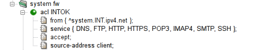
In Kernun UTM, a single port can be shared by several proxies or servers, provided that they do not collide in their listen sockets. For example, it is desirable to provide a transparent SSH proxy for connecting to SSH servers in the Internet and, at the same time, to provide an SSH server for administration of Kernun UTM. Both should be available from the protected network.
An example of such configuration is shown in Figure 5.33, “A port shared by two applications ”. When a packet arrives, Kernun UTM kernel delivers it to the most specific socket that is suitable for it. Consult transparency(7) for more information, including the definition of conflicting sockets and the socket preference. This way, it is possible to provide services on their traditional ports as well as transparent proxies on the same ports.
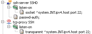
Kernun UTM proxy can be configured to listen on a set of contiguous
ports. This ability is also known as listening on a port
range and is available for TCP and UDP-based
proxies. If a transparent proxy listens on a port range (and
ACLs do not specify otherwise), the proxy connects to the
port the client was connecting to. If a non-transparent proxy
listens on a port range, the situation is similar to the regular
non-transparent proxy (one that listens on a single port): the
port (as well as the server IP address) would be either provided in
some ACL in the Kernun UTM configuration (for example, in the
plug-to item), or it is a part of the application
protocol. An example of sip-proxy configured
to listen on a port range is shown in the Figure 5.34, “The sip-proxy configured to listen transparently on a port range 5060-5062
”.
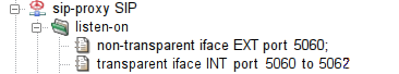
Warning
Proxies cannot listen on ranges of ports that collide with
the system default port ranges. The system normally assigns ports to connections
with unspecified source port from three port ranges, which can be
modified by the portrange-default,
portrange-high, portrange-low items in the
system.sysctl section. None of those ranges may overlap
with the range of ports that a proxy is listening on. In the case of a port range
collision, the system would not know, which ports are free to use and
which are occupied.
Note that this problem does not occur when the proxy listens on separate ports. In this case, the single ports are reserved for the use of the proxy (even if they are inside one of the system port ranges).
h323-proxy and gk-proxy
are the proxy daemons for a set of multimedia
communication protocols called H.323 protocols.
Kernun UTM supports them only for backward compatibility,
because this protocol family is now widely replaced by the SIP protocols
(see Figure 5.35, “SIP Proxy” below).
Therefore, this manual does not cover this topic.
For more information, see h323-proxy(8), h323-proxy(5), gk-proxy(8) and gk-proxy(5).
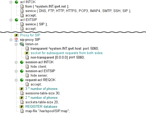
sip-proxy is the proxy daemon
for the Session Initiation Protocol (RFC 3261 et al.),
i.e. mainly Internet telephone calls and related services.
The proxy is configured in the sip section.
In the sample configuration depicted in Figure 5.35, “SIP Proxy”,
chroot-dir defines directory into which it should be chrooted.
The proxy listens transparently for requests at Kernun UTM's internal address
at port 5060. However, due to the hop-by-hop logic of the protocol,
the proxy must listen on this port non-transparently
on all internal and external interfaces as well.
As usually, the proxy must be referenced by at least one ACL in the
system section. In order to enable incoming calls,
we will need to allow also sessions from the external network.
sip-proxy uses two-phase ACLs. The first phase,
session-acl, is checked once for each client connection.
It permits or denies client access and sets some connection parameters.
This is where the administrator can specify that some important data
that is usually stored in SIP messages headers (e.g. internal addresses)
is to be hidden.
The second phase, request-acl, is checked once for
each request and it can be used e.g. to change the target server
according to the Request-URI.
sip-proxy requires specification of the maximum
of sessions and data channels used in parallel.
An estimate is three times number of the phones
for sessions-table-size
and two times number of the phones
for sockets-table-size.
Finally, the proxy requires a file to store the registration data
of clients (local phones).
The complete resulting configuration can be found
in /usr/local/kernun/conf/samples/cml/sip-proxy.cml.
See sip-proxy(8) and sip-proxy(5) to learn more about sip-proxy.
sqlnet-proxy is the proxy daemon
for the proprietary Oracle SQL*Net Protocol.
The proxy
can handle features, such as session redirection,
or database user checking.
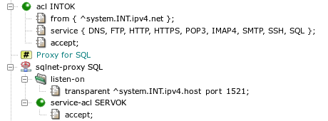
The proxy is configured in the sql section.
In the sample configuration depicted in Figure 5.36, “SQL*Net Proxy”
chroot-dir defines directory into which it should be chrooted.
The proxy listens transparently for requests at Kernun UTM's internal address
at port 1521.
As usually, the proxy must be referenced by at least one ACL in
system section.
The sqlnet-proxy uses two-phase ACLs. The first phase,
session-acl, is checked once for each client connection.
It permits or denies client access and sets some connection parameters.
The second phase, service-acl, is checked once for
each CN (connect) or RD (redirect) message and it can be used
e.g. to change the target server according to the SERVICE name.
The complete resulting configuration can be found
in /usr/local/kernun/conf/samples/cml/sqlnet-proxy.cml.
Since the protocol is proprietary, clients often violate it
and it is necessary to avoid some checks using configuration directives,
such as connect-string-charset.
See sqlnet-proxy(8) and sqlnet-proxy(5) to learn more about sqlnet-proxy.
Kernun UTM provides a generic proxy for handling application protocols based on UDP. Its philosophy is similar to the generic TCP proxy, which is used for the HTTPS and SSH protocols in the initial configuration, as described in Section 2.9, “HTTPS and SSH Proxy”. The proxy waits on one or more ports, transparently or non-transparently, for datagrams from clients. Although UDP is a stateless protocol, the UDP proxy defines logical sessions that group together related datagrams. See udp-proxy(8).
We will demonstrate the UDP proxy on the DNS protocol. It is one of typical applications of the UDP proxy[28]. Kernun UTM provides the DNS proxy (refer to Figure 4.11, “DNS Proxy”), which is a better choice for accessing DNS servers in the Internet, because it performs thorough checks of the protocol. However, if Kernun UTM connects two trusted internal networks and clients in one of them send DNS requests to a server in the other, the use of the UDP proxy may be sufficient.
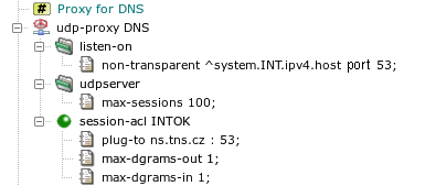
The DNS proxy in the sample configuration in Figure 5.37, “UDP proxy
” was replaced by the UDP proxy. It listens on the
internal network interface on the DNS UDP port 53 non-transparently. The item
max-sessions in section udpserver limits
the maximum number of logical sessions that can be handled by the proxy
simultaneously. All DNS requests from the internal network are accepted by
global acl INTOK. This ACL is extended in the proxy by
the plug-to item, which forwards all requests to a single DNS
server. As DNS is a request-reply protocol, we define that each logical
session contains at most one request (client to server) and one response
(server to client) datagram.
The setup described in this section can be tested by specifying in
plug-to a DNS server that accepts and recursively solves
requests from Kernun UTM. The client machines must be configured to use
Kernun UTM as their DNS server.
Web browsers support access to FTP servers by using URLs beginning with
ftp:. If no proxy is configured for FTP in the browser
parameters, the browser accesses FTP servers using the native FTP protocol.
Such communication can be mediated by a transparent FTP proxy. Another
situation is the non-transparent case, when a proxy for FTP is specified in
the browser settings. Then the browser communicates with the proxy using
the HTTP protocol, rather than FTP. Hence, the communication is processed by the HTTP
proxy, which gets a URL starting with ftp:. The proxy
must act as a FTP client, contact an FTP server, and send the result to the
browser via HTTP. The HTTP proxy does not support FTP directly. Instead,
it communicates with the FTP proxy using an internal
protocol[29]. The FTP proxy
handles the FTP part of the communication.
Both
http-proxy(8) and
ftp-proxy(8)
need to be reconfigured in order to cooperate
in the processing of ftp: requests from Web browsers. In the
ftp-proxy section, a new non-transparent
listening socket should be added to the listen-on section. The
two proxies run on the same system and they communicate via the loopback
interface. Hence, the socket for HTTP-FTP cooperation listens on the
localhost address and on an arbitrarily chosen port.
It is necessary to allow connections from the HTTP proxy
to the FTP proxy by adding a system-level acl and to tell the
FTP proxy in the corresponding session-acl that it should
expect requests from the HTTP proxy instead of the standard FTP. The HTTP
proxy must be told to pass FTP requests to the FTP proxy by adding a
ftp-proxy item to section http-proxy.
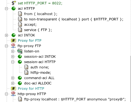
An example of FTP and HTTP configuration is shown in Figure 5.38, “Cooperation of HTTP and FTP”. Port 8022 has been chosen and stored in variable
HTFTP_PORT. A new acl HTFTP section has been
created, which permits connections in the FTP proxy from the local host to the
HTFTP port on the local host. In the ftp-proxy FTP
section, the FTP proxy is switched (by item htftp-mode) to
the HTFTP mode for connections accepted on the HTFTP socket. The HTTP proxy is
instructed how to contact the FTP proxy by item ftp-proxy.
The complete resulting configuration can be found in file
/usr/local/kernun/conf/samples/cml/htftp.cml. After
applying these configuration changes and restarting the HTTP and FTP proxies, it
should be possible to set the HTTP proxy as the proxy for FTP in the Web
browser and to start using ftp: URLs.
Kernun UTM supports network communication securing using the standard SSL
(Secure Sockets Layer) protocol and its newer version TLS (Transport Layer
Security). As the SSL/TLS protocol ensures end-to-end security, Kernun UTM
cannot read or modify data from an SSL/TLS connection between a client
and a server. This means that protocols using SSL/TLS encapsulation, e.g.,
HTTPS, POP3S, or IMAP4S, cannot be processed by a protocol-specific proxy.
Instead, generic TCP proxy is usually used to forward such communication. In
the case of HTTPS, a nontransparent HTTP proxy can be utilized for tunneling
HTTPS data in an HTTP connection with the CONNECT HTTP request
method. Sometimes, however, we need to have access to encrypted data for the
purposes of analysis or even modification. An example is antivirus checking of
files transferred via HTTPS.
The configuration described in this section is useful for fixed secure tunnels, e.g., via tcp-proxy, or for securing a single HTTP server by http-proxy. It is unsuitable for inspecting HTTPS traffic between ordinary HTTP clients (browsers) and servers, because the proxy presents a single server certificate (containing a single fixed host name) for any server accessed by a client. Common behavior of browsers is to compare the accessed server host name with the name in the server certificate and to issue a security warning if they do not match. If you need to handle this, HTTPS inspection, introduced in Section 19, “HTTPS Inspection”, is a viable option.
To access data protected by SSL/TLS, a proxy must split the communication into two SSL/TLS connections. Data from a client is first sent to the proxy via the first secure connection terminated on Kernun UTM. The encrypted data stream is decrypted by the proxy, processed, encrypted again and sent to the server via the second secure connection. Data from the server is passed via the two connections in the opposite direction. It is also possible to convert the unencrypted version of an application protocol (for example, HTTP) used by a client to the encrypted version (for example, HTTPS) accepted by a server, or vice versa.
An example of a proxy that uses SSL/TLS security is presented in Section 14.7, “HTTP Authentication Proxy”, and its configuration is shown in Figure 5.51, “Configuration of the HTTP authentication proxy”. This proxy converts a secured connection from a client to plain HTTP sent to the server. Another example is depicted in Figure 5.39, “SSL/TLS security configuration”. It is an HTTP proxy that enforces authentication of the remote server and also authenticates Kernun UTM to the remote server.
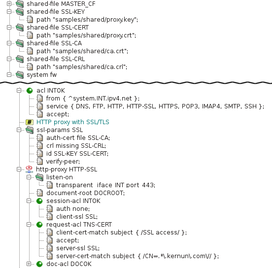
The parameters of an SSL/TLS connection are defined by the section
ssl-params . All the available parameters are explained in
ssl(5). In our example, this section selects
the X.509 certificate with the related private key used by the proxy to
authenticate itself to clients and servers (item id),
and the list of certification authority certificates
(auth-cert) with the related certificate revocation lists
(crl) for verification of certificates provided by peer
clients and servers. The verify-peer item forces the proxy to
request and verify certificates of peers. If a peer does not provide
a certificate or the certificate cannot be verified, the SSL/TLS handshake
fails and the session is terminated.
The client-ssl SSL item in the
session-acl INTOK section switches the connection from the
client to the SSL/TLS mode and sets the protocol parameters. If the client
establishes an encrypted connection and sends a valid certificate, it can
send an HTTP request. Otherwise, the session is terminated. After receiving
an HTTP request, the proxy searches for a request ACL. It selects
request-acl TNS-CERT only if the client's certificate
contains “SSL access” in the subject
field, because of the client-cert-match item. The request ACL
enables SSL/TLS on the connection to the server and sets the protocol parameters.
The server-cert-match item defines conditions that must be
fulfilled by the server's certificate (it must contain a common name ending by
“kernun.com” in our example). Note that
if the client-cert-match item is not matched, the single ACL
is skipped and the search continues at the next request ACL, whereas if the
server-cert-match item is not matched, the request is terminated
immediately.
If you apply this kind of configuration and access a Web server via the proxy, your Web browser will show that the peer certificate is that of the proxy. In the proxy log, you will see details of the client's and server's certificates as received by the proxy.
Kernun UTM applies different rules to network traffic depending on the identity of the communicating parties. A client or a server can be identified in several ways. The basic one is the IP address and the port number, which are available for any network connection. The IP-based identity is used very often, but it distinguishes between computers, not users. Sometimes it is necessary to apply different rules to different users, while each user can work on several machines and each machine can be utilized by more than one user. In such situations, we need to identify individual users, independently on the IP addresses of the computers they use. Kernun UTM provides various means of user authentication. An authenticated user name can be used as one of the conditions tested when searching for an applicable ACL.
Some application protocols allow the passing of user credentials to a proxy within the normal protocol data flow. In Kernun UTM, such type of authentication is supported by the HTTP and FTP proxies. Many other proxies are able to use out-of-band (OOB) authentication, which binds a user name to a client machine IP address. Kernun UTM also provides a special authentication mode usable for protecting access to protected HTTP servers from clients in the external network—the HTTP authentication proxy.
Examples of configuration for all variants of authentication except NTLM
described
in this section are summarized in the sample configuration file
/usr/local/kernun/conf/samples/cml/auth.cml.
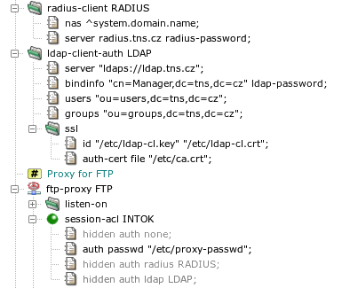
Kernun UTM supports several methods, described in detail in
auth(7). Section
ftp-proxy FTP in Figure 5.40, “Authentication methods”
contains sample auth items for different authentication
methods. To switch to another authentication method, simply hide
the single not hidden auth item and unhide another one.
- None
No user authentication is performed.
- Password file
The user provides a user name and a password, which are compared to name-password pairs in a password file stored locally on Kernun UTM. The administrator must create—by utility fwpasswd(1)—a file containing valid user names with encrypted passwords (
/etc/proxy-passwdin the example configuration).- RADIUS
The user name and password are verified by a RADIUS server. There are two variants: name/password (the user enters his name and the password) and challenge/response (the user enters her name, the RADIUS server generates a challenge, and the user replies by a response derived from the challenge and some secret information, e.g., using an authentication token hardware). If the
radiusmethod is chosen in anauthitem, it must reference aradius-clientsection that defines the parameters needed to connect to a RADIUS server.- LDAP
The user name and password are verified in an LDAP database. If the
ldapmethod is chosen in anauthitem, it must reference anldap-client-authsection that defines the parameters needed to connect to an LDAP server. If a secure connection to the LDAP server is used (the LDAP server URI begins withldaps), the certificates to be used must be specified in theldap-client-auth.sslsubsection.- Kerberos
The Kerberos authentication is specific to the http-proxy. If a user is authenticated in an Active Directory domain (or has a Kerberos TGT), a Web browser uses the user's Kerberos tickets and does not require any interaction with the user (name and password entry).
- NTLM
The NTLM authentication is specific to the http-proxy and HTTP clients (Web browsers) running on Microsoft Windows client operating systems. If a user is authenticated in an Active Directory domain, a Web browser uses the user's credentials known by the system since the login time and does not require any interaction with the user (name and password entry). It can be combined with other authentication methods for clients that do not support NTLM.
Note
If a proxy runs in chroot, the paths in
auth passwd and ldap-client-auth.ssl
are interpreted in the context of the chroot directory.
User authentication in the FTP proxy can be enabled using the
auth item that specifies an authentication method other than
none in session-acl. For example, a
proxy with the configuration shown in Section 14.1, “Authentication Methods” will
use a local password file. If authentication is enabled and the user does
not provide valid credentials, the proxy terminates the session.
Otherwise, it is possible to match user name or group using a
user item of command-acl. There are several
ways of sending authentication data to the proxy, see
ftp-proxy(8). An example FTP session initiation
with authentication, using a command line FTP client:
$ftp fw.pha.tns.czConnected to ftp.tns.cz. 220-fw.pha.tns.cz KERNUN FTP Proxy (Version KERNUN-3_0-RELEASE) Ready. Target server name/address and authentication to proxy required. You can use loginname in form of proxy_user@server_user@server. 220 Log in with USER and PASS command.Name (192.168.10.1:user):guest@anonymous@ftp.tns.cz331-USER command successful. Proxy user: 'guest'. Target-server user: 'anonymous'. Target server: ftp.tns.cz, port: 21. Enter password in form proxy_user_password@server_user_password. 331 Enter password or response, please.Password:****@****230-User 'guest' succesfully authenticated. 230-pha.tns.cz KERNUN FTP Proxy (Version KERNUN-3_0-RELEASE) Ready. 230-Welcome to ftp.tns.cz FTP service. 230----- proxy connected to [194.228.50.76]/ftp.tns.cz port 21 ---- ---- proxy connected to ftp.tns.cz port 21 ---- 230-Please specify the password. 230 Login successful. Remote system type is UNIX. Using binary mode to transfer files.ftp>
A similar, but unsuccessful session initiation (due to a wrong password):
$ftp fw.pha.tns.czConnected to ftp.tns.cz. 220-fw.pha.tns.cz KERNUN FTP Proxy (Version KERNUN-3_0-RELEASE) Ready. Target server name/address and authentication to proxy required. You can use loginname in form of proxy_user@server_user@server. 220 Log in with USER and PASS command.Name (192.168.10.1:user):guest@anonymous@ftp.tns.cz331-USER command successful. Proxy user: 'guest'. Target-server user: 'anonymous'. Target server: ftp.tns.cz, port: 21. Enter password in form proxy_user_password@server_user_password. 331 Enter password or response, please.Password:****@****421 User 'guest' not authenticated. ftp: Login failed.ftp>
Selected log messages related to these two FTP sessions are displayed in Figure 5.41, “Log of authentication in FTP proxy”.
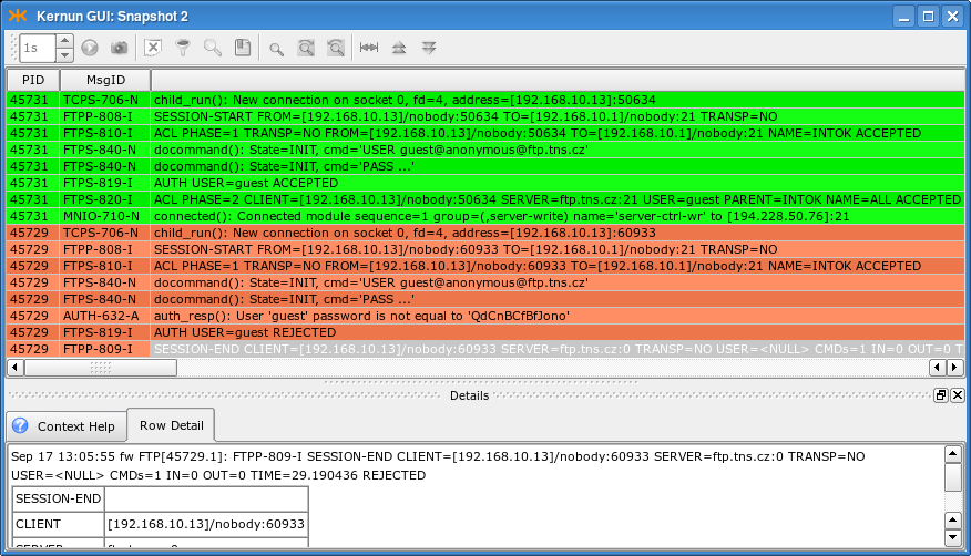
The HTTP proxy supports proxy authentication using the Basic authentication method, i.e., a name and a password entered by the user. The technical details of the authentication are described in http-proxy(8). Proxy authentication in HTTP works as follows: the first request sent by the client (browser) is unauthenticated, the proxy replies with response code 407 “Proxy Authentication Required”; upon reception of this response code, the browser displays a dialog (see Figure 5.42, “Proxy authentication dialog in a Web browser”) asking for user credentials; the browser then repeats the request with the user name and password attached.
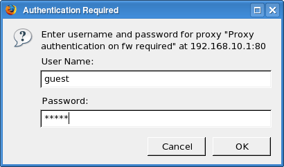
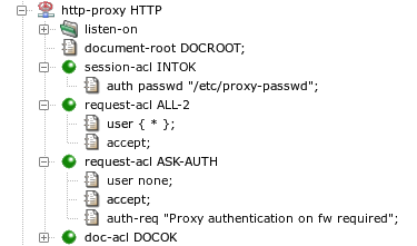
Figure 5.43, “User authentication configuration in the HTTP proxy” contains an HTTP proxy
configuration with user authentication. The authentication is enabled and
the authentication method (a password file in this case) is selected by the
auth item in session-acl. If a request
contains user credentials, they are checked and if correct, the
user name—and the list of groups the user belongs to—is
remembered for matching with the user item in a
request-acl. Unlike in the case of FTP proxy, a request
containing invalid or no credentials is not rejected. The processing
continues, but no request-acl containing a
user item matches, except for the one with
user none. There should be a
request-acl that matches unauthenticated requests and
returns the 407 response. In the example configuration, there are two
request-acl sections. The first one,
request-acl ALL-2, matches any successfully
authenticated user. The request is processed normally, i.e., forwarded to
the target server. The other, request-acl ASK-AUTH,
matches if the request does not contain valid user credentials[30]. The 407 response is
forced by the auth-req item. This item also sets the
realm (prompt) that is usually displayed by the
browser in the authentication dialog, as depicted in Figure 5.42, “Proxy authentication dialog in a Web browser”.
If we apply this sample configuration to Kernun UTM and invoke
a new request in a Web browser, the log will contain messages similar to
those in Figure 5.44, “Log of user authentication in the HTTP proxy”. The first request was
unauthenticated. The two orange messages inform us that
request-acl ASK-AUTH was selected and response 407
was returned to the browser. After the user filled in the authentication
dialog, the request was repeated. The user name and password were correct,
user guest was authenticated
successfully, and request-acl ALL-2 was selected,
as indicated by the two green messages.
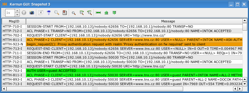
Important
Because many Web browsers do not expect to be required to perform proxy authentication when no HTTP proxy is configured in the browser, proxy authentication may not work with a transparent proxy. It is possible in such a case that users are displayed a 407 error page instead of the authentication dialog. Use proxy user authentication with a non-transparent HTTP proxy only, unless you check that Web browsers on your client machines handle it correctly with a transparent HTTP proxy.
The Kerberos authentication is an alternative to the Basic authentication described in Section 14.3, “Basic Authentication in HTTP Proxy”. It provides a single-sign-on capability for clients authenticated in an Active Directory domain or a Kerberos realm. If a user is logged in a domain, or has a valid Kerberos ticket, a Kerberos-capable Web browser can authenticate the user to the proxy automatically, without asking the user for a name and a password.
Kerberos authentication in Active Directory is supported for Microsoft Windows server and Samba 4 acting as an Active Directory domain controller. Older Samba versions (3.x) cannot be configured as an AD domain controller.
Warning
Authentication to a Samba server uses different
authentication mechanism than a MS Windows Server by default. This
authentication mechanism (GSS-SPNEGO) fails and may allocate all available
memory. Hence, the client (Kernun http-proxy) should be
configured to use GSSAPI instead. This can be done by adding file
.ldaprc to the root directory and to home directories
of users involved in authentication (root and kernun). The file should contain line:
SASL_MECH GSSAPI
Important
If an HTTP proxy uses the Kerberos authentication, it cannot be run chrooted, because it needs access to some system components that are not contained in the standard Kernun chroot environment.
An example of a Kerberos configuration is stored in the sample
configuration file
/usr/local/kernun/conf/samples/cml/kerberos-auth.cml.
The system section contains global configuration related
to the Kerberos authentication in section kerberos-auth,
Figure 5.45, “Kerberos authentication — section
system”. Two parameters are required:
the name of the Active Directory domain (or Kerberos realm)
domain and the address of the domain controller (or the
Kerberos KDC) ad-controller. The Kerberos authentication
itself provides the name of an authenticated user to the proxy.
A request-acl can be selected according to the user name
or group membership. For the latter option, the proxy needs to know the
list of groups the user belongs to. The list can be obtained from an LDAP
server. As the Active Directory contains all the necessary information and
provides LDAP interface, the Active Directory controller is usually used
as the LDAP server. Obtaining group membership can be configured by
unhiding the hidden item ldap and section
ldap-client-auth in the sample configuration in Figure 5.45, “Kerberos authentication — section
system”. The URL of the LDAP server references
the Active Directory controller. The proxy authenticates itself to the
LDAP server by Kerberos using the machine account of the Kernun system in
the Active Directory. The Kerberos authentication for LDAP is enabled by
ldap-client-auth.kerberos. Alternatively, the proxy can
authenticate itself using a name and a password of a user with the
permission to access the Active Directory contents for reading. The user's
credentials must be specified in the bindinfo item in
place of ADUserldap-passwordactive-directory, which also specifies the domain name.
Important
The Active Directory domain name must be written using UPPERCASE LETTERS in the configuration.
Warning
A user's primary group name (usually Domain Users) is neither logged nor
matched by request-acl.user.group.
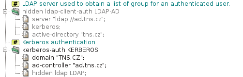
The Kerberos configuration can be enabled in an HTTP proxy by item
session-acl.kerberos-auth. Outcome of the Kerberos
authentication is processed like the Basic authentication. The user name,
optional list of groups, or the fact that the authentication failed, can
be used as conditions in request-acl sections. There is
usually one or more request ACLs that permit access to successfully
authenticated users and one request ACL that denies access to
unauthenticated users and asks for authentication. The sample
configuration in Figure 5.46, “Kerberos authentication — section
http-proxy” allows
access to any authenticated user
(request-acl AUTH-OK). Users that are not
authenticated are requested to perform authentication by
request-acl AUTH-REQ.
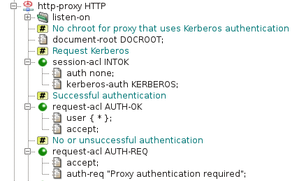
In the Kerberos and LDAP configurations presented so far, user and
group names are matched in ACLs and written to logs in a short form,
without information about domains they belongs to. This may not be
sufficient in a multi-domain environment, where different domains may
contain users and groups with the same names. Such a multi-domain
environment can comprise either domains in a single Active Directory
forest, or even domains from several forests if there are explicit trusts
between forests[31]. Configuration item
kerberos-auth.user-match full switches to using long
user name in logs and ACLs in format
“user@REALM” instead of the default short
format “user”. Likewise, adding value
“group-match domain” to item
ldap-client-auth.active-directory enables using long
group names “group@domain”.
The LDAP server on each Active Directory controller returns only
data from its own domain. Hence, group membership of a user must be
queried in the domain which the user belongs to. The proxy is able to
select the LDAP server according to the domain name of the authenticated
user. To do this, there must be an ldap-client-auth
section for each domain. Section kerberos-auth must
contain item ldap domain, instead of naming a single
ldap-client-auth section. Then the
ldap-client-auth section will be selected by its Active
Directory domain name (specified in item
active-directory).
Information about membership of Kerberos-authenticated users in
groups can be cached in order to decrease load of LDAP servers.
Configuration of caching consists of adding the global section
oob-auth OOB and referencing it by item
http-proxy.oob-auth-srv. Cached group membership
information for a user name expires after a timeout controlled by items
kerberos-auth.timeout-idle (expiration after a period of
inactivity) and kerberos-auth.timeout-unauth
(unconditional expiration).
The Kerberos authentication requires some initialization steps before in order to start working. There are two supported methods of initialization.
Important
In order to work correctly, Kerberos authentication requires several conditions to be fulfilled:
The Kernun system and the Active Directory domain controller must have their system time synchronized. By default, maximum allowable clock difference is 5 min. It is possible to synchronize Kernun system's clock to the Active Directory time by configuring the domain controller as an NTP server in the Kernun configuration.
The Kernun system must resolve the domain name of the Active Directory domain controller to the correct IP address. The reverse resolution of this IP address must also work and yield the original domain name used for the forward resolution as the first name of the response.
The first method adds the Kernun system to the Active Directory
domain by deleting its machine account if it already exists and creating
a new machine account. Then it sets up the Kerberos keytab with all keys
necessary for authentication and obtaining group membership information.
A user account userDomain Admins rights is required for
this task. The initialization process is performed by issuing shell
commands on the Kernun system:
#kinituser#ldapdelete -v -H ldap://ADCcn=COMPUTER,cn=Computers,dc=D1,dc=D2...#msktutil -c --computer-name `hostname -s` -s HTTP/`hostname` \ -h `hostname` --serverADC--no-pac#chown kernun /etc/krb5.keytab
where ADCD1, D2, ...example.com, we use
dc=example,dc=com). The computer account name COMPUTER--computer-name with appended character
'$'. If the default computer account name
`hostname -s` is used, a command for automatic
password renewal (msktutil --auto-update) will be
added to /etc/crontab. It is possible to choose
another computer account name. A non-default name must be configured in
the http-proxy by setting
kerberos-auth.kinit to
". In this case,
the machine account password renewal must be handled manually, or (better)
password expiration must be turned off for the account by option
computername$"--dont-expire-password of msktutil.
Important
The computer account name must be entered to the
configuration with the appended character '$'.
Example: The initialization commands will be, for the domain
administrator admin, the Active
Directory domain EXAMPLE.COM,
the domain controller ad.example.com, and the Kernun system
kernun.example.com:
#kinit admin#ldapdelete -v -H ldap://ad.example.com \ 'cn=kernun$,cn=Computers,dc=example,dc=com'#msktutil -c --computer-name `hostname -s` -s HTTP/`hostname` \ -h `hostname` --server ad.example.com --no-pac#chown kernun /etc/krb5.keytab
If clients should access the proxy via a name different from the
fully qualified host name of the Kernun system, that name must be
specified in the -s argument of the
msktutil command. The same name must be configured in
kerberos-auth.proxy-host or
session-acl.kerberos-auth.
Instead of saving the created keytab into the default location
/etc/krb5.keytab, another file name can by set by
adding option
-k to the
msktutil command line. The custom keytab location must
be configured as a keytab_fileshared-file referenced from
kerberos-auth.keytab.
If the system is to be removed from the domain later (when Kerberos
authentication is no more required or if the system will be moved to
another domain), remove file /etc/krb5.keytab and
delete the machine account on the Active Directory Controller.
The second method of Kerberos initialization comprises generating a keytab on the Active Directory controller, transferring the keytab to the Kernun system, and configuring Kernun to use the keytab. The initialization procedure consists of several steps:
Create a user account in the Active Directory. The account must be configured so that its password never expires and it must have enough rigths to read user and group information from the Active Directory (usually, membership in the
Domain Usersgroup suffices).Generate the keytab using the command line on the domain controller:
C:\>ktpass /outKEYTAB/princ HTTP/PROXY@AD_DOMAIN/mapuserUSER@AD_DOMAIN/pass * /crypto All /ptype KRB5_NT_PRINCIPALwhere the parameters are:
KEYTABThe file name for the created keytab file.
PROXYThe proxy name used by clients. If it it not the fully qualified host name of the Kernun system, the name must be configured in
kerberos-auth.proxy-hostorsession-acl.kerberos-auth.AD_DOMAINThe Active Directory domain name, in upper case.
USERThe name of the user created in step 1. The command will request entering this user's password. Alternatively, the password may be specified on the command line by
/passinstead ofPASSWD/para *.
Copy the keytab to the Kernun system or to the computer running Kernun GUI.
Configure the keytab as a
shared-fileand add a reference to this shared file intokerberos-auth.keytab. The keytab shared-file should be stored in a location included in backup and upgrade, for example,/usr/local/kernun/conf.Set
kerberos-auth.kinitto the proxy principal nameHTTP/.PROXY
Example: The keytab creation command will be, for the Kernun user
account kernun, the Active
Directory domain EXAMPLE.COM,
the Kernun system kernun.example.com, and the output keytab
file krb5.keytab:
C:\>ktpass /out krb5.keytab /princ HTTP/kernun.example.com@EXAMPLE.COM /mapuser kernun@EXAMPLE.COM /pass * /crypto All /ptype KRB5_NT_PRINCIPAL
Note
Configuring a keytab as a shared file makes easy distribution of the keytab to cluster nodes.
If Kerberos authentication is no more required, remove the keytab from the Kernun system and delete the user account from the Active Directory controller.
As was already mentioned, web browsers usually refuse proxy authentication on a transparent HTTP proxy. This problem can be solved by redirecting an unauthenticated transparent HTTP request to an authentication server. The server performs authentication, remembers the association of an IP address to a user name in the out-of-band authentication table, and redirects the request back to the origin server. As the Kerberos authentication is done in the background, it is invisible to the user.
An example of a Kerberos transparent proxy configuration is stored in
the sample configuration file
/usr/local/kernun/conf/samples/cml/kerberos-auth-transp.cml.
The proxy must be configured as an OOB authentication server by
adding the oob-auth global configuration section and
referencing it by item http-proxy.oob-auth-srv. Kerberos
and optional LDAP configuration is like in the non-transparent case, see
Figure 5.45, “Kerberos authentication — section
system”.
The HTTP proxy configuration is shown in Figure 5.47, “Transparent Kerberos authentication — session ACLs” and Figure 5.48, “Transparent Kerberos authentication — request ACLs”. Global
acl INTOK-AUTH and the corresponding
session-acl INTOK-AUTH handle transparent requests to
origin servers. These requests are authenticated using out-of-band
authentication. Authenticated users are passed by
request-acl HTTP-OK. If a user is not authenticated,
the request will be redirected to the authentication server by
request-acl HTTP-RDR. Redirected requests are handled
by global acl HTTP-AUTH and the corresponding
session-acl HTTP-AUTH. The client is asked for
Kerberos authentication by request-acl AUTH-REQ.
Authentication is performed by the browser without asking the user for
a name or a password. Then request-acl AUTH-OK stores
the IP address of the successfully authenticated user into the out-of-band
table and redirects the browser to the originally requested URI. Further
requests use OOB authentication and are handled without redirection to the
authentication server.
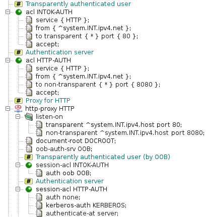
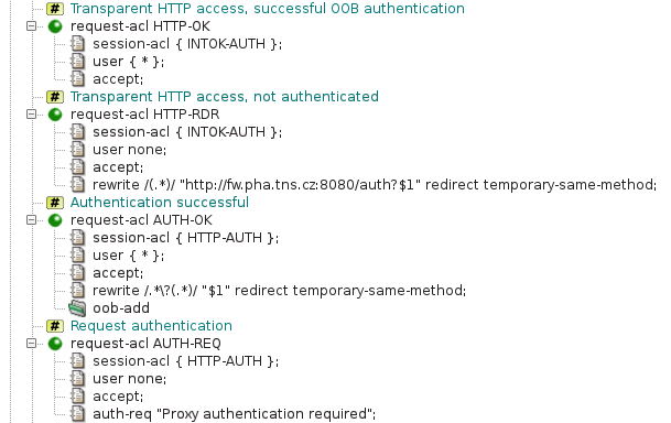
Important
In Firefox, Kerberos authentication must be explicitly
enabled for each server, in our example fw.pha.tns.cz. It can be done by typing
a special uri about:config into the address line to show
advanced settings, and then setting the server name to option
network.negotiate-auth.trusted-uris.
Important
Internet Explorer, Chrome and Opera users may be prompted for a password to authenticate to the authentication server. To avoid it they must configure the browser for automatic logon. To do this
Go to the
Internet Optionsdialog box, on theSecuritytab selectLocal intranet, and then clickCustom Level.In the
Security Settingsdialog box, underLogon, selectAutomatic logononly inIntranet zone, and then clickOK.In the
Internet Optionsdialog box on theSecurity Settingstab withLocal intranetstill selected, clickSites.In the
Local intranetdialog box, clickAdvanced.In the next dialog box (also titled
Local intranet), type the URL of the authentication server http://fw.pha.tns.cz:8080/ in theAdd this Web site to the zone box, and then clickAdd.
The NTLM authentication is an alternative to the Basic authentication described in Section 14.3, “Basic Authentication in HTTP Proxy”. It provides a single-sign-on capability for Microsoft Windows clients authenticated in an Active Directory domain. If a user is logged in a domain, an NTLM-capable Web browser can authenticate the user to the proxy automatically, without asking the user for a name and a password. The NTLM authentication can be used instead of the Basic authentication, or both authentication methods can be used together. In an NTLM-only configuration, clients incapable of the NTLM authentication cannot authenticate. In a configuration with both authentication methods, an NTLM-capable client uses NTLM and other clients use Basic.
Important
If an HTTP proxy uses the NTLM authentication, it cannot be run chrooted, because it needs access to some system components that are not contained in the standard Kernun chroot environment.
Important
The DNS domain name of the Active Directory controller
must correspond to the Active Directory domain name. For example, a domain
controller for the domain tns.cz
should be named like ad.tns.cz.
An example of an NTLM configuration is stored in the sample
configuration file
/usr/local/kernun/conf/samples/cml/ntlm-auth.cml.
The system section contains global configuration related to
the NTLM authentication in section ntlm-auth, see Figure 5.49, “NTLM authentication — section
system”. Two
parameters are required: the name of the Active Directory domain
(domain) and the address of the domain controller
(ad-controller). The NTLM authentication itself provides
the name of an authenticated user to the proxy.
A request-acl can be selected according to the user name
or group membership. For the latter option, the proxy needs to know the
list of groups the user belongs to. The list can be obtained from an LDAP
server. As the Active Directory contains all the necessary information and
provides LDAP interface, the Active Directory controller is usually used
as the LDAP server. Obtaining group membership can be configured by
unhiding the hidden item ldap and section
ldap-client-auth in the sample configuration in Figure 5.49, “NTLM authentication — section
system”. The URL of the LDAP server references
the Active Directory controller. A user with the permission to access the
Active Directory contents for reading must be specified in the
bindinfo item in place of ADUserldap-passwordactive-directory, which also specifies the domain name.
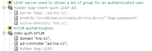
The NTLM configuration can be enabled in an HTTP proxy by item
session-acl.ntlm-auth. Outcome of the NTLM authentication
is processed like the Basic authentication. The user name, optional list
of groups, or the fact that the authentication failed, can be used as
conditions in request-acl sections. There is usually one
or more request ACLs that permit access to successfully authenticated
users and one request ACL that denies access to unauthenticated users and
asks for authentication. The sample configuration in Figure 5.50, “NTLM authentication — section
http-proxy” allows access to any authenticated
user (request-acl AUTH-OK). Users that are not
authenticated are requested to perform authentication by
request-acl AUTH-REQ.
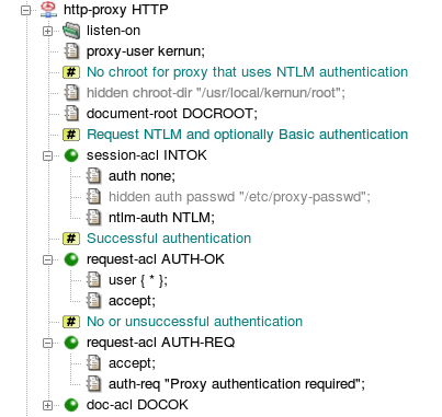
Administrators often want to enable the more user-friendly NTLM
authentication and to provide an alternative for clients that are not
capable of the NTLM authentication. Such a configuration can be created by
setting both items ntlm-auth and
auth in the same session-acl, for
example, by unhiding the line
“hidden auth passwd ...” in
Figure 5.50, “NTLM authentication — section
http-proxy”. The proxy will offer both NTLM
and Basic authentication schemes. The client can choose any of
them[32].
After the NTLM authentication is configured and the configuration
applied to a Kernun system, it is necessary to add the Kernun system to
the Active Directory domain. A user account
userDomain Admins rights is
required for this task. The Kernun system is added to the domain by the
shell command
#net ads join -Uuser
The system should then be rebooted in order to initialize and start the system components that provide an interface between the proxy and the Active Directory controller[33]. If the NTLM authentication is no more required, or if the Active Directory domain or the domain controller changes, the system should be removed from the domain by the shell command
#net ads leave -Uuser
It can be later added to another domain by
net ads join.
Membership of a Kernun system in an Active Directory domain can be tested
by the shell command wbinfo -t. If the system
has been successfully added to a domain, we get:
#wbinfo -t; echo $?checking the trust secret via RPC calls succeeded 0
Otherwise, the output is:
#wbinfo -t; echo $?checking the trust secret via RPC calls failed error code was NT_STATUS_NO_TRUST_SAM_ACCOUNT (0xc000018b) Could not check secret 1
Results of NTLM authentication can be cached by out-of-band authentication (see also Section 14.8, “Out of Band Authentication”), in order to decrease load of Active Directory and LDAP servers. Each new client is authenticated by NTLM. The combination of the client IP address, the user name and the list of groups is remembered in the OOB session table. Following requests from the same IP address will be authenticated as the same user and groups, without contacting the AD controller and the LDAP server. Computer accounts (i.e. users whose name ends with a dollar) are not added to the OOB session table.
Configuration of NTLM caching consists of adding the global section
oob-auth OOB, referencing it by item
http-proxy.oob-auth-srv, and adding item
auth oob OOB to each
session-acl that contains item
ntlm-auth. Cached user and group information for a client
IP address expires after a timeout controlled by items
ntlm-auth.timeout-idle (expiration after a period of
inactivity) and ntlm-auth.timeout-unauth (unconditional
expiration).
Tip
The preferred authentication method in Active Directory environment is Kerberos, see Section 14.4, “Kerberos Authentication in HTTP Proxy”.
The HTTP proxy can be used to control access to a Web server in the protected network[34] from clients in the external network. A typical situation is a Web interface to a corporate mail server accessed by employees from machines in the Internet, for example from their homes. In such a case, the security policy often requires the use of sessions with limited lifetime authenticated by a strong mechanism, such as a challenge-response protocol that utilizes one-time passwords generated by hardware authentication tokens. Also, as we mentioned in Section 14.3, “Basic Authentication in HTTP Proxy”, HTTP proxy authentication does not often work if the proxy is not configured in the browser explicitly. For such situations, there is a special operation mode of the HTTP proxy, called the HTTP authentication proxy, or AProxy for short.
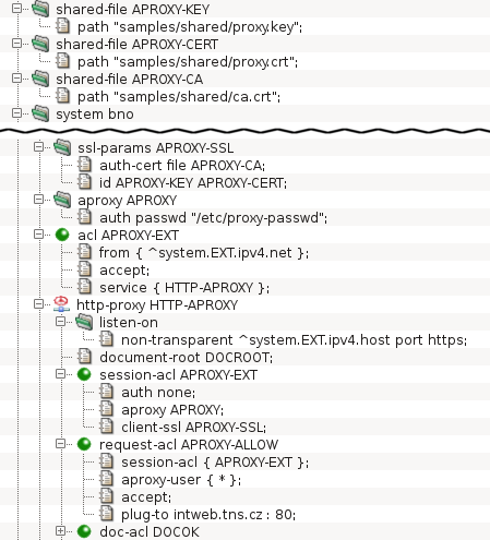
A typical AProxy configuration is displayed in Figure 5.51, “Configuration of the HTTP authentication proxy”. It is a configuration for access from
clients in the Internet to the server intweb.tns.cz in the internal
network. As the Internet is an untrusted network, the connections from
clients are secured by TLS, which is enabled by the
ssl-params APROXY-SSL section and the
client-ssl
item in session-acl APROXY-EXT. The internal network is
considered secure, therefore plain unencrypted HTTP is used. (For
detailed explanation of SSL/TLS in Kernun UTM, see Section 13, “Secure Communication Using SSL/TLS”.)
The configuration section aproxy APROXY defines
various parameters of the AProxy. The example contains only the
auth item, which defines that the AProxy will verify user
credentials against a local password file. The default maximum session
time after a successful authentication is one hour. After that time, the
user is logged out and must authenticate again. Also, if the session is
idle—the client does not issue any request—for more than
5 minutes, the user must reauthenticate. These default timeout values
can be changed by items timeout-unauth and
timeout-idle of section aproxy.
Further configurable AProxy parameters are described in
http-proxy(5).
The AProxy mode is activated by the aproxy item of
a session-acl. The user name obtained during AProxy
authentication can be used to select a request-acl, by
matching an aproxy-user item. In the sample
configuration, a client accesses the AProxy by connecting to the
external IP address of Kernun UTM. If authentication succeeds, the HTTP
requests from the client are passed to the internal server defined by
plug-to.
Warning
An AProxy session cookie is a sensitive piece of
information and should be kept secret, because an attacker could use it to
steal the identity of an authenticated user. Hence, the AProxy is usually
configured so that the connections between clients and the proxy are
secured by SSL/TLS (see Section 13, “Secure Communication Using SSL/TLS”). It is possible to
operate the AProxy using plain HTTP by enabling
aproxy.insecure-cookies and not configuring
client-ssl on the client side of the proxy, but it is
strongly recommended not to so unless the clients are connected
to Kernun UTM via a trusted network.
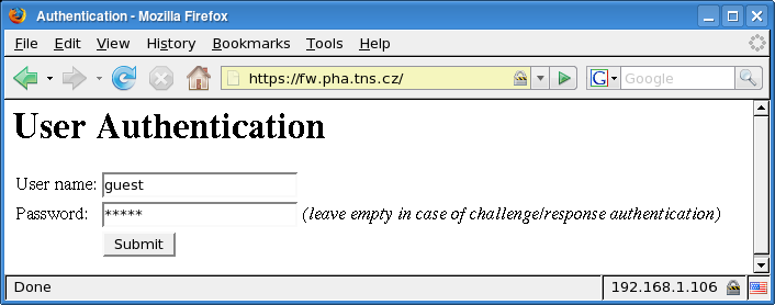
A user starts by entering an AProxy URL to a Web browser. The AProxy returns an authentication dialog, as displayed in Figure 5.52, “The user authentication dialog of the HTTP authentication proxy”. The user fills in their login name and password and clicks . If a challenge-response authentication protocol is used[35], the user must fill in the login name only. The AProxy then displays a challenge and the user enters the response (obtained, e.g., from a hardware authentication token). If the authentication succeeds, a new session is initiated and the AProxy forwards the original HTTP request to the destination server. Further requests do not require reauthentication and are transparently passed to the server. The user must authenticate again only if the session expires because of a timeout. It is also possible to log out and terminate the session explicitly by accessing a special logout URL, as shown in Figure 5.53, “The logout confirmation message of the HTTP authentication proxy”.
The HTML authentication forms displayed by the AProxy are very
simple, but their appearance is easy to modify. Form templates
are stored in the
/usr/local/kernun/conf/samples/error_documents directory.
The template files are: aproxy-password-form.html
(the form with user name and password fields),
aproxy-password-form.html (the form with a response
field for challenge-response authentication), and
aproxy-logout.html (the logout message).
Important
The AProxy uses cookies to track sessions. The cookies are added to HTTP response messages by the proxy, but they appear to the client as coming from the server. The session cookies are then extracted by the proxy from the requests. As a cookie received from a server is never sent to other servers, it is impractical to use the AProxy for authentication of clients in the internal network accessing Web servers in the Internet.
Many application protocols do not support user authentication on a proxy. Even in protocols with a proxy authentication mechanism it may be undesirable to use it in some situations. Nevertheless, we may still want to perform access control and network usage monitoring for individual users. The out-of-band authentication (OOBA) provides a solution in such cases. It is based on the fact that for any network protocol, the proxy knows the IP address of the client machine. The OOBA simply binds user names with IP addresses. There is an OOBA server, which maintains a table containing pairs of user names and IP addresses. When a proxy accepts a new network connection, it sends the client IP address to the authentication server and receives the corresponding user name or the information that no user is authenticated from that IP address. As is the case with other authentication methods, the user name can be used as a condition for ACL selection.
Note
As the out-of-band authentication cannot distinguish connections from a single IP address, more than one user cannot be authenticated on a single client machine at the same time. For this reason, computer accounts (i.e. users whose name ends with a dollar) are not automatically added to the OOB session table. On the other hand, one user can be authenticated on many machines simultaneously.
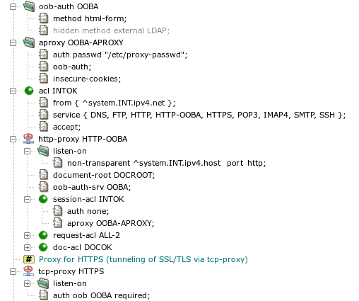
A sample configuration of the OOB authentication is displayed in
Figure 5.54, “Configuration of the out-of-band authentication”, with
http-proxy HTTP-OOBA serving as the OOB
authentication server, and tcp-proxy HTTPS, which
allows access only to users authenticated by the OOBA. The
oob-auth OOBA section
defines parameters of the OOB authentication. Only the authentication
method is specified in this example. See
auth(5) for description of all available
parameters. This session is referenced in
http-proxy HTTP-OOBA by the
oob-auth-srv item. The HTTP proxy is switched to the OOBA
mode by adding the oob-auth item to an aproxy
section and referencing this section by a session-acl.
In the sample configuration, a password file is used to check user names
and passwords. As the OOBA is performed in the internal network, which is
assumed to be secure, plain HTTP without SSL/TLS is used, which is why
insecure-cookies needs to be added to the
aproxy section.
The html-form OOB authentication method is selected in
the sample configuration. It authenticates users interactively in the
same way as the AProxy (Section 14.7, “HTTP Authentication Proxy”). The alternative
option, external (marked as
hidden in the sample configuration),
is to import the list of authenticated users from a server in the
network. The external OOBA is fully transparent. Users do not have to do
anything special, they just log in to the server that provides data to the
Kernun UTM OOB authentication server. Out of the box, Kernun UTM contains the
ooba-samba(1) script, which implements integration
with Samba.
The tcp-proxy HTTPS proxy uses the OOB
authentication and accepts authenticated users only. The
OOBA is activated by setting the oob method in the
auth item. The OOBA server and proxies that provide OOBA
communicate via a session table file. Therefore, they must all reference
the same file in the oob-auth sessions they use. If no
file is specified, as in our example, a common default file will be
used. The authenticated user name could be matched by
a session-acl. Another way to reject
unauthenticated users without creating a denying ACL for them is to add
the required parameter to the auth item. It
causes immediate termination of sessions initiated by unauthenticated
users, even before ACL matching begins.
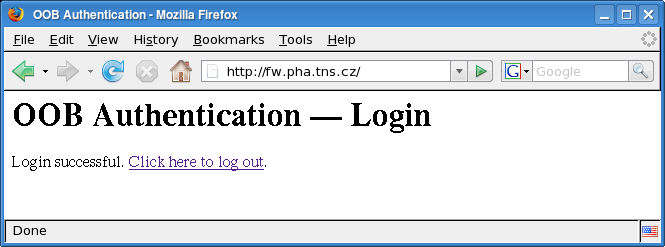
When the html-form OOBA method is used, a user must
access the authentication page (Figure 5.52, “The user authentication dialog of the HTTP authentication
proxy”) by
opening the OOBA server URL in a Web
browser. After entering a valid name and password, a login confirmation
page is displayed, see Figure 5.55, “Login to the OOB authentication server”. It contains
a link that can be used to log the user out. Like in the case of AProxy,
the authentication pages displayed by the OOB authentication server can be
changed by modifying template files in
/usr/local/kernun/conf/samples/error_documents.
There are two more OOBA authentication forms, ooba-login-confirm.html
(login confirmation) and ooba-logout-confirm.html
(logout confirmation), in addition to the AProxy ones, which are reused.
Kernun UTM can cooperate with the Dr.WEB or ClamAV antivirus programs
and any other antivirus program that supports ICAP protocol, e.g. Kaspersky
Anti-Virus for Proxy Server. This tutorial describes the configuration
of Kernun UTM only (that is, not the installation and configuration of the
antivirus programs). The complete configuration file is located in
/usr/local/kernun/conf/samples/cml/antivirus.cml.
The ClamAV antivirus program can be installed either directly on Kernun UTM or on any other machine connected via the network. The administrator of Kernun UTM can choose either of two ways to transport files between Kernun UTM and ClamAV:
clamav-net: Files to be checked by the antivirus are sent to the antivirus via the TCP connection.clamav-file: Files to be checked by the antivirus are stored on the local file system. This option can be only used if the antivirus program is running on the same machine as Kernun UTM. The directory where the files are stored is defined by thecomm-direlement (which defaults to/data/tmp/antivirus). Kernun UTM does not create the directory (it must be explicitly created by the administrator), and proper permissions need to be set (i.e., the directory must be writable byproxy-user).
The IP address and the port the antivirus program listens on
are specified in the section antivirus on the
system level of Kernun UTM's configuration, as
shown in Figure 5.56, “Configuration of the connection to the antivirus program” (we
suppose ClamAV listens on localhost's port 3310). It is possible
to limit the size (max-checked-size) of files
scanned by the antivirus program. In the sample configuration, it
is 1 MB. Larger files are not scanned and the antivirus module
immediately reports the result as
SKIPPED.
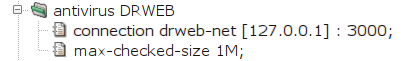
The Internet Content Adaptation Protocol (ICAP) is a lightweight HTTP-like protocol used to communicate with antivirus program. Kernun UTM makes use of it's Response Modification Mode to send data to be checked. Antivirus program sends back it's test results.
The IP address and the port the antivirus ICAP server listens
on are specified in the section antivirus on the
system level of Kernun UTM's configuration, as
shown in Figure 5.57, “Configuration of the connection to the antivirus program via ICAP”
(in this example it's 10.0.0.33 and standard
ICAP port, 1344). The third parameter of
connection item (/av/respmod
in this example) is an URI of the antivirus' Response Modification
Mode handler. Again, it is possible to limit the size
(max-checked-size) of files scanned
by the antivirus program.
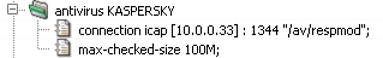
There are five possible results of a check of content by the antivirus:
- Free
The antivirus has scanned the data and has not found any virus.
- Found
At least one virus has been found.
- Skipped
The antivirus has not scanned the data. Either the antivirus itself has decided not to scan, or the file has been larger than the limit specified by
max-checked-size. No virus has been found, but the antivirus has not confirmed that the data is virus-free.- Unknown
The proxy has received a result from the antivirus, but does not understand it. It is not known whether there is any virus in the data, or not.
- Error
The proxy cannot communicate with the antivirus. This is usually caused by the antivirus not running or by misconfigured antivirus connection in the proxy.
The antivirus program can be used for online scanning of the
content transferred via ftp-proxy,
http-proxy, imap4-proxy,
pop3-proxy and smtp-proxy. There is a
slight difference between mail-processing proxies
(imap4-proxy, pop3-proxy and
smtp-proxy) and the other two
(http-proxy and ftp-proxy). In the
latter case, a special functionality is implemented that prevents clients
from reaching a timeout while very long files are being scanned. The
client is fed with chunks of the file at specified intervals until the
scanning of the file is completed.
Document scanning for the HTTP and FTP proxies is configured in
their doc-acl. The antivirus item
specifies the name of the antivirus section to be used.
The interval, chunk and
limit items can be used optionally to specify that
if scanning takes more than a certain time (5 seconds in the example),
a chunk of the (as yet unscanned) file of a certain size (up to 2,000 bytes)
is to be sent to the client at a certain interval (5 seconds). By default,
only documents for which the antivirus returns the result
free are passed by the proxy. The
doc-acl.accept-antivirus-status item can be used to specify
additional result codes, for which the checked data are to be passed, in
addition to free.
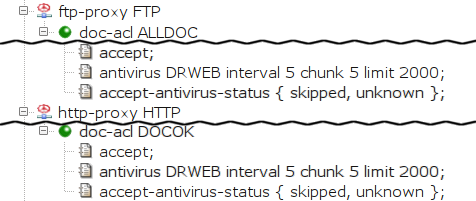
We will describe two variants of smtp-proxy
configuration, differing in the way they handle
infected mail. In this section, we show the case
when infected mail is discarded, i.e. not sent to the
recipient(s), but stored in quarantine.
In smtp-proxy, the item
use-antivirus is used to define antivirus.
Infected mail is detected in the mail-acl
sections. One of them, a mail-acl accepting all
e-mails (MAILOK), already exists in the
Kernun UTM configuration. We will create more to process messages
with various antivirus scan results (see Figure 5.59, “Discarding infected messages in the SMTP proxy”).
When smtp-proxy processes mail, the first
matching ACL is used. We must therefore place new
mail-acl sections before the existing
MAILOK.
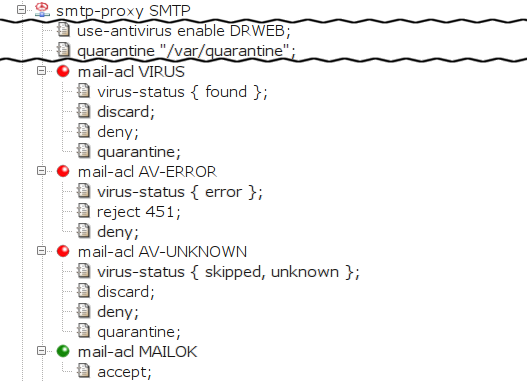
The first added mail-acl,
VIRUS, discards infected mail
and puts it in quarantine. Its only entry condition is
virus-status. It is matched if the
virus-status of the message is
found (i.e., it contains a document that
is infected by a virus). We define three actions:
discard the message (i.e., the sender
is not returned an error), deny it
(the message is not sent to the addressee) and store the
e-mail in quarantine.
The quarantine directory must be defined (the
quarantine item in the
smtp-proxy section) and created in the file
system (e.g.,
/usr/local/kernun/root/var/quarantine,
keeping in mind the smtp-proxy runs in
chroot), and writable by kernun-user. For more
information about ways of handling mail stored in quarantine,
see quarc.sh(1).
There are two more mail-acl sections.
AV-ERROR reports a transient error to the client if
the the antivirus is unable to check the message. The client can retry
sending the mail later. AV-UNKNOWN discards and
quarantines the message if the antivirus does not scan it or if the
proxy cannot understand the antivirus' reply.
Contrary to the previous example, this section
describes a way to prevent infected mail from being discarded.
This example refers to smtp-proxy SMTP-2,
which is marked hidden in the sample file[36].
This time,
smtp-proxy removes the infected documents from
the message and delivers the e-mail to the addressee, sending a BCC copy to
a special (administrator's) e-mail
address. Moreover, the subject is changed to make it obvious that a
virus was removed from the message.
smtp-proxy also stores infected mail in
quarantine. The configuration is depicted in Figure 5.60, “Replacing infected documents in the SMTP proxy”
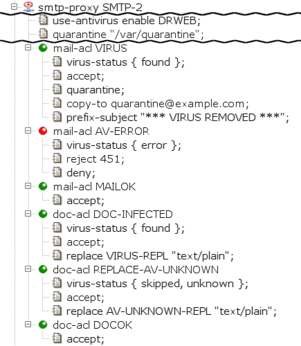
The removal of infected document is ensured by creating a
special doc-acl DOC-INFECTED section that matches
the infected documents. We place it in front of the existing
doc-acl DOCOK in order to match before the
more generic doc-acl DOCOK. The entry condition
virus-status found limits the acl
scope to the infected documents (documents marked by the
antivirus program as containing a virus). We add the action item
replace so that the matched (and therefore
infected) document is replaced by the given file. The
administrator must explicitly create this file if it does
not exist. Because the proxy is configured to run in chroot
environment, the file must be stored in the particular
subdirectory of the directory specified as
chroot-dir (in this case,
/usr/local/kernun/root/etc/shared/error_documents/).
The special behavior for infected e-mails (i.e., the
messages that contain an infected document) is defined in
mail-acl VIRUS. The entry condition
virus-status found limits the acl scope to
infected e-mails. The accept item specifies
that the e-mail should be delivered to the addressee. We specify that
the message is to be stored in the quarantine, that a BCC copy be sent to a
special e-mail address (the copy-to item) and that
the subject be prefixed with a specified text (the
prefix-subject item).
Like in SMTP, there is an additional
mail-acl AV-ERROR that returns a transient error
to the client if the mail cannot be checked by the antivirus.
Finally, doc-acl REPLACE-AV-UNKNOWN replaces
documents that are skipped by the antivirus.
In this section, we show the POP3 and the IMAP4 proxies configured to replace infected documents. See the Figure 5.61, “Replacing infected documents in the POP3 proxy” and Figure 5.62, “Replacing infected documents in the IMAP4 proxy”
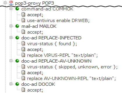
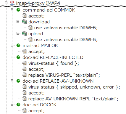
First, we instruct Kernun UTM to scan the documents transferred
through the proxy with the antivirus by specifying
the item use-antivirus. The item is specified
directly in command-acl for the POP3 proxy, whereas
for IMAP4 proxy, it is specified separately for the
download and for the upload
case.
In the second-level acl (mail-acl MAILOK), we
specify that all e-mails should be accepted. In the third-level
acl, we specify that we want to replace infected
(doc-acl REPLACE-INFECTED) and unscanned
(doc-acl REPLACE-AV-UNKNOWN) documents, and to accept
all other documents (DOCOK)[37].
Kernun UTM can cooperate with the SpamAssassin antispam software to reject or mark spam. Three more methods can be used in addition to the SpamAssassin protection: black-listing (rejection of mail from senders with addresses listed in an external database), white-listing (authorisation of the sender on his or her domain server) and grey-listing (an automatic method based on a local database). We will discuss the configuration of antispam first, and then briefly describe the individual methods in the next sub-chapter.
Like the Dr.WEB or ClamAV antivirus programs, you can install
SpamAssassin either directly on Kernun UTM or on any other machine
connected via the network. The antispam configuration in Kernun UTM is
analogous to the antivirus configuration. We define the
antispam section on the system level,
and we reference this section in the mail processing proxies
(smtp-proxy, pop3-proxy, and
imap4-proxy).
We can use the results of the antispam check in the spam-score item[38] in the mail-acl section of the spam-checked proxy.
Having configured the SPAMASSASSIN section, we
now reference it in the proxies. We replace the item no-mail-scanning (in the
command-acl section) with use-antispam enable SPAMASSASSIN 100K.
Tip
Antispam checking is a very demanding operation, and typical spam mails are quite small. You may therefore want to check only messages below a certain limit size, such as 100 kB in our case.
Because we deleted the no-mail-scanning item, Kernun UTM will search for
matching mail-acl and doc-acl sections and we must
therefore create them. (Otherwise, Kernun UTM's default reaction would be to
reject the mail.) We create a mail-acl
section that will mark spammed e-mails, but deliver them to the recipient(s).
We do so by adding an acl condition spam-score
and setting it to accept e-mails with a spam score exceeding 5.0 (we use the relational
operator ge; the Kernun UTM spam score of 5000 corresponds to SpamAssassin's
score of 5.0 multiplied by 1000). We specify that such messages will be accepted, but define
a prefix-subject item that adds a text prefix to their subject.
Finally, we add accepting mail-acl and
doc-acl and we get the configuration shown in
Figure 5.63, “Antispam protection for POP3 proxy”.
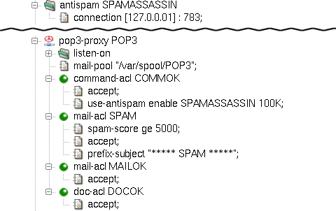
Analogously, we can add antispam support to the IMAP4 proxy.
We add the use-antispam items to both download
and upload sections, and then create the mail-acl and
doc-acl sections. Figure 5.64, “Antispam protection for IMAP4 proxy” shows the antispam
configuration of imap4-proxy.
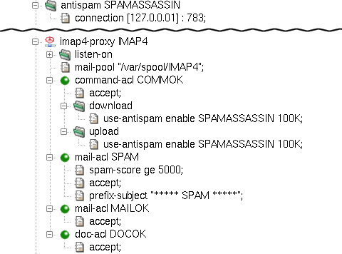
The configuration of smtp-proxy is, again,
similar to the previous cases, only this time we define the use-antispam item
right inside the proxy. In this example we show how to deny mails with too high a spam score
and store them in quarantine on the server. We do so by specifying a quarantine
item in the proxy and setting it to the path of the quarantine directory.
Remember that we work under a chrooted environment, so we need to create that directory
inside the chroot (in our example, /usr/local/kernun/root/var/quarantine).
We add a mail-acl SPAMQUARANTINE with items deny to
not deliver messages with SpamAssassin score exceeding 10, discard to not inform the sender
about the delivery failure and quarantine to place the mail into the quarantine directory.
Another mail-acl, SPAMMARK, is
used to pass e-mails with the score of 5-10, but mark it with a subject prefix.
The relevant part of the SMTP proxy configuration with antispam is shown in
Figure 5.65, “Antispam protection for SMTP proxy”.
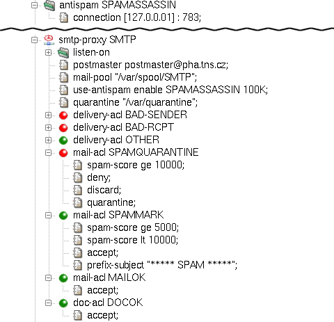
The resulting configuration of mail proxies with antispam is available in the
/usr/local/kernun/conf/samples/cml/antispam.cml sample file.
For more information on antispam configuration, see the mod-antispam(5) manual page.
Kernun UTM's smtp-proxy provides
configurable client identity checking as protection against unsolicited
mail. White-listing implemented in Kernun UTM is based on the Sender
Policy Framework (http://www.openspf.org), which checks if the
sender is allowed in the sender policy of the return path domain and thus
authorizes the sender. After inserting a white-listing item into
session-acl, the result of the matching can be used in the delivery-acl
section using the spf condition.
On the other hand, the black-listing method checks the sender's address against an external database of
forbidden IP addresses. The sender's presence in such a database (for example http://www.spamhaus.org)
means that the e-mail is denied during the session-acl phase.
The configuration of black- and white-listing is depicted in Figure 5.66, “White- and black-listing for SMTP proxy”. The list of the main
black-listing databases is defined in /usr/local/kernun/conf/samples/include/smtp-blacklist.cml.
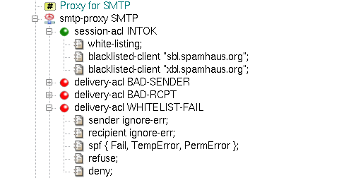
Grey-listing is a mail-filtering method that does not rely on any external database or domain information. Instead,
it creates its own database of triplets (sender IP, sender e-mail address, recipient e-mail address) and behaves according
to the state of triplet in the database. New e-mail is saved as blocked and a temporary error
answer is sent to the sender. If the sender tries to redeliver the mail within a predefined period (e.g., after some time,
but not too late), the state of the triplet changes to granted and all mail with the same
triplet will then be passed without any blocking time. The grey-listing method is configured by the
grey-listing section in the delivery-acl, and the grey-listing
section with a path item set to the filename of the grey-listing database in smtp-proxy.
A sample grey-listing configuration is shown in Figure 5.67, “Grey-listing for SMTP proxy”. For more detailed information about
the method, see the description of the
triplicator(1) tool.
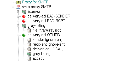
Kernun UTM provides tools to investigate and filter the contents of the passing packets. These tools make it possible for the administrator to filter the contents of the HTML and mail traffic.
The third-level ACL, doc-acl, has as an entry condition mime-type
specification (see access-control(7), configuration(7) manual pages). The content type detection can be performed using several different methods;
the administrator can set the order of the used methods globally for the whole proxy, or separately
for each of its doc-acls.
The following content-type detection methods are available:
- content-type
(Original Content-Type) — the proxy uses the type declared by the document originator in the
Content-Typeheader;- extension
(File Name Extension Mapping) — the proxy tries to guess the MIME type from the name of the document (if specified);
- magic
(Magic Number Recognition) — the proxy reads the initial block of the document and tries to guess the file type from it with help of the magic number file (see magic(5) manual page).
Note
Method magic is skipped in the http-proxy when
the response is partial and does not contain its beginning. Partial HTTP response either
contains HTTP header Range or has content-type multipart/byteranges.
The method magic is always skipped when the content-type is multipart/byteranges.
Item request-acl.delete-req-hdr-range can be used to make the server send the entire response.
The common usage of mime-type conditions is in the http-proxy, where
the administrator can forbid selected types of documents (e.g., video, applications). In our example, we will
start with the initial configuration file, as shown in Section 2, “The Initial Configuration”, and deny all documents
recognized as any of the video mime-types for the http-proxy HTTP.
First,
we need to specify the order of the used Content-Type detection methods. We add the doctype-identification
section into the http-proxy HTTP, insert the order item into
it and select the intended methods in its detail. In order to do so, we append three values magic,
extension and content-type into the doctype-ident-method-list
order field, leaving the field direction-set for unchecked (it can be used to define
different order for each of the traffic directions — upload and download).
The magic and extension methods need further configuration: the former
a magic file and the latter a file that contains the extension to the
content-type mapping database. We specify them by adding two
shared-file items pointing to the corresponding configuration files. In our example, we will use
the sample configuration file for magic located in samples/shared/magic and
the extension configuration file located in samples/shared/mime.types. We
configure the selected methods to use these shared files by inserting two new items
into the added doctype-identification section.
The magic item points to the name of the
magic configuration shared-file and the mime-types item
to the name of the extension configuration shared-file.
Having configured the order of the used
Content-Type detection methods, we can proceed to the filtering of all video documents. We do so by inserting new
doc-acl called VIDEO into the http-proxy HTTP section.
We will add it right above the doc-acl DOCOK section, so that VIDEO takes precedence.
We restrict the ACL to the video MIME type by inserting the mime-type option.
We define the set of matching MIME types in str-set type. In this example we insert a single item,
video. In a more complex situation, regular expressions can be used to define all the types
to be matched for the ACL. Finally, we need to add the deny item into the inserted
doc-acl VIDEO. Figure 5.68, “Content Type detection configuration for HTTP proxy” shows the relevant part of configuration.
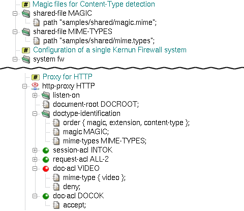
The resulting configuration file can be found among Kernun UTM samples
under the name doctype-detection.cml in
/usr/local/kernun/conf/samples/cml. For more detailed information on Content Type detection,
see the doctype-identification(7)
manual page.
Besides other tools used to filter whole packets and documents (URL filtering, antivirus checking, etc.), Kernun UTM
provides an HTML filter that filters (or replaces) elements and attributes inside an HTML document. The filter is applied
to every passing document on the third level of ACL processing, so it is applicable with all proxies that have the
doc-acl section
(http-proxy, imap4-proxy, pop3-proxy, etc.). The filter gets the
whole HTML document, and deletes (or replaces) undesirable elements and attributes according to the specified rules.
If there are no rules in the HTML filter,
the document will be passed “as-is”. If we create a rule of some type, all the matching elements (or attributes)
will be accepted/denied according to the matching rule. If no rule matches, but there is a rule of the element/attribute
type specified, the element/attribute will be denied.
For example, the administrator may want to deny all the Adobe Flash animations and replace all the URIs that refer to
“suspicious” Web sites. We create a system-level html-filter section
and name it HTMLFILTER.
Now we need to add rules that will filter the elements and attributes of the document.
First, we want to filter all the Flash animations. These can be contained in two HTML elements, embed
and object, so we need to delete these two elements, but not all of them – only those with the
application/x-shockwave-flash Content-Type. We add an embed-tag-type item, which represents
a filter rule that applies to embed tags with the corresponding content type. Now, we need to specify the
content types we want to filter (either as whole Content-Type names or using regexps) and the action that is to
be done (accept or deny). We append one value, “application/x-shockwave-flash”
to str-set val and select deny from the action combo box. Now, we have
filtered all the embed HTML elements with flash animations. We can do the same with the
object elements using the object filter item set to the same values.
The items added so far filter out the undesirable contents.
However, it may be useful to warn the users that we have changed the documents they are viewing. We can do so
using the replace- filter items, which define the content that will replace a deleted
element/attribute. For elements that can appear in both the head and body
HTML elements (such as embed and object) we can set the replace text separately for each
of the two cases. In our sample, we will create a replace-body-embed-tags item and set its value to “Flash
embed tag DENIED” and a replace-body-object-tags item and set its value to “Flash object tag DENIED
”.
We must not forget to create accepting rules for both object
and embed-tag-type that will accept all the Content Types. Otherwise, the previously added rules would
delete all the embed and object elements.
Clickjacking protection can be implemented by filtering IFRAME elements. This is done by adding iframe-tag-src
rules, which follow the convention stated above. The SRC of the IFRAME element is being matched as a regexp
(/^http:\/\/([^.]+\.)*kernun.com\// in the example matches the domain kernun.com and its subdomains).
The replacement text can be set by replace-iframe-tags.
The HTML filter provides another type of useful rules: attribute filters. These
can be used to delete (or replace) whole attributes from the document. In our example, we want to replace all the
“suspicious” URI attributes with a neutral one. We will add a new uri item rule and set it to
deny the undesired URI regexps, in our case /.*photo.*/,
/.*video.*/ and /.*warez.*/. Again, as we have created a new filter rule, we need to allow
all other URIs that do not match this rule. We add a new uri item and set it to accept
all the URIs (*). Now we add the replacement for the whole URI attribute (not only the value that is
matched in the uri item) by inserting a new replace-uri item rule and setting it to a neutral URI,
for example "href='http://www.kernun.com'"[39].
Having created the whole HTML filter, we can use it in any
proxy that has a third-level ACL doc-acl. We tell the proxy to use an HTML filter by inserting an
html-filter item with the filter's name into the proxy's doc-acl. The use of
a slightly more complex HTML filter blocking all the Flash documents and the specified URIs in the http-proxy HTTP
is depicted in Figure 5.69, “HTML filter example”.
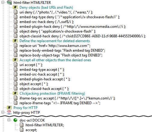
The complete resulting configuration can be found in /usr/local/kernun/conf/samples/cml/html-filter.cml.
More complex HTML filter rules are created in /usr/local/kernun/conf/samples/include/html-filter.cml.
For more information on HTML filtration, see the mod-html-filter(5) manual page.
In Section 2, “The Initial Configuration”, we created simple mail-handling proxies (smtp-proxy,
imap4-proxy and pop3-proxy), which just passed the e-mail and did not check it in
any way. Kernun UTM provides tools to decode the e-mail MIME structure and examine
each document. The mail may be scanned for viruses (see Section 15, “Antivirus Checking of Data”) and
for spam content (see Section 16, “Antispam Processing of E-mail”). These scans are added to the proxy by
inserting a use-antivirus and/or use-antispam item into the proxy
and setting them to the respective antivirus/antispam section name.
Kernun UTM has also a mail filter, which can be used to repair the MIME structure and headers of the e-mail
according to corresponding RFCs, so that other mail servers could process the mail and possibly deliver it to the recipient(s).
Errors in e-mails that are to be corrected can be specified in the mail filter. The relevant part of a sample
configuration with a mail filter is shown in Figure 5.70, “Mail filter example in use with IMAP4, POP3 and SMTP proxies”; the entire configuration can be found
in /usr/local/kernun/conf/samples/cml/mime-processing.cml.
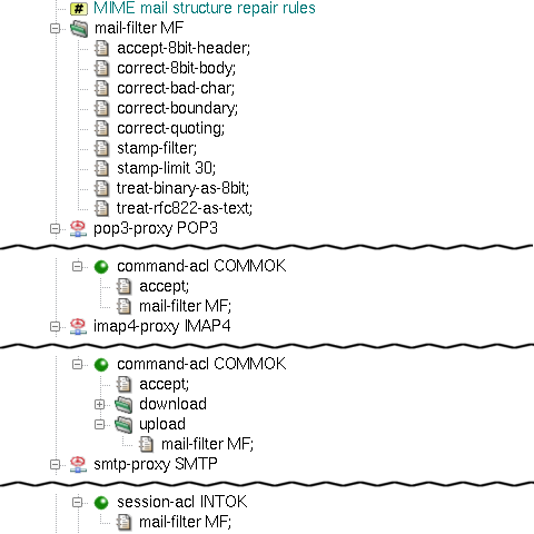
For more information on MIME filtration, see the
mod-mail-doc(5) manual page.
Kernun UTM's HTTP proxy provides several methods that can be used to change
requestURIs passed to servers and make decisions based on URIs. A URI can be
matched against regular expressions, searched in a local database
(blacklist), or evaluated by the Kernun Clear Web DataBase or by an
external Web filter. The sample configuration
/usr/local/kernun/conf/samples/cml/url-filter.cml
contains an HTTP proxy with all URI filtering methods.
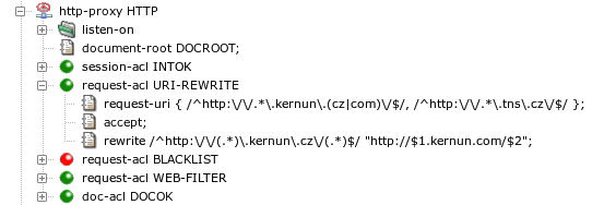
An example of the HTTP proxy that matches HTTP requests by the
request URI is depicted in Figure 5.71, “Request URI matching and rewriting”. If a request URI
matches one of the regular expressions in the string specified in the
request-uri item of
request-acl URI-REWRITE, this ACL will be selected.
It accepts the request and applies the rewrite item(s). There
can be several rewrite items. Each of them contains
a regular expression and a string. A request URI that matches the regular
expression in a rewrite clause will be rewritten to the
string. Pairs of characters dollar+digit ($1,
$2…) in the string will be replaced by parts
of the original URI matched by parenthesized parts of the regular
expressions. The rewrite item in Figure 5.71, “Request URI matching and rewriting” matches any URI containing
kernun.cz and rewrites cz to
com, leaving the rest of the URI unchanged.
In a request-acl, there are two more types of
URI-matching conditions. We have already seen
request-uri, which matches the whole URI. The other
conditions are: request-scheme (matches the scheme part
of the URI) and request-path (matches the path part of
the URI).
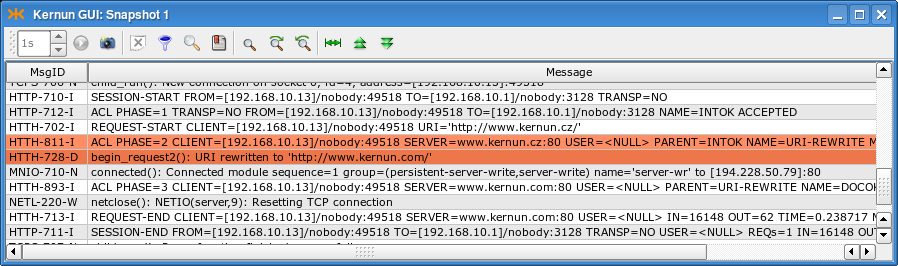
Figure 5.72, “Log of URI matching and rewriting” shows a log of an HTTP proxy
running with the configuration from Figure 5.71, “Request URI matching and rewriting” and
processing a request with URI http://www.kernun.cz/.
The two most important messages are marked. The
HTTH-811-I message informs that
request-acl URI-REWRITE was selected. The following
message confirms that the URI was rewritten to
http://www.kernun.com/.
A security policy may require to deny access to large groups of Web
servers. Adding a very large number of servers to
a request-acl.request-uri item may slow down ACL
processing significantly. A better strategy is to create
a blacklist of forbidden servers in a special
format processed more efficiently by the HTTP proxy. A blacklist must be
prepared in a text file in the format described in
mkblacklist(1). The textual blackist is then
transferred to a binary form usable by the HTTP proxy by utilities
resolveblacklist(1) and
mkblacklist(1). A binary blacklist file can be
converted back to the text format by
printblacklist(1).
A blacklist contains a list of Web server addresses (domain
names or IP addresses) with an optional initial part of a request path.
A list of categories is assigned to each address. It is possible to select
a request-acl based on a matching
blacklist item with the set of categories assigned to the
request URI by the blacklist.
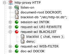
An HTTP proxy will use the blacklist database file specified by
blacklist-db in the http-proxy section,
see Figure 5.73, “A blacklist in the HTTP proxy”. If a request URI belongs to
the category chat or news, then
request-uri BLACKLIST will be selected and the
request will be denied. Other requests will be processed according to
request-uri WEB-FILTER, described in the next
section.
Note
If a proxy runs in chroot, the path
blacklist-db will be interpreted in the context of the
chroot directory.
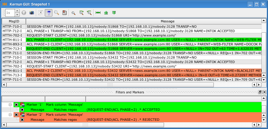
A log of an HTTP proxy configured according to Figure 5.73, “A blacklist in the HTTP proxy” is displayed in Figure 5.74, “A log of blacklist usage in the HTTP proxy”. The log messages are related to two
requests. The first request to server www.example.com does not match
categories selected in request-acl BLACKLIST and the
request is accepted by request-acl WEB-FILTER. The
second request to
news.example.com matches
a category from request-acl BLACKLIST, which rejects
the request. Note the ACL names reported in
ACL PHASE=2 messages and the log
markers that colorize accepting and rejecting messages.
Continuous updating of a blacklist so that it covers as many prospective unwanted Web servers as possible is a challenging task, greatly exceeding the capabilities of a typical company network administrator. Therefore, there are commercially available services that provide regularly updated databases of Web servers classified into many categories according to content. Kernun UTM contains one such service—the Kernun Clear Web DataBase.
Configuration of the Kernun Clear Web DataBase consists of two parts. One is used to detect URL categories and select ACLs according to the categories, the other deals with updating of the database of URLs.
The Clear Web DataBase takes a request URI and assigns to it a set
of categories. The categories can be matched by item
request-acl.clear-web-db-match in the process of
request-acl selection during an HTTP request processing.
Two examples of sections request-acl with condition
clear-web-db-match are shown in Figure 5.75, “Kernun Clear Web DataBase in the HTTP proxy”. There are three possible modes of
category matching, selectable in each condition item:
any— at least one category of the request URI matches the set of categories in the condition;all— all categories in the condition are contained in the set of categories which the request URI belongs to;exact— the request URI belongs to all the categories from the condition and does not belong to any additional category.
If the selected request-acl contains
a clear-web-db-match condition
(CLEAR-WEB in the sample configuration) and the
deny item, the proxy will return an error HTML page
containing information that the request has been denied by the Clear Web
DataBase and the list of matching categories.
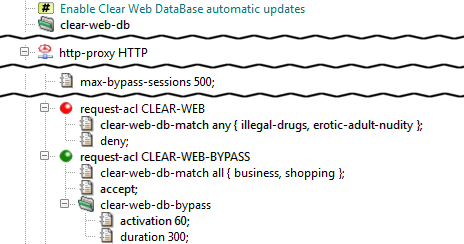
As an alternative to denying a request URI matching given categories
absolutely, the proxy provides the bypass feature, a
sort of “soft deny”. It is activated by item
request-acl.clear-web-db-bypass (used in
CLEAR-WEB-BYPASS in the sample configuration). When
a user attempts to access a Web server restricted by the bypass, an error
page is returned by the proxy, containing a link, through which
the user can obtain limited-time access to the requested server and all
Web servers that belong to the same categories. After the bypass
expiration time, which can be changed using item duration,
the error page will be displayed again. The user can then reactivate the
bypass. Each bypass activation is logged.
Bypass sessions activated by users are tracked by an internal
table managed by the proxy. The maximum number of simultaneously active
bypass sessions is controlled by
http-proxy.max-bypass-sessions. If this number is set to
0, the number of bypass sessions will become unlimited, and the sessions
will be tracked by cookies. In this case, an activated bypass is valid for
the target server and all servers in the same domain, but not for other
servers, even if they belong to the same categories.
Clients often use the HTTP proxy also for access to intranet WWW
servers. These internal servers can be located in the internal network,
using private IP addresses from ranges defined by RFC 1918 (networks
10.0.0.0/8, 172.16.0.0/12, and 192.168.0.0/16). Or they may be accessible
from the Internet, but restricted to internal users.
Such internal servers are not contained in the Clear Web DataBase
and would be categorized as unknown. In order to
distinguish internal servers from public web servers with unknown
categories, host names or IP addresses of the internal servers can be
listed in the configuration by item
clear-web-db.internal-servers. Private IP addresses from
RFC 1918 are included by specifying
internal-servers private-ip, so they need not be
written explicitly.
If a server from an HTTP request matches some element of the list of
internal servers, it will be assigned category
internal-servers. This category is not used for any
public web server included in the standard Clear Web DataBase.
The Clear Web DataBase file location in controlled by
clear-web-db.db, which defaults to
/data/var/clear-web-db if not set. The database
file is copied (or hardlinked, if possible) automatically to any chroot
directories by the database update script and when the configuration is
applied.
Although it is possible to update the Clear Web DataBase data manually
by copying an updated clear-web.db file to the database
directory, it is recommended to use the provided update script
clear-web-db-update.sh for this purpose. It downloads the most
appropriate full database and/or applies any incremental updates to get the
most recent version of the database, minimizing the amount of downloaded data.
To use this feature, you need to have valid download credentials. These are
configured by clear-web-db.credentials.
If not set, the serial number from the license file is used as both
the username and the password.
The Clear Web DataBase data update script can be executed either
manually by running clear-web-db-update.sh from the root
console (Kernun console in the GUI), or automatically by cron in periodic
intervals. Periodic updates are enabled by placing the clear-web-db
(usually empty) section in the system configuration.
If no record is found for a requested URL in the Clear Web DataBase, the “unknown” result is reported and matched in ACLs. A valid list of categories will be returned for repeated requests to the same URL only after the server becomes a part of the Clear Web DataBase downloaded in some future update. As an option, there is a faster way how to obtain categories for servers not yet known. It is possible to enable the cwcatd daemon that performs automatic local categorization of web pages.
If categories for a requested URL are not found in the Clear Web DataBase, the URL is appended to a queue that is processed by daemon cwcatd. The daemon reads uncategorized URLs from the queue. For each URL, it tries to download the referenced web page. The downloaded page is passed to an automatic categorizer, which tries to assign categories according to heuristics applied to the page content. If it succeeds, the result is stored in a local database. Future requests to a locally categorized server will get categories assigned according to the local database. If categories of the server appear in the downloaded Clear Web database in its periodic update, the result of the automatic local categorization will not be used any more.
Categories discovered automatically by the cwcatd daemon are not as correct and reliable as the contents of the Clear Web DataBase maintained by experienced human operators. But on the other hand, results of the automatic categorization are available almost immediately after the access to a web page with unknown categories.
Automatic categorization of web servers is enabled by adding
subsection local-db to the configuration section
clear-web-db. It instructs the
http-proxy and the icap-server to
enqueue URLs with unknown categories for processing by
cwcatd and to use the results of automatic
categorization. The cwcatd daemon is enabled by adding
section cwcatd.
The Clear Web DataBase or the local database contain the following set of categories:
- Advertisement
Advertising agencies, servers providing advertising banners
- Alcohol / Tobacco
Alcohol, tobacco, breweries
- Arts
Galleries, theaters, exhibitions
- Banking
Banks, Internet banking
- Brokers
Stock exchange information, stocks purchase and sale
- Building / Home
Construction, architecture, e-shops with construction materials and equipment
- Business
Corporate websites, offering actual services and products, Web pages referring to companies (parked domains)
- Cars / Vehicles
Web pages of motorists, motorcyclists, aviators, sailors, producers, vendors and enthusiasts of transportation vehicles
- Chats / Blogs / Forums
Chats, personal blogs, discussion forums
- Communication
Information and communication technology, services of Internet providers, telephone operators, SMS gateways, phonebooks
- Crime
Committing crime, crime protection
- Education
Education, science, research
- Entertainment
Entertainment and sports centers
- Environment
Weather forecasts, live webcams, environment protection, ecology
- Erotic / Adult / Nudity
Erotic acts, half-naked up to naked bodies, erotic tales
- Extreme / Hate / Violence
Attacks against individuals or groups of people, deviations (sadism, masochism, etc.), violence on humans or animals
- Fashion / Beauty
Clothing, body care, make-up
- Food / Restaurants
Restaurants, recipes
- Foundations / Charity / Social Services
Help to handicapped, addicted, underprivileged people or people with special needs, families and children
- Gambling
Gambling for money
- Games
Online and offline games
- Government
Government organizations, agencies, ministries, communes
- Hacking / Phishing / Fraud
Web pages of cracking groups, malicious software, exploitation guides. Does not include anti-hacking and anti-phishing protection
- Health / Medicine
Electronic pharmacies, hospitals, relaxation, massage, spa
- Hobbies
Thematic hobby/interests pages
- Humor / Cool
Humor, jokes, pranks
- Illegal Drugs
Drugs, narcotics
- Instant Messaging
Real-time message transfer
- Insurance
Insurance companies
- Internal Servers
Internal web server, includes private (RFC 1918) IP addresses and servers declared as internal in the configuration
- IT / Hardware / Software
Hardware and software retail, service, support
- IT Services / Internet
IT and Internet products, services, domain names
- Job / Career
Human resource agencies, job offers
- Kids / Toys / Family
Advice, instructions, websites for kids and family
- Military / Guns
Historic information, army-shops
- Mobile Phones / Operators
Mobile phones and accessories, telephone operators
- Money / Financial
General financial consultancy, financial servers
- Music / Radio / Cinema / TV
Web pages of music bands, pages about music and movies, TV guides, cinema programme
- News / Magazines
Live news, tabloids, journals. Does not include Web pages aggregating news from other sources
- Peer-to-peer
Peer-to-peer networks for data transfer (software, music, movies)
- Personal / Dating / Live Styles
Personal Web pages, pages of musicians and bands, gossips
- Politics / Law
Web pages of political parties, pages about politics and law
- Pornography
Videos for download, photos, e-shops
- Portals / Search Engines
Internet search engines, covering either a large number of areas or specific fields. Does not include Web pages searching their own site only
- Proxies
Servers that provide access to other Web pages to their clients, e.g. in order to hide the client's identity or to circumvent network access restrictions
- Real Estate
Real estate servers, companies
- Regional
Web pages of municipalities and regions
- Religious / Spirituality
Churches, religious themes, esoteric pages
- Sale / Auctions
Auctions, bazaars, sale and purchase
- Sects
Sects
- Sex Education
Professional information about sex
- Shopping
Stores, advertising sites, e-shops with a shopping cart, which must be operated at the top-level domain
- Social Networks
Social structures made up of people connected by friendship, family, common interests and other relations
- Sports
All sports and disciplines, including extreme sports
- Streaming / Broadcasting
Internet TV and radio
- Swimwear / Intimate
Lingerie, underwear, swimsuits, e-shops, producers and sellers
- Translation Services
Online translation, translational services
- Travelling / Vacation
Timetables, travel agencies, public transportation companies, castles, chateaus
- Uploading / Downloading
Online data storage, photo albums, file-sharing servers
- Warez / Piracy
Illegal distribution of copyright-protected content, links to software, serial numbers, movies, password exchange forums
- Web Based Mail
Free Web-based mail providers
- Web Hosting
Web sites providing space on their servers to third parties
In addition to using the internal Kernun Clear Web DataBase, it is possible to cooperate with an external Web filtering service. Only one type of such a service is supported—the Proventia Web Filter. It is considered a legacy feature and Kernun Clear Web DataBase is recommended as replacement.
Proventia Web Filter runs separately from Kernun UTM on a machine with a Microsoft Windows, Linux, or FreeBSD (with Linux emulation) operating system. It is configured by its own graphical management console, available for Microsoft Windows. In order to work with Kernun UTM, Proventia Web Filter must be configured as described in section Web Filter of manual page http-proxy(8). Especially, ICAP Integration must be enabled. Moreover, if the Web filter rules take user names into account, User Profile Support must be enabled.
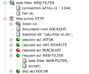
The relevant part of HTTP proxy configuration is depicted in Figure 5.76, “An HTTP proxy configured for use of an external Web filter”. The parameters of the connection to the Proventia Web
Filter server are specified by section web-filter. Note
the port number 1344, which is used by default for the ICAP protocol by Proventia
Web Filter. The sample configuration contains also a fail-ok
item, which means that all requests are to be accepted if Kernun UTM
cannot communication with the Web filter. Without this item, all requests
would be rejected until the connection to the Web filter would be restored.
Requests that are accept-ed by
a request-acl with a web-filter item will
be forwarded to the Web filter server. If the Web filter accepts the
request, the proxy will continue with the normal request
processing[40].
If the Web filter rejects the request, the proxy will terminate the processing
of the request and return an error HTML page to the client. An
example of a Web site blocked by the Web filter is shown in Figure 5.77, “A Web server blocked by the Web filter”.
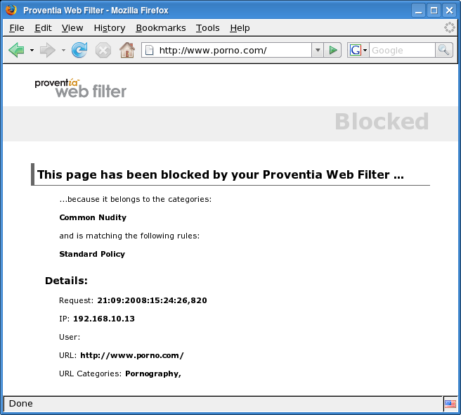
Kernun UTM, namely the http-proxy, provides means for
inspection of the HTTPS traffic. HTTPS inspection is available for both
transparent and non-transparent connection mode.
An example of the http-proxy configured for HTTPS
inspection is available in the
/usr/local/kernun/conf/samples/cml/https-insp.cml file. The
example demonstrates the following scenario:
Both HTTP and HTTPS requests are handled by the proxy.
Both transparent and non-transparent mode is provided.
The server certificate is verified by the proxy.
There is a list of server exceptions, for which the inspection is not performed.
There is a list of client exceptions, for which the inspection is not performed.
The configuration described in this section is intended for providing access to an a priori unknown set of HTTPS servers. For example, access of clients in the internal network to HTTPS servers in the Internet. If you need a secure tunnel between two points or HTTPS to a single server, the SSL/TLS configuration from Section 13, “Secure Communication Using SSL/TLS” may be more appropriate.
HTTPS uses certificates as a means to verify the server identity. HTTPS inspection (by its nature) breaks into the connection between the client and the server, which would be detected by the client and reported as an “Untrusted connection” warning to the user. To prevent this issue, the proxy generates a new certificate which mimics the original certificate. It is issued by the certification authority (CA) controlled by the Kernun UTM. By importing this CA to the list of trusted CAs of the client browser the above mentioned “Untrusted connection” warning is prevented.
There are two CAs needed for proper work of the HTTPS inspection: GOOD and BAD. The HTTP proxy selects one of them for signing the certificate that is presented to the client as the server certificate.
The GOOD CA is used for servers, whose certificates were successfully verified by the proxy. The clients are expected to import the GOOD certificate as the trusted certification authority. The BAD CA is used for servers, whose certificates cannot be verified by the proxy. The clients MUST NOT import the BAD certificate.
As the result, the web pages, whose server certificate was succsessfully verified by the proxy are presented with certificates signed by the GOOD CA to the client. The client accepts them without complains, because the client trusts the GOOD CA.
By contrast: web pages, whose server certificate cannot be verified by the proxy, trigger the “Untrusted connection” alarm, since they are presented to the client with the certificate signed by the BAD CA, which the client does not trust.
The configuration is shown in figure Figure 5.78, “Certification authorities for HTTPS inspection”. The GOOD CA and the BAD CA are provided to
the proxy in the section fake-cert as item
fake-cert.auth-ca (the GOOD CA), and item
fake-cert.fail-ca (the BAD CA). Besides the two CA, there
is also a private key needed for signing the faked certificates. The key is
specified in section fake-cert.key.
The proxy uses the list of the trusted CAs for verifying the server
certificates. The list is presented in the section
SSL-INSP-SERVER-SSL. The default list of the trusted CA is
provided by Kernun in
/usr/local/kernun/conf/samples/cert/dist_auth_cert.pem.
This list is the root certificate bundle with certificates merged from
Internet Explorer and the Mozilla Project. Main Czech and Slovak certification
authorities are included as well. If you need to modify the list, copy the file
to another location and change the path for the
shared-file SSL-INSP-AUTH appropriately. The file contains
concatenation of certificates in the PEM format, so you can delete existing
certificates or append new ones using any text editor.
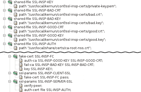
Note
The CA can be created by command mkcert.sh, for example:
mkdir /usr/local/kernun/conf/ssl-insp-certs cd /usr/local/kernun/conf/ssl-insp-certs mkcert.sh -g . -c "Kernun SSL Inspection" -F good.crt -K good.key mkcert.sh -g . -c "Server verification failed!" -F bad.crt -K bad.key
The private key needed can be created by command openssl, for example:
cd /usr/local/kernun/conf/ssl-insp-certs openssl genrsa -out private-key.pem 2048 -nodes
When both transparent and non-transparent HTTPS is used in a single
http-proxy, several session-acls and
request-acls are used to internally transform the
non-transparent traffic to transparent as well as to transform the HTTPS to HTTP
by inspecting the SSL, or to apply access control without inspecting the SSL.
After the transformations, a single set of request-acls is used
to implement the security policy.
HTTPS traffic can be:
Accepted without HTTPS inspection. The proxy establishes TCP tunnel between client and server, ending the ACL processing at
request-acllevel.Blocked without HTTPS inspection. In transparent mode, TCP connection to the client is reset before connecting to the server. In non-transparent mode, an error message is sent to the client.
Accepted in HTTPS inspection. The proxy decrypts the SSL/TLS, processes the HTTP communication and re-encrypts it afterwards. The decrypted HTTP communication is processed the same way as (both transparent and non-transparent) HTTP. When different behaviour is desired,
session-aclitemconnect-session-aclcan be used to detect thesession-aclthat accepted the HTTPS connection.Denied in HTTPS inspection. Proxy decrypts and re-encrypts the HTTP communication. Proxy can either send the client properly encrypted error document or send the requested server response signed by BAD CA as described by Section 19.1, “Certificates”.
Figure 5.79, “HTTPS inspection ACL flow” provides the schema of ACL flow during the processing of HTTP and HTTPS traffic in both transparent and non-transparent mode.
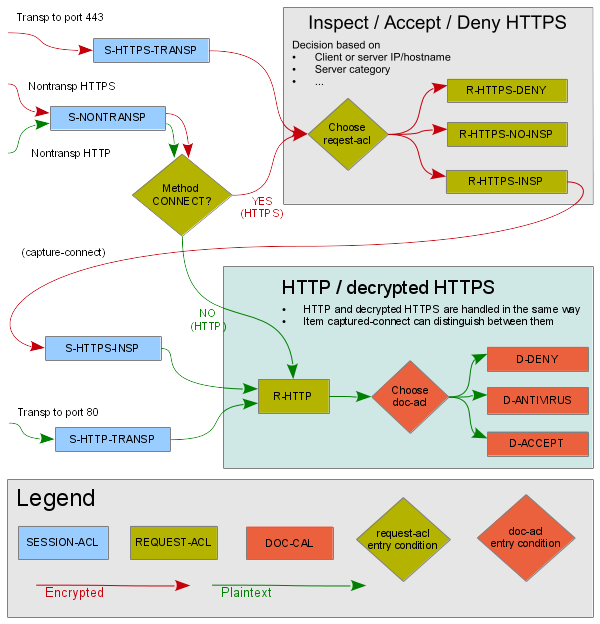
The http-proxy by default expects the client to send
an HTTP request, it can be told to expect TLS by specifying either
sni-insp or client-ssl in
the session-acl.
In transparent HTTPS, server hostname is specified in HTTP protocol which
is encrypted. However, it is usually also specified in SNI in the first TLS
message which is not encrypted yet. See Section 19.5, “SNI inspection in HTTPS” for more
details. In order to obtain the server hostname from TLS layer before HTTPS
inspection, item sni-insp is used. If an exception from HTTPS
inspection takes effect, the proxy establishes TCP tunnel to the server.
If the traffic is to be HTTPS inspected, item
capture-connect is used to make the proxy virtually close the
current session and reexute it. Afterwards, HTTPS inspection is turned on by
referencing the client-ssl section which defines item
fake-cert. Subsequent request-acl processes
the request as if it was plain HTTP.
The configuration of both transparent and non-transparent modes is shown
in Figure 5.80, “HTTPS inspection configuration”. The session-acl
S-HTTPS-TRANSP uses the item sni-insp to obtain server
name as well as to validate the first SSL/TLS message. Exceptions from
SSL inspection are defined in request-acls
R-HTTPS-NO-INSP-CLIENTS and
R-HTTPS-NO-INSP-SERVERS. Item request-method
with value CONNECT can be used here because of item
sni-insp which simulates the CONNECT method.
Item capture-connect in
request-acl R-HTTPS-INSP makes the proxy virtually close the
current session and reexute it, which results in session-acl
S-HTTPS-INSP getting matched because of item
captured-connect. The session-acl S-HTTPS-INSP
uses the client-ssl SSL-INSP-CLIENT-SSL and server-ssl
SSL-INSP-SERVER-SSL. See Section 19.1, “Certificates” for
details on these ssl-params sections.
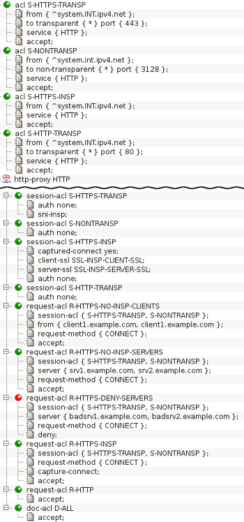
In non-transparent mode, HTTPS is recognized by HTTP request method
CONNECT. Server hostname is specified in the enveloping HTTP so SNI inspection
is not needed. Special item capture-connect is used for
handling CONNECT requests. Afterwards, it is handled by the means described
above in Section 19.3, “Transparent mode”.
This section describes Server Name Indication (SNI) inspection that can be used to obtain server name from TLS handshake for usage in request ACLs. It is intended to be used in transparent HTTPS, because in non-transparent HTTPS, server hostname is specified in the enveloping HTTP.
When a client connects to an HTTPS server, the first message (SSL/TLS ClientHello) usually contains server hostname (SNI) that the server uses for detecting service requested by the client, because multiple hostnames can be hosted on a single IP address. SNI was introduced in TLS 1.0 and is optional, it is missing for example when user accesses an HTTPS web server using IP address instead of a hostname.
When SNI inspection is configured in session ACL, the first message from client is parsed. When it does contain SNI, server hostname and URI is changed from an IP address to a hostname for usage in request ACL. Afterwards, as described at Section 19.2, “HTTPS inspection ACL flow”, HTTPS inspection can be performed, the connection can be accepted without HTTPS inspection or the connection can be denied.
The result of SNI inspection can be used in request ACL item
sni-result which has values:
specifiedThe request was a TLS 1.0 or higher ClientHello that contained SNI. Server hostname and URI for the subsequent request ACL was changed from an IP address to the hostname from SNI.
unspecifiedThe request was a TLS 1.0 or higher ClientHello that did not contain SNI. Server hostname and URI remained unchanged for request ACL matching.
ssl3The request was a SSLv3 ClientHello that did not contain SNI because it is not in the SSLv3. Server hostname and URI remained unchanged for request ACL matching.
skypeThe request was traffic specific for Skype. Server hostname and URI remained unchanged for request ACL matching. The request was either an invalid empty TLS 1.0 handshake message or TLS 1.0 ClientHello in SSLv2 record layer. Skype uses these requests for registration to the Skype network and for authentication. For the communication itself, Skype uses standard HTTPS so both
skypeandspecifiedmust be permitted in order for Skype to work. Skype can handle HTTPS inspection as well.unknown-protocolThe request was an unknown protocol or malformed request so the SNI was not inspected. Server hostname and URI remained unchanged for request ACL matching.
The http-proxy can be used to provide access to an
internal web server for clients in the Internet. When HTTPS is used, the proxy
responds to the client with a TLS server certificate immediately after receiving
the first message from the client, the ClientHello. If the proxy provides access
to multiple internal web servers, it is necessary to select the correct server
certificate for sending. That can be achieved by inspecting the SNI received in
the ClientHello.
An example of reverse HTTPS proxy configuration is shown in
Figure 5.81, “HTTPS termination global configuration” and
Figure 5.82, “HTTPS termination proxy configuration”. The full configuration is located in
/usr/local/kernun/conf/samples/cml/https-termination.cml.
It describes an http-proxy that provides access to two web
servers, server A and server B, located in internal network for clients in
Internet. The clients are forced to use HTTPS when communicating, the proxy uses
HTTP with server A and HTTPS with server B.
The proxy listens on the external network interface for connections from
clients in the Internet. When a client connects, session-acl
HTTPS-REVERSE-SNI-INSP performs SNI inspection. After the SNI
inspection, the following request-acls have its value available
in item server. The proxy chooses
a request-acl from CAPTURE-CONNECT-CRT-A or
CAPTURE-CONNECT-CRT-B which both perform
capture-connect.
During the capture-connect, the proxy virtually closes
the session and reexecutes it, entering session-acl phase once
again. One of session-acls
HTTPS-REVERSE-OK-CRT-A and
HTTPS-REVERSE-OK-CRT-B is selected based on the
request-acl that performed the capture. The selected
session-acl also responds to the client's ClientHello with the
specified server certificate and finishes the TLS handshake.
Now the proxy has TLS layer terminated and it is processing plain HTTP. It
selects either request-acl A-PERMIT or
B-PERMIT based on the address specified in HTTP request line.
The selected request-acl relays the HTTP request to one of the
servers located in the internal network. The server can be either HTTP or
HTTPS. In the example server A is HTTP while server B is HTTPS.
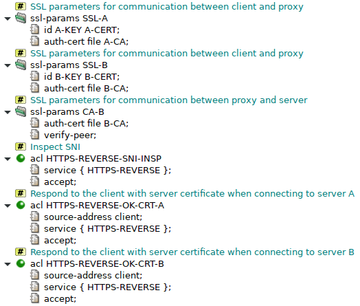
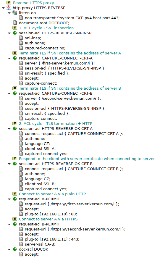
Kernun UTM provides module Adaptive Firewall that detects and blocks suspicious traffic.
According to the configuration, it can either detect and log suspicious network traffic (in IDS mode), or also block it (in IPS mode). For detailed description of the IDS/IPS system, see adaptive-firewall(7) and ips(7).
An example of Adaptive Firewall configuration is shown in Figure 5.83, “Adaptive Firewall”. The complete sample
configuration is available in the /usr/local/kernun/conf/samples/cml/ids.cml file.
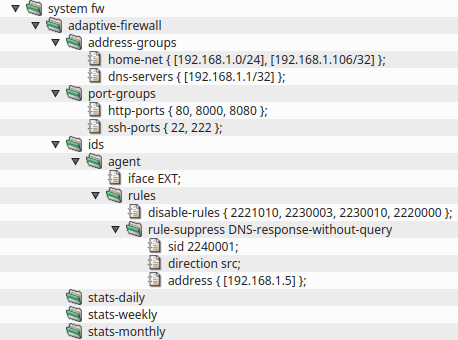
Adaptive Firewall consists of two parts, ids and ips. IDS is composed of
several possible detectors, agent, honeypot and watchdog.
Both IDS and IPS have their own databases that contain detected IP addresses (in case of IDS) or blocked IP
addresses (in case of IPS).
IDS agent is an application that performs advanced inspection of network traffic by using
complex rules downloaded from a central server to monitor traffic on interfaces specified by item
iface. The rules are configured in section
system.adaptive-firewall.ids.agent.rules while the rules download is configured in section
system.update. IDS agent uses configuration file
samples/shared/ids-agent.yaml by default. It is possible to provide a custom configuration
file by specifying a shared-file agent.engine-cfg-file. Note that the file is processed by
Kernun to propagate CML configuration, namely it adds logging, specified interfaces and path to the downloaded
rules.
Honeypot is a detector that listens on given IP address that is not used for any other
purpose. A client that tries to connect to this IP address is assumed to be an attacker and is reported to
the IPS part of Adaptive Firewall.
Watchdog is a detector that monitors given files for occurences of given string patterns. It
can be used for example to detect attackers that are trying to brute-force an SSH autentication. Configuration
of this scenario can be seen in samples/include/sshd-watchdog.cml
IPS is enabled by the presence of section adaptive-firewall.ips. When enabled, the IP
addresses reported by various IDS detectors are blocked by packet filter. Every minute, IPS decides which
addresses to add from the IDS database to the IPS database and which addresses to remove from the IPS database
because they were not seen for a long enough time, which can be controlled by item
record-lifetime.
In order to increase the success rate of rules, it is possible to tell the IDS agent more about the network it
is operating in. Sections agent.address-groups and agent.port-groups are
designed for this purpose. Most rules refer to variables that can be defined here.
Traffic analysis is based on rules that describe suspicious traffic. It is desirable to update the rules
regularly. An automatic rule download system is available in Kernun UTM. This option can be configured with the
rules-download section, which describes the rules download policy. By default, it is
enabled and it uses Kernun rules. Use item schedule to define the update schedule. Item
source defines the source of the rules. More items can be specified in order to finetune
the rules download.
If you are using Kernun rules, it is highly recommended to enable feedback-upload to send
the feedback containing matched rules back to Kernun server. The matched rules are used to improve the
Kernun rules database in order to achieve high success rate of the IPS module.
Even though the rules provided by Kernun are thoroughly tested to eliminate false positive matches, they can
still happen. Therefore, the administrator can modify the downloaded rules by items in the
rules section. It is also possible add custom rules by specifying items
add-rule or include-rules.
A rule that is distributed as disabled can be enabled by item enable-rules. A disabled rule
is commented out in the downloaded rule file so the IPS engine would otherwise ignore it.
When disabling a rule, the administrator has more options. A rule can be disabled unconditionally by item
disable-rule or only for certain IP addresses by item rule-suppress. It is
also possible to disable all rules for certain IP addresses by item global-suppress.
In IPS mode, it is sometimes desired to change the rule action from alert to
drop or reject. This can be done by items
change-rules-to-drop and change-rules-to-reject.
Items rule-rate-filter and global-rate-filter can be used to change the
rule action after the rule matched a certain number of times within a specified time frame. Similarly, items
rule-threshold and global-threshold alter the rule so it is applied only
after it matches a certain number of times within a specified time frame.
When the above methods are not sufficient, it is also possible to modify a certain rule by providing a
regular expression and a replacement string in item modify-rules.
Kernun UTM can control the amount of bandwidth consumed by various types of network communication. This feature is known as traffic shaping. Traffic shaping is based on a division of the available network bandwidth into queues of various capacity. The traffic shaping rules then assign outgoing network packets to queues. A queue controls how fast a packet will be sent out. Traffic shaping in Kernun UTM is implemented using the altq(4) framework.
Important
Traffic shaping works only for packets sent by Kernun UTM to a network, internal or external. It is not possible to limit the rate of reception of incoming packets. It is therefore impossible to limit the download speed from the external to the internal network by queuing received packets on the external interface; packets sent by the internal interface must be queued instead.
We will describe a simple traffic shaping configuration aimed at limiting the bandwidth usage by SSH communication of clients in the internal network with servers in the external network, and limiting the download speed of selected HTTP communication. We assume that the maximum speed of both the internal and external network interfaces is 100 Mbits/s.
Let us specify our sample objectives more precisely: 1. For any SSH connection, i.e., a connection to a server in the external network on port 22, we want to limit the data flow to 10 Mbits/s in each direction. 2. Clients from a subset of the internal network accessing HTTP servers in the external network are to have the download speed limited to 10 Mbit/s for selected request URIs at certain time intervals. The 10 Mbit/s limit will be shared by the SSH and HTTP communication.
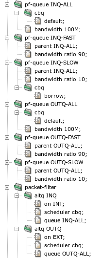
The first step in traffic shaping configuration is to define
the set of queues. This is done by adding sections
system.pf-queue and
system.packet-filter.altq, see Figure 5.84, “Configuration of traffic shaping queues”. All our queues use the cbq (Class
Based Queueing) scheduler, i.e., the bandwidth of a network interface
is divided into a hierarchically organized tree of queues. We define a parent
queue on the internal network interface by section
pf-queue INQ-ALL and subsection altq of
section packet-filter. The pf-queue section
selects the cbq scheduler and specifies (using the default parameter)
that the queue will get all packets that are not explicitly assigned to
another queue. The queue can use all 100 Mbits/s available for the
interface. Subsection altq specifies that the parent queue,
and also its child queues, will handle packets sent to the internal
network via the INT interface. The bandwidth is split
between two child queues defined by pf-queue INQ-FAST
(90 Mbits/s) and pf-queue INQ-SLOW
(10 Mbits/s). Moreover, queue INQ-SLOW can
borrow unused bandwidth from other queues. Similarly, there
are three queues OUTQ-ALL, OUTQ-FAST, and
OUTQ-SLOW[41] for handling packets
sent to the external network via the EXT interface.
The /usr/local/kernun/conf/samples/cml/altq.cml file
contains the complete sample configuration.
For detailed description of ALTQ parameters, refer to
packet-filter(5) and
pf.conf(5).
Traffic shaping can be done at two levels, using either packet filter, or queue selection in proxy ACLs. We will use each of the levels for one of our sample objectives.
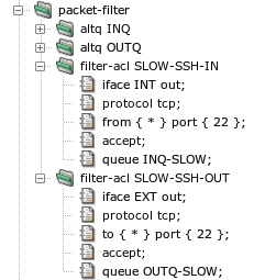
The SSH communication speed can be limited using packet filter ACLs, as depicted
in Figure 5.85, “Traffic shaping by packet filter ACLs”. Packets in the direction from the server
to the client are matched by filter-acl SLOW-SSH-IN as
they are sent by tcp-proxy SSH to the internal
network. This filter-acl matches packets sent (direction
out) on interface INT, from any server
IP address and from the server port 22. The packets are accepted and queued via
queue INQ-SLOW. Similarly,
filter-acl SLOW-SSH-OUT matches packets in the direction
from the client to the server as they are sent by
tcp-proxy SSH to the external network. It matches
packets sent (direction out) on interface EXT,
to any server IP address and to the server port 22. The packets are accepted
and queued via queue OUTQ-SLOW.
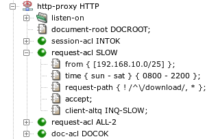
The HTTP communication speed cannot be limited by the packet filter,
because the desired conditions for queue selection cannot be expressed in
a filter-acl. Hence, we utilize the possibility to specify
a queue in an ACL of a proxy. In Figure 5.86, “Traffic shaping by proxy ACLs”,
request-acl SLOW matches response data returned by Web
servers for requests issued by clients from the subnet 192.168.10.0/25 each day between
8 and 22 hours. Requests with URI path beginning with the string
/download are exempted from traffic shaping. The matching
response data are queued to client-altq INQ-SLOW as they
are sent to the client by the proxy. If we wanted to limit speed of request
data sent by the client, we would use
server-altq OUTQ-SLOW to queue data when they are sent
to the server by the proxy.
There are several ways how to check that traffic shaping is working
correctly. The command pfctl -s queue -v
executed on the shell command line displays the numbers of packets and bytes
passed via individual queues. The proxy online monitoring, described in Section 6.3, “Monitoring of Active Sessions”, reports the current data transmission rates of all active
sessions. The amount of transferred data and the session duration are reported in a
SESSION-END log message for each terminated session.
Kernun UTM supports creation of virtual private networks using OpenVPN. There
can be any number of the virtual networks configured for a single Kernun UTM
system. Each instance is described in its own openvpn
section of the configuration. When applied to the system,
each instance is displayed in the GKAT as a running application.
Each OpenVPN instance uses an interface, TUN or
TAP. The interface, referenced from the openvpn section
by item openvpn.interface, is dedicated to
the particular openvpn instance. When applied to the system, the interface
is displayed separately from the openvpn application, among other
interfaces in the system. Data that comes from the virtual network and
is sent to the virtual network appears at this interface (or is sent to
it). An example of GKAT window with OpenVPN-related components is depicted
in Figure 5.87, “OpenVPN components in a GKAT window”. There is an OpenVPN instance
OPENVPN-RAS and its related interface
OPENVPN-RAS-IF, which serves as the Remote Access Server
(RAS). Another OpenVPN instance is OVPN-BRANCH, which
provides a virtual link to branch.
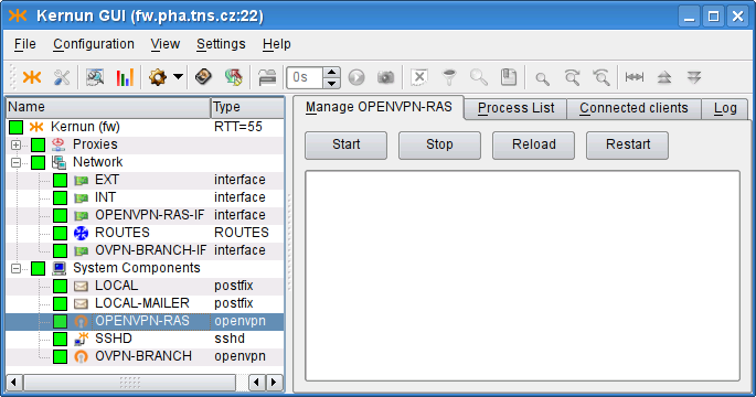
Examples of the OpenVPN configuration described here are available
in the sample configuration file
/usr/local/kernun/conf/samples/cml/openvpn.cml.
Remote Access Server is an OpenVPN server that allows creation of Virtual Private Network between clients outside the company (Road Warriors) and the company server. These clients, if properly configured, can access internal resources (servers) that are not accessible via the external interface, as if the clients were located inside the company. In this chapter we will configure OpenVPN Remote Access Server to create the virtual network using a wizard, which can be started using . Ways of granting road warriors access to the internal resources are outlined in Section 22.3, “Accessing the virtual network”.
OpenVPN creates a virtual device, and all the VPN communication goes
through this device and is encrypted/decrypted. After choosing the section
names, we need to decide whether to use the tap, or the
tun
interface. TAP works with Ethernet frames and is used to create a
network bridge, while TUN works with IP packets and is used with
routing. We opt for tun and choose an unused device number, 1 in
our case. Then we need to define the virtual network, in which the server
and clients will communicate. We choose [10.8.0.1/24], thus
assigning the server (us) IP address 10.8.0.1. It is very important to
choose a network address that does not collide with any other network, from
which the client would connect. Finally, we specify the virtual IP address
that will be assigned to the other point of the tunnel; we choose
10.8.0.2. The result is shown in Figure 5.88, “RAS: Virtual network settings”.
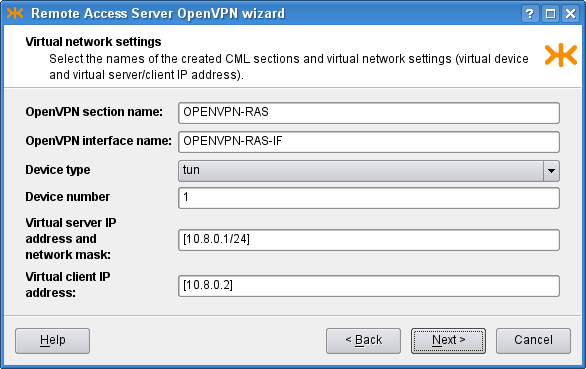
On the second page we choose the IP address to bind the openvpn server
to. We choose the option any, which listens on all the interfaces
in the system. The other option, addr, allows the user to
specify a single address for binding. We leave the port option set to the
default value, 1194. OpenVPN is typically used with the
UDP protocol. The result is shown in
Figure 5.89, “RAS: Physical network settings”.
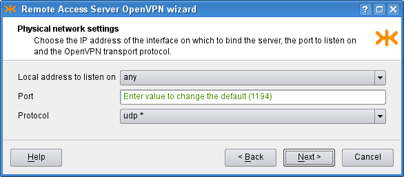
OpenVPN is used to create secure connection, and therefore needs to
authenticate the connected clients. We need to define a certificate of the
used certification authority, a server certificate and a key signed by this
authority. As we have these certificates in separate files in the
PEM format, we check the second radio button
on the third page of the wizard and create new shared files by clicking the
![]() icon and selecting the option. A dialog depicted in Figure 5.90, “Shared file creation dialog” opens.
There we set the
icon and selecting the option. A dialog depicted in Figure 5.90, “Shared file creation dialog” opens.
There we set the shared-file name and upload a local
certificate file to Kernun UTM. We do not have any certificate revocation list
(a list of compromised client certificates) and we leave the
Diffie Hellman parameters unchanged (the parameters are already distributed
with Kernun UTM and this parameter is not a secret). Finally, the third page
should look like Figure 5.91, “RAS: Authentication settings”.
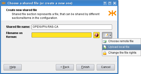
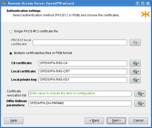
On the Client settings page we can control the interaction between the
clients and the server, and among clients. We allow clients to
connect among each other and we specify that we accept only connections from
clients configured on the clients. In the bottom part of the window, we
configure two clients, client1 and client2,
and set the IP addresses to be pushed to them. If we do not specify the IP
addresses, they will be assigned automatically. On the first page, we chose
the tun interface, which creates a
/30 network for each client. In each of these networks,
the 0. address is the network address, the 3. address is the broadcast
address and the middle two remain for the server and client. Therefore, we need to
choose one of these middle two IP addresses for the clients, for example
[10.8.0.10] and [10.8.0.14]. The tap
interface does not create such networks, so if we chose it, we would be
able to choose the IP addresses freely from the specified [10.8.0.0/24]
network (except the network, broadcast and the server ones). In the middle
part of the page there are several IP addresses that can be pushed to each
connected client; we choose to push only the default gateway. The resulting
page is depicted in Figure 5.92, “RAS: Client settings”.
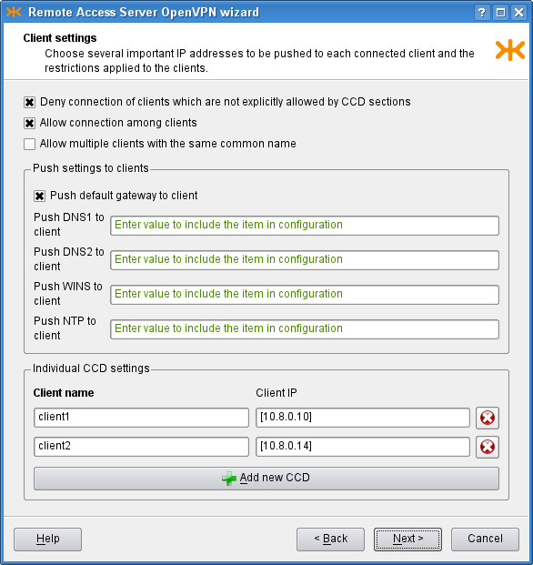
Finally, on the Miscellaneous page, we can modify the predefined
timeouts, encryption algorithm, compression and log level. In our
example, however, we leave the default values of these parameters and proceed
to the recapitulation, where we can check the selected choices and either finish
the wizard, or return back
to previous pages and modify them. The resulting OpenVPN RAS along with the
OpenVPN Net2Net configuration can be found in the sample file
openvpn.cml in the
/usr/local/kernun/conf/samples/cml directory. The
resulting configuration is shown in Figure 5.93, “RAS OpenVPN wizard: The resulting configuration”
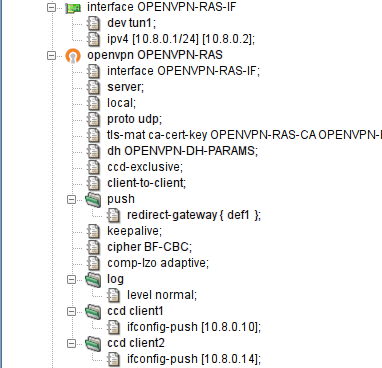
In order to create a configuration for the client to make it able to connect to the created RAS server, it is first necessary to create the client certificate and key with the certification authority that is used for the OpenVPN, and get the certificate of the authority and the two created files to the client computer. Then we create the configuration file of the openvpn program and start the openvpn daemon with this configuration file on the client. An example of the configuration file:
# we are a client client # name of the device on the client computer, needs # to be the same type as on the server (tun/tap) dev tun1 # communicaton protocol proto udp # remote access server hostname (or IP address) and port remote kernun.kernun.com 1194 # certificate of the Certification Authority (the same # as on the server ca /etc/openvpn/keys/ca.crt # client certificate file and key signed by the CA cert /etc/openvpn/keys/lj.crt key /etc/openvpn/keys/lj.key # additional options resolv-retry infinite nobind comp-lzo adaptive
OpenVPN can be used to create a secure point-to-point connection either
between two Kernun UTM systems, or between a Kernun UTM system and another system. A
virtual point-to-point tunnel interface tun is created in the
system.
This chapter covers the procedure of configuring the point-to-point connection using the Openvpn Network to Network wizard ().
Suppose we want to establish an OpenVPN connection between systems fw and branch. Let us show the configuration for fw; the other side is to be configured complementarily.
We start with describing the parameters of the virtual network to be
created (see Figure 5.94, “Net-to-Net OpenVPN wizard: Virtual network settings page”). We choose a name for the
openvpn section (OVPN-BRANCH) and for
the respective interface (OVPN-BRANCH-IF),
the ID of the tun interface (5), and the
IP addresses to be assigned to the virtual ends ([192.168.155.1/32] and [192.168.155.2]). Note that the local end is
specified with the /32 mask.
Important
The IP addresses of the virtual endpoints can be chosen almost arbitrarily. However, the address should be chosen so that it does not collide with any of the used/accessible networks.
Important
The TUN interface should be used in the point-to-point mode. In this mode, the mask /32 should be used for the local peer virtual address, which denotes that no subnet should be routed into this interface by default. If a different mask was specified, an implicit route for the given network would be created.
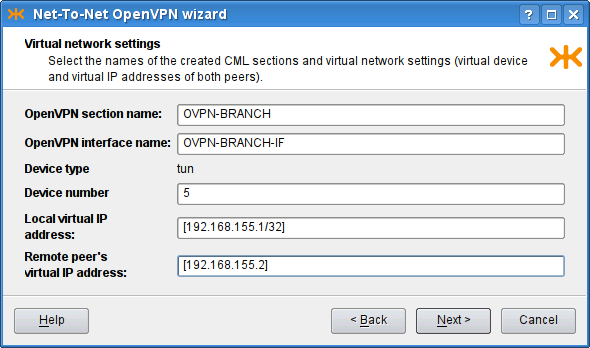
On the following page of the wizard (see Figure 5.95, “Net-To-Net OpenVPN wizard: Physical network settings page”)
we set the physical network parameters: the protocol to be used
(UDP), the local address and port the OpenVPN server would
listen on (the external IP address ^system.EXT.ipv4.host and port
2194). We also set the remote host to be
branch.tns.cz, port
1194. Finally, we add the network [192.168.25.0/24] to be routed through this
tunnel[42].
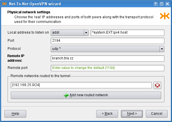
The following page of the wizard (see Figure 5.96, “Net-To-Net OpenVPN wizard: Authentication settings page”) is used to specify authentication options. We can choose between the TLS mode[43] and the Preshared static key file[44]. We have chosen to use the TLS-Server mode and provided the CA certificate, the Local certificate and the Local private key. Finally, on the last page, we can adjust miscellaneous settings; we keep the default values.
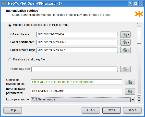
The resulting configuration is depicted in Figure 5.97, “Net-To-Net OpenVPN wizard: The resulting configuration”. We have shown the configuration for one of the peers; the complementary configuration should be used on the other.
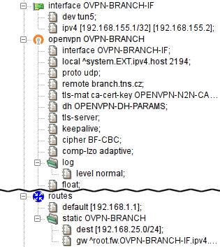
We have shown how to create virtual connections between peers (1:N in Section 22.1, “Remote Access Server” or 1:1 in Section 22.2, “Network to Network”). If the network traffic is supposed to “go through” the Kernun UTM system, it must be explicitly configured so. There are several ways to achieve this.
One way to set the policy for the network traffic that comes through the virtual network is to provide a proxy for each service that should be accessible from the other side of the virtual network. The proxy would be configured like any other regular proxy.
Another method of interconnecting two (or more) networks is to arrange ip-forwarding among them. See Section 1.4, “Selective Packet Forwarding” for more details.
Kernun supports IPsec in the transport and tunnel modes, using the ESP protocol. In the transport mode, Kernun requires a tunnel (GIF or GRE) interface and uses IPsec to encrypt the encapsulated traffic passed via this interface. In the tunnel mode, IPsec encrypts traffic between the specified networks. IPsec in Kernun consists of several parts, represented by components in GKAT. IPsec packets are handled by the operating system kernel according to the SPD (Security Policy Database) and SAD (Security Association Database). The SPD entries for individual IPsec tunnels are controlled by the ipsec Kernun components. Security associations are created by ISAMKP daemon Racoon, presented also as a separate component.
A GKAT window with IPsec-related components is depicted
in Figure 5.98, “IPsec components in a GKAT window”. There is a GIF tunnel network interface
called GIF-IPSEC, which is used by the IPsec tunnel represented by
the TRANSPORT component. Another IPsec tunnel, the
TUNNEL component, uses IPsec in the tunnel mode (without
a related tunnel interface). The RACOON component is the ISAKMP
daemon.
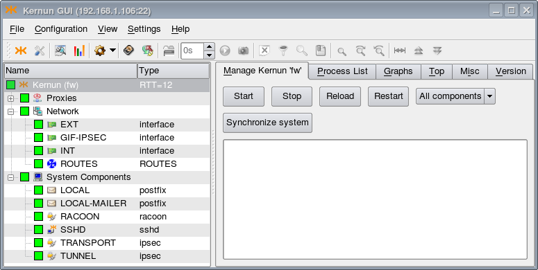
The examples of IPsec configuration described here are available in the sample
configuration file
/usr/local/kernun/conf/samples/cml/ipsec.cml.
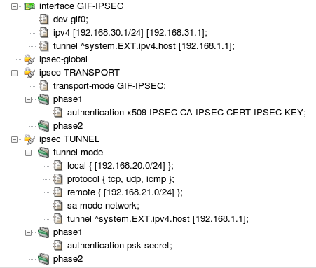
The resulting IPSec configuration in both modes is shown in Figure 5.99, “IPsec configuration”. When applied, IPsec-related components
GIF-IPSEC, RACOON,
TRANSPORT, and TUNNEL will be created
and become visible in GKAT (see Figure 5.98, “IPsec components in a GKAT window”). For
IPsec in the transport mode, the configuration contains the tunnel interface
GIF-IPSEC. Its configuration section defines the
interface device name, local and remote logical IP addresses, and the
tunnel addresses (the physical IP addresses used for the encapsulation of
tunneled packets). Section ipsec-global can contain
global parameters of the ISAKMP daemon. There is a section for each IPsec
tunnel. Section ipsec TRANSPORT configures IPsec in
the transport mode for encryption of packets travelling via interface
GIF-IPSEC. The authentication utilizes X.509 certificates.
Other ISAKMP phase 1 and phase 2 parameters have the default
values. Section ipsec TUNNEL sets up IPsec in the
tunnel mode. It is not related to any network interface, hence the
networking parameters — local, remote, and tunnel (physical)
addresses, set of protocols handled by IPsec, and security association
mode — are defined inside the ipsec section.
A pre-shared secret key for authentication is specified. Again, the remaining
ISAKMP parameters have the default values.
To reduce the risk of system failure, Kernun UTM allows to build hot stand-by clusters. As the name suggests, apart from the main Kernun UTM system, there is a copy of it, usually equipped with the same features and configuration, ready to step up and start handling the communication automatically if the main node fails.
Important
When running Kernun in the virtual environment (like VMWare, VirtualBox, Hyper-V etc.), the network adapter to be used for the shared IP address MUST be set the Promiscusous Mode.
VirtualBox: Settings -> Network -> Adapter -> Promiscuous Mode: Allow All
Microsoft Hyper-V: Settings -> Network Adapter -> Advanced Settings -> Enable Spoofing of MAC Addresses
VMWare vSphere: ESXi/ESX Host -> Configuration -> Hardware -> Networking -> Properties -> Edit -> Security tab -> Promiscuous mode -> Accept
Citrix Xen 6.5: no special settings needed
In this chapter, we assign the systems labels “node A” and
“node B”. The system that is currently in charge of traffic control is
called master node within the cluster, while its idle peer is
backup node. Under normal circumstances, node A is master
and node B is backup. Naturally, both nodes must be connected to the same
networks, so we assume that the number of active network interfaces on both
nodes is the same. Figure 5.100, “Simple cluster with two nodes and two networks” illustrates a typical cluster
topology consisting of nodes fw-a and fw-b, securing communication between an
internal network (let us call it INT) and the external
network—Internet (EXT).
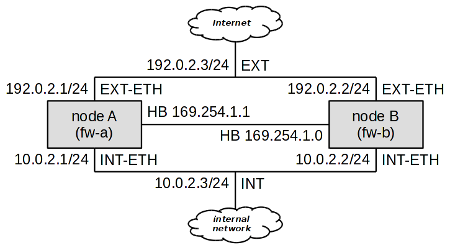
As we can see, at least three IP addresses are needed for each network to build
a two-node cluster; each node must have its own IP address, and a shared cluster IP
address must be present. For example, in the network INT, node A has got IP
address 10.0.2.1, node B
10.0.2.2, and the shared cluster
address is 10.0.2.3. In the
external network, node A has been assigned the address 192.0.2.1, node B 192.0.2.2, and the shared address is
192.0.2.3.
There also needs to be a special “heart-beat” link (simple ethernet
connection between nodes) for cluster nodes to see each other. A dedicated deamon
pikemon listens on this interface on both nodes and informs
each other of their state and priority. In this example node A has address
169.254.1.1 and node B has address
169.254.1.0.
Important
The pikemon daemon determines his peer address
on heart-beat network by performing XOR on the last bit of his own IP address.
If unsure which addresses to choose, use addresses from this sample configuration.
It would be tedious to keep configurations of both cluster members
up-to-date. To simplify cluster administration, Kernun UTM makes it possible to specify
multiple system sections in the same configuration file. Normally,
such a configuration file resides one of the nodes, say node A in our example.
When the configuration is to be applied, we need to recognize which of the systems
is local and which is remote, and how to reach the remote system. The
apply-host configuration directive serves this purpose. If
not present, the system configuration is applied locally. Otherwise, its parameter
specifies the host name or address and the SSH daemon's port the system
configuration should be applied to. Figure 5.101, “apply-host is used to distinguish
the local system from the remote one” illustrates the use of the apply-host
option.
The existence of two system configurations in the same file would not relieve us of the burden of keeping both system configurations up-to-date. We shall use a section variable (as defined in Section 1, “Configuration Language”) to simplify cluster administration further.
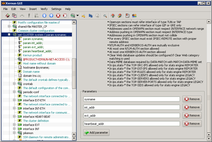
First, let us create a system variable called CLUSTER.
Figure 5.102, “Definition of system variable CLUSTER” shows its definition. Apart from its
name, there are four parameters that distinguish individual nodes of the
cluster:
sysname— The name of the system.int_addr— The internal IP address of the system (not the shared one).ext_addr— The external IP address of the system (not the shared one).heartbeat_addr— The heart-beat IP address of the system.
The system variable CLUSTER includes what both nodes have in common,
which is practically the whole of their configuration. They differ only in
the four parameters described above, and in the way the configuration is applied.
The parameters are used on their appropriate places within the CLUSTER
definition, as shown in Figure 5.103, “Usage of parameters inside CLUSTER definition”. For instance, the
$sysname parameter is used within the hostname
directive to define the system's host name (the row marked
). The real internal address, specified
in parameter $int_addr, is used inside the interface
INT-ETH definition (row $ext_addr is used to specify
the IP address of interface EXT-ETH (row
) and $heartbeat_addr is used
for interface HEART-BEAT (row
).
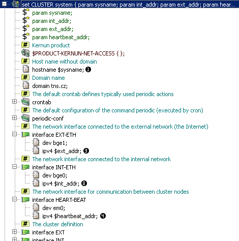
The section variable CLUSTER defined above needs to
be referenced to use its contents to define a real Kernun UTM system. Upon referencing the
variable, its parameter values must be filled in. In our example, we use the
variable CLUSTER twice to define two nodes: system fw-a and
system fw-b, as depicted in Figure 5.104, “Use of variable CLUSTER to define two nodes”.
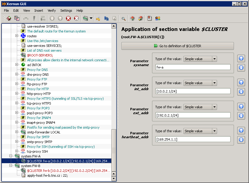
Cluster functionality, as described above, ensures that if node
A fails, node B takes over automatically, causing minimal communication
blackout (a few seconds at the most). However, if the failure is related only
to one of the network interfaces (i.e. switch port fault, cable or
network interface failure), say on interface EXT of node A,
we would end up with node A still being master for network
INT, but node B being master for network EXT.
This is incorrect, as packets going from internal clients out would go through node
A (master for the internal network), which is not properly connected to the external
network.
To handle such conditions, Kernun UTM makes it possible to tie cluster interfaces together. A self-detector monitors the state of its interfaces by pinging other hosts on all relevant networks. By pinging a remote host, Kernun UTM makes sure that the network interface is working properly, including cabling and switch port.
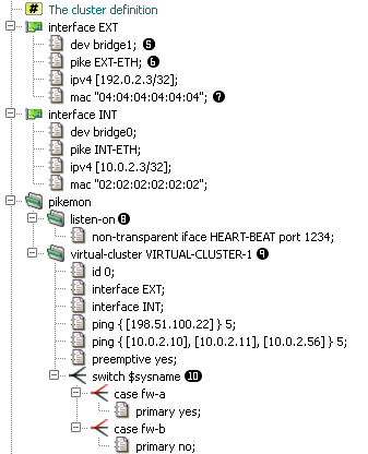
Shared IP addresses (alias “virtual ip addresses” or
“cluster addresses”) are not bound to any physical network interface,
instead they are assigned to a virtual bridge interface
(row pike item (row
), binds particular virtual interface to
a physical one. As the virual IP can migrate from one node of cluster to another,
it is necessary for both nodes to advertise same MAC address for this IP,
as defined in mac item (row
Important
For the shared IP address to migrate properly, it is necessary
on some switched to allow one MAC address to be present on multiple switch ports.
On Cisco switches, this requires setting the port-security
option off for those ports.
The pikemon section defines one or more virtual clusters
and a listen socket for it's daemon to listen on (row
). You can choose any free port on the
HEART-BEAT interface.
The virtual-cluster section (row
) defines a logical group of virtual IP
addresses and their properties. In this example we want the EXT and INT interface
to be part of one virtual cluster, so that in case of disruption of communication
of one node with internal network, the node also give up it's master role on
EXT interface. Such disruption is detected by timeout of ping request for defined
group of hosts. When more addresses are defined in one ping
item, all of these addresses must fail to respond to ping request for a cluster
node to lower it's priority. In this example, unavailability of
198.51.100.22 will result in a node
loosing master role, on the contrary unavailability of
10.0.2.11 would not, because all of
the 3 hosts in the second ping item must be down.
Tip
When choosing hosts for cluster monitors, take into consideration that the remote host should be always up. The best choice is a router or switch, network servers being the next best option.
Next, we define a switch command (row
) which enables us to use different
configuration for each node (fw-a and fw-b). We set node A (fw-a) to by primary
node of this sample cluster.
In the virual-cluster section, it is possible to influence
another aspect of cluster behavior. Suppose node A had a failure, and node
B has become master. Once node A is recovered, node B could either remain
the master node, or hand the master status back to node A. By default, the former
is true, but we may force the latter by adding the preemptive
directive.
Tip
It is highly recommended to use the preemptive option in
all cluster configurations.
Important
In cluster configuration, both transparent and non-transparent
proxies need to listen on the virtual bridge interface
(INT and EXT interfaces in this sample). The same applies to all packet-filter
rules except for nat-acls which must be set on physical
network interface (INT-ETH or EXT-ETH). It is also suitable for some services
to listen on physical interface addresses. for example SSH daemon should listen
on physical IP address, so it would be possible to connect to both nodes. See
/usr/local/kernun/conf/samples/cml/cluster.cml for more
examples.
In order to control more systems from a single GUI, set up the following daemons: icamd(8) and icasd(8). The master (icamd) allows the slaves (icasd) to be controlled. The situation is shown in Figure 5.106, “Multiple systems can be controlled using icamd / icasd daemons”: the GUI is connected to the system pha (bold font in the tree view). The systems pha-b and bno can be controlled, because they are connected to the system pha via icamd/icasd.
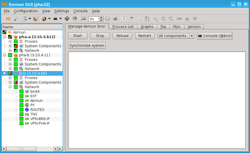
There is a simple way to setup icamd/icasd daemons for the cluster of
two systems. Both daemons are configured by the single item
SYSTEM.ica-auto. See Figure 5.107, “Simplified icamd/icasd configuration using item
ica-auto”. The rsa
key pair is provided for mutual authentication. The communication port
is provided.
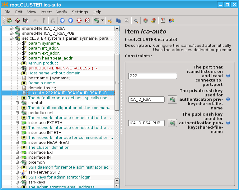
The more complicated topologies are described in the configuration explicitly by the configuration of the icamd/icasd daemons, as shown in Figure 5.108, “Full icamd/icasd configuration”: The configuration for two systems (pha-a and pha-b) is provided. They can control each other. Morover, there is a third system (bno), which is also connected via icamd/icasd (but system bno does not share the configuration with pha-a and pha-b). The configuration is symetric for pha-a and pha-b. Both define the icamd (for being able to control the other systems), and icasd (for being controlled by the other systems). The ssh-key pair is provided for each system's icamd and each system's icasd (6 key pairs in total: 3 key pairs for icamd daemons, 3 key pairs for icasd daemons). The listen port is provided for the icamd daemons. The address and port is provided for each icasd's master section.
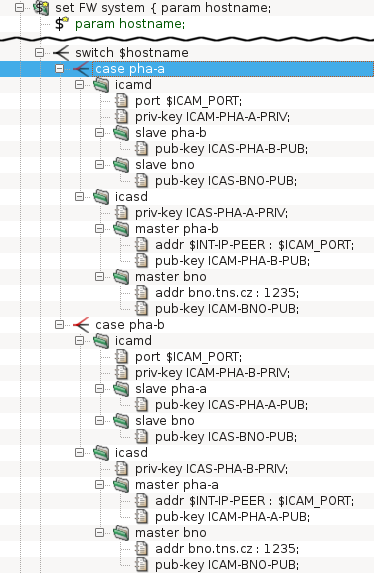
Should the configuration be shared among several Kernun systems (for
example in the clusters (Section 24, “High Availability Clusters”) or KBA (Section 25, “Kernun Branch Access”), the SYSTEM.config-sync configuration
item should be used. This item implies that the configuration is
automatically synchronized to the remote system, whe being remotely applied.
Kernun Branch Access is a device with the primary task to provide a remote branch of a company with a secure connection to a central Kernun UTM. In addition, Kernun Branch Access provides another security features for the perimeter of the network such as network packet filtering and VPN. Optionally, the device can also serve as a Remote Access Server for VPN. Kernun Branch Access is designed to be used together with Kernun UTM and should not be used separately.
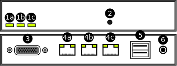
Status LEDs (1a, 1b, 1c) — Three LEDs, which are intended to indicate the status of some key functions of the device.
Button — Serves for confirming configuration application and starting the Remote Help Service. In order to press the button, use a paperclip or a similar tool.
A serial console connector
Ethernet ports (4a, 4b, 4c) — Kernun Branch Access is equipped with three Ethernet ports. The ports serve for connecting the device to LAN and WAN.
USB ports — Kernun Branch Access is equipped with two USB 2.0 ports.
Power supply input
In order to power Kernun Branch Access on and connect it to the network properly, the following steps should be taken:
Plug-in a power supply connector to the power supply input (6)
Plug-in an Ethernet cable connected to LAN into an Ethernet port (4b)
Plug-in an Ethernet cable connected to WAN into an Ethernet port (4a)
In order to install Kernun Branch Access, you need a Kernun Branch Access installation medium[46]. Since the device is equipped with serial console output only, it is also necessary to modify installation process according to the guide described in Section 5.5, “Enabling Serial Console Output”. After this modification, the operating system will output to serial console while booting and the installation will be similar to the installation of Kernun UTM from standalone installer described in Section 5.1, “Standalone Installer”.
Configuration of Kernun Branch Access can be performed in two different ways:
Initial configuration using a USB flash drive, which is typically applied when Kernun Branch Access is configured for the first time.
Standard configuration applied remotely from a central Kernun UTM.
Both of the configuration options will be described in the following sections.
Kernun Branch Access is usually supplied in the form of a compact device configured to default factory settings. Since the supplied device has no active network connection available yet, no remote configuration technique similar to the one described in Section 24, “High Availability Clusters” can be used. In order to configure the Kernun Branch Access for the first time, it is necessary to apply the configuration using a USB flash drive.
The procedure consists of two steps. Firstly, the configuration for Kernun Branch Access is defined on the central Kernun UTM and then, using a series of commands, it is exported into a special configuration file. Secondly, the exported file is copied to an arbitrary USB flash disk and the disk inserted into one of USB ports on the device. The whole procedure is described in details in the following paragraphs:
Exporting a configuration file from a central Kernun UTM
Defining configuration for Kernun Branch Access on central Kernun UTM
The configuration is defined as a single
systemsection (see Section 2.2, “System” for more details onsystemconfiguration basics).Generating and exporting the
systemconfiguration into a file using the kat(8) command line toolThe tool can be launched either directly using an SSH remote access to the terminal of the central Kernun UTM or by pressing the GUI Console icon (marked as number 6 in Figure 3.14, “Main window toolbar buttons, listed together with the corresponding menu items, and sometimes keyboard shortcuts:”).
KAT@central-utm>cmlCMLR-710-K File '/usr/local/kernun/conf/kernun.cml' loadedCML>/generate... CKGB-710-N ---- Preparing files for system 'kba-office'... ... CKGB-719-N ---- System 'kba-office' successfully generatedCML>/quitCMLI-709-N CLI interactive mode closedKAT@central-utm>export kba-officeCMLK-821-N [root] Exporting 'SYSTEM-kba-office' configuration Exporting configuration to /root/SYSTEM-kba-office.tar tar: Removing leading '/' from member namesKAT@central-utm>quitAfter applying the
exportfunction, the configuration file namedSYSTEM-kba-office.tarshould be exported to the home directory of the user who launched the command.Transporting the generated file to the administrator manipulating the Kernun Branch Access.
In case the administrator who generated the configuration file does not have physical access to Kernun Branch Access, the file must be transported to the administrator manipulating the device itself. It might, for example, be sent by an e-mail.
Preparing and inserting the configuration USB flash drive into Kernun Branch Access
Once the configuration file is exported and delivered to the administrator having physical access to Kernun Branch Access, the following steps should be taken:
Copy the configuration file (e.g.
SYSTEM-kba-office.tar) to the root directory of an arbitrary USB flash driveInsert the USB flash drive into one of USB ports of Kernun Branch Access (5)
After inserting, the device will beep once shortly and then wait 30 seconds for confirming the application by pressing the button (2). If the timeout runs out, the device will beep nine times shortly and no configuration will be applied. In such case, the USB flash drive must be reinserted and confirmed.
Confirm the configuration by pressing the button (2) with a paperclip or a similar tool
If the button is pressed, the device beeps three times shortly and automatically starts the configuration process. If the process succeeds, the device beeps once longly, otherwise it beeps three times longly.
After successful configuration, the network connection with central Kernun UTM should be established and Kernun Branch Access can be further configured remotely using the process described in the following section.
Note
The way of configuration using a USB flash drive is primarily intended for setting the very first configuration, when Kernun Branch Access has no network connection with the central Kernun UTM available. However, it may be reused arbitrarily when needed in the future.
If the initial configuration using a USB flash drive has already been
successfully applied, Kernun Branch Access can be further configured remotely.
The desired configuration can be prepared as a standalone system on the central Kernun UTM
with apply-host configuration directive applied. Instructions for
proper setting and applying the apply-host directive can be found at
Section 24, “High Availability Clusters”.
Kernun Branch Access is intended to operate without a monitor or any kind of a administrator's console. Therefore, it has only limited possibilities to indicate its current state or communicate with users and administrators. Three build-in LEDs serve for basic diagnostics of the key functions of Kernun Branch Access. In this section the meaning and the purpose of each LED will be described. It will also be explained how the Remote Help Service can be started and what its purpose is. Finally, steps to be taken in order to reset the device back into the default factory settings will be described.
Kernun Branch Access is equipped with three LEDs, which are intended to indicate the status of some key functions of the device. The meaning of each LED is as follows:
The left LED (1a)
Indicates whether Kernun Branch Access is powered on. If so, the diode should light continuously without interruptions.
The middle LED (1b)
Indicates a status of all configured KBA components after a boot of the system. After the system boots, the diode starts to blink, which indicates that the KBA components are being verified. If all the components are successfully started, Kernun Branch Access beeps once long and the diode starts to light continuously. If not, Kernun Branch Access beeps three times long and the diode turns off.
The right LED (1c)
Serves for indicating a status of the Remote Help Service. When the service is started by pressing a Remote Help Service button (see Section 25.4.2, “Remote Help Service Button”), the diode will blink quickly until the service is ready (the process should not last longer then 60 seconds). If the service was started successfully, the diode should begin to light continuously, if not, it turns off. Similarly, when the service shuts down, the diode begins to blink until the process is finished and then it turns off.
The Remote Help Service is a service allowing the technicians of the manufacturer of Kernun UTM temporary access to Kernun Branch Access in order to diagnose and maintain it remotely. The service can be both started and stopped by pressing the button located on the front side of the device. The entire starting procedure consists of the following steps:
Press the button (2) with a paperclip or a similar tool for 5 seconds.
The right LED (1c) starts to blink.
When the right LED begins to light continuously, the Remote Help Service was started successfully. The diode will light all the time the service will be active.
Kernun UTM supports IPv6 since version 3.5. An example of an IPv6-enabled
configuration can be found in the sample configuration file
/usr/local/kernun/conf/samples/cml/ipv6.cml. It is
a dual-stack configuration with IPv4 and IPv6 enabled both in the internal and
the external network. Clients from the internal network can access HTTP
and SSH servers in the external network. For a transparent (HTTP or SSH)
proxy, the target server IP address is taken from the destination address of
the client's connection. Hence the same IP version is used by the client and
the server. In the case of the non-transparent HTTP proxy, the target server
name is passed by the client to the proxy in the request URI. The proxy
resolves the name and establishes connection to the server. Hence an IPv4
client can access an IPv6 server and vice versa.
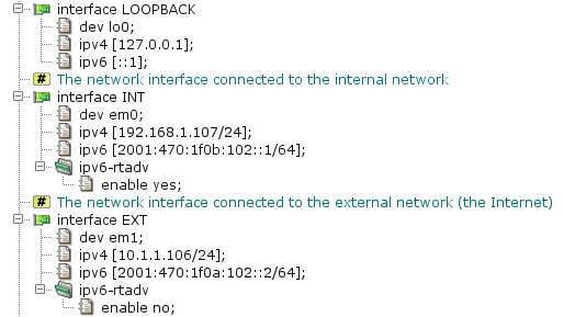
The configuration of network interfaces is depicted in Figure 5.110, “IPv6 interfaces”. There are three interfaces:
LOOPBACK is the standard system loopback interface;
INT and EXT are the internal and the
external Ethernet interfaces, respectively. IPv6 support in Kernun UTM is enabled
if at least one IPv6 address is assigned to any network interface in the
configuration[47]. IPv6 addresses are defined by the
ipv6 item. It is also possible to specify IPv6 aliases by the
alias section. By default, Kernun UTM operates as an IPv6 router,
but it does not send router advertisements.
Router advertisements can be turned on and their parameters can be set for an
interface in the ipv6-rtadv section.
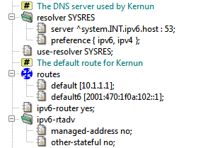
Some global IPv6-related networking parameters are depicted in Figure 5.111, “IPv6 networking parameters”. The resolver section defines
the name server address[48].
A single domain name can be resolved to an IPv4 or an IPv6 address. The
preference item selects, which resolved addresses will be
used. There are four possibilities: use IPv4 and ignore IPv6, use IPv6 and
ignore IPv4, use both and prefer IPv4, or use both and prefer IPv6. The last
choice is used in the sample configuration. The default is to prefer
IPv4. The routes section defines the default IPv4 and IPv6
routes. It is also possible to add static routes to IPv4 and IPv6 networks by
the static item. The ipv6-router item
enables or disables forwarding of IPv6 packets. IPv6 forwarding is enabled by
default, so this item can be omitted. The ipv6-rtadv section
defines default values for IPv6 router advertisements. These defaults can be
overriden by an interface.ipv6-rtadv section. In the example
configuration, router advertisements are configured so that they provide
address and default route autoconfiguration and DHCPv6 is not used.
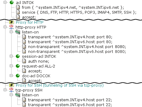
The sample IPv6 configuration contains HTTP and TCP proxies, depicted in
Figure 5.112, “Proxies with IPv6 support”. Their configurations are similar to
IPv4-only proxies. The only differences are IPv6 addresses in the listen-on items and in acl INTOK.
IPv6 addresses can be used in place of IPv4 addresses in many other
places in the Kernun UTM configuration. It is possible to use other proxies for
IPv6 communication, as well as define IPv6 packet filter rules and IPv6 IPsec
VPN connections. We do not show configurations of these components here,
because they are essentially the same as the respective IPv4-only
configurations. DHCPv6 server is configured in the
dhcp6-server section, in a way similar to DHCPv4 server in
the dhcp-server section. Fixed IPv6 addresses and AAAA DNS
records can be defined by entries in the hosts-table
section.
There are also some important differences and limitations of
IPv6. Destination IPv6 address must not be set for a point-to-point network
interface (TUN, GIF, GRE). The GRE network interface type does not support
IPv6 tunnel addresses. OpenVPN cannot use IPv6 transport. The
mac value of an IPv6 entry of the
hosts-table is interpreted as the host's DUID.
The idea behind honeypot is to provide a resource valuable to attacker and by monitoring attackers behaviour counteract his attempts to unauthorized use of information systems. In an example scenario, we dedicate one public IP adress as "honeypot" address. This IP address should not be referred in any DNS record and must not by referred in any web site or elsewhere, so that we can assume only attackers automatically scanning all IPs attempts to connect to this honeypot address. Automatic scans function generally in two modes. Some scanners send TCP SYN packets to a range of IP addresses, immediately forgeting about it a detecting open ports by simply monitoring incomming TCP SYN+ACK packets (see http://en.wikipedia.org/wiki/Transmission_Control_Protocol#Connection_establishment for explanation of TCP connection establishment). Other scanners attempts to complete TCP handshake and eventually continue the scan on application level. Kernun UTM logs all attempts to connect to honeypot and blacklists all IP addresses that completed TCP handshake. Once on blacklist, any traffic (any protocol) on any network interface (not just honeypot address) from that IP address is blocked.
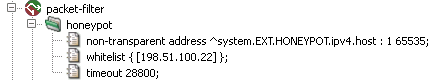
The section honeypot is part of the
packet-filter. The item non-transparent
defines on which address and ports should we listen for attacker's connections.
In this example it's all available ports. In whitelist
we defined IP address of our monitoring server which should not be placed
on blacklist even if it connects to honeypot address. Finally
timeout defines time period (in seconds) for which IP address
should remain in blacklist, after it became silent, i.e. after there is no
new connection from that IP address on any of our network interfaces.
[24] The packet filter is based on BSD pf.
[25] The ESP and AH protocols are both a part of the IPsec protocol family.
[26] The internal network is taken from the definition
of interface INT.
[27] Currently, Kernun UTM appliance does not allow for optional hardware reference clock delivery, but this is subject to future changes.
[28] Another standard use of the UDP proxy is forwarding the OpenVPN protocol via Kernun UTM.
[29] Kernun UTM refers to the HTTP-FTP cooperation protocol as HTFTP.
[30] This happens in the case of the first request or a wrong name or password entered by the user.
[31] Trusts are needed because the Kernun system authenticates itself in only one Kerberos realm, but it must be able to accept authentication from other domains and also to authenticate itself to LDAP servers in other domains.
[32] The client should choose the strongest implemented authentication scheme, in this case NTLM.
[33] Kernun uses Samba for communication related to the NTLM authentication between a proxy and the Active Directory.
[34] usually in the internal network or in the demilitarized zone
[35] implemented only for authentication method RADIUS
[36] Keep either
SMTP, or SMTP-2
hidden—they are not designed to work in
parallel.
[37] Note that
the file referenced in the replace item must exist in
the system (if it does not exist, it must be created).
[38] In fact, the score returned by SpamAssassin is multiplied by 1000, because the Kernun UTM configuration does not handle floats. This feature also allows the future compatibility with other antispam software.
[39] This rule might replace attributes other than href
(such as src or action) with a href, but such a change
will not “damage” the document more than simple deletion of the attribute would.
[40] The request will be sent to the destination server and its response will be returned to the client.
[41] Unlike INQ-SLOW,
this queue cannot borrow bandwidth.
[42] Given that this is the network that is used in branch.
[43] Either a single PKCS12 or the tuple of PEM files (certification authority's certificate, local peer's certificate and the local peer's private key) should be specified. In this case, one peer must be specified to be the TLS server, and the second to be TLS client.
[44] The same secret key is supposed to be used for both peers. It can be generated from the “Create new shared key” dialog.
[45]
The interface is created automatically when used in an interface.dev
item.
[46] You can use dd on Linux / BSD or
ImageWriter
on Windows to copy the USB flash drive image to the device.
[47] Note that in addition to explicitly assigned addresses, each interface has a link-local IPv6 address assigned automatically by the operating system.
[48] In this sample configuration, a local caching nameserver chained to the DNS proxy is used.
Table of Contents
- HtmlMatchPasswd.pm — encapsulates the databases of the HTML form value control tool html-match-db(1) for storing two couples of credentials (internal username and password and external username and password). It also keeps the logs of the actions over the particular accounts.
- clear-web-db-update.sh — tool for updating the Clear Web DataBase
- clear-web-db — tool for managing the Clear Web DataBase
- cluster-sync — tool for synchronizing files between cluster members
- diskdb — tool for creating and querying file system content database
- fwpasswd — create and update password authentication files
- grep-debug — tool for selecting messages from Kernun logs
- grep-stats — tool for selecting messages from Kernun logs
- html-match-db — controls databases of HTML form values used by the generic data matching module
- kernun-audit — checks for bugs and new versions of the Kernun software
- license — tool for checking Kernun license file
- log-ts — tool for selecting messages from Kernun logs
- mkblacklist — tool for converting http-proxy blacklists into DB format
- monitor — report current status of Kernun proxies
- ooba-acs — uses Cisco ACS log to update out of band authentication user list
- ooba-samba — uses a Samba server to update the out of band authentication user list
- oobctl — tool for creating and querying file oob database
- printblacklist — tool for converting http-proxy blacklists into textual format
- quarc.sh — mail quarantine control tool
- resolveblacklist — tool for resolving hostnames in http-proxy blacklists
- rrd — system parameter watching
- sum-stats — generates proxy usage statistics from Kernun logs
- switchlog — distribute messages from Kernun log according to message id and proxy name
- triplicator — SMTP Grey-listing Triplet Database Manipulator
Name
HtmlMatchPasswd.pm — encapsulates the databases of the HTML form value control tool html-match-db(1) for storing two couples of credentials (internal username and password and external username and password). It also keeps the logs of the actions over the particular accounts.
Synopsis
HtmlMatchPasswd.pm -f root_dir [-bpSv] [-u iu] [-d log_level] { -a | -C | -l | -L | -r | -R | -s | -n }
Description
Utility HtmlMatchPasswd.pm is used to manage password files (pairs of internal/external usernames/passwords database) used by the data matching and processing module, see also html-match-db(1), data-matching(7). It provides functions for adding, deleting, listing users, setting the password, etc. It provides a perl package interface for accessing the database by other programs (i.e., www user interface for changing the password by the users). While the command-line interface is intended to be used by the administrator, the perl package interface also provides functionality intended for the end users (check the old password before it can be changed, etc).
Two password files are kept: var/passwd.db and var/passwd.
The first one (passwd.db) keeps the database in
the form it is used by the http-proxy (see data-matching(7)). The other file (passwd)
keeps more information (in particular, it stores the unencrypted local
usernames), so it is possible to change credentials, remove the user without knowledge of
the internal password, etc.
The activity of users is logged. Each user's activity is
logged in file log/internal_username. You can view the log using -L.
Options
-aAdd an user. Internal username, internal password, external username and external password are asked to be entered.
-CCheck the consistency of the two databases (see above). Use
-Rto repair inconsistency.-lPrint the list of internal usernames.
-LShow the user log. Use
-uto limit the log to a single user. Without-u, the log of all users is printed.-rRemove a user. Only internal username is asked.
-RChecks the consistency of the two databases (see above). If an inconsistency is found, it is repaired (HASH found only in
passwd.dbis removed from it, HASH found only inpasswdis added intopasswd.db).-sSet the credentials for an existing user. Internal username, new internal password, new external username and new external password are asked.
-nPrint the license limitations: used, free and total.
-fSpecify the root of the HtmlMatchPasswd.pm file infrastructure. Directories
root_dir/varroot_dir/var/logroot_dir/var/lockroot_dir/var/passwdroot_dir/var/passwd.dbroot_dir/var/log/internal_usernamevardirectory is assumed to exist; the remaining ones are created if they do not exist. All of them must be writable for any user that manipulates the databases.-bBatch mode. Does not display prompts when asking questions, etc.
-dSet the log level explicitly. Otherwise, environmental variable LOG_LEVEL is used. Acceptable values: 0–9.
-pWhen asking for password, the terminal ECHO is normally switched off so it is read silently, without being displayed. This can be overriden by specifying
-b.-SWhen asking for the new internal password, its strength is not checked (and even a weak password is accepted).
-uiuWhen displaying the user log (see option
-L), limit it to the particular user.-vMore verbose mode.
Name
clear-web-db-update.sh — tool for updating the Clear Web DataBase
Synopsis
clear-web-db-update.sh [ -w ] [ -x ]
Description
Utility clear-web-db-update.sh updates the Clear Web operational database, which is used by the http-proxy(8) to categorize web pages. It relies on the clear-web-db(1) utility to manipulate the database. It is executed periodically by cron(8) when automatic updates are configured.
Name
clear-web-db — tool for managing the Clear Web DataBase
Synopsis
clear-web-db { -d | -n | -m }
clear-web-db { -o | -u | -s | -S } [db]
clear-web-db -l [-f] [db]
clear-web-db -c [locale]
clear-web-db -a [db] incr
clear-web-db -i [db] db2 incr
Description
Utility clear-web-db can be used to create, modify, and view the Clear Web operational database, which is used by http-proxy(8) to categorize Web pages. It is usually called by program clear-web-db-update.sh (1), which handles automatic periodic updates of the database.
URLs used by program clear-web-db consist of
a server domain name followed by an optional path, including neither the method, nor
the port number. Example: www.tns.cz/index.html is used
instead of http://www.tns.cz:80/index.html.
Options
-oReads the input textual data from the standard input and writes the operational database into file
db.-uReads the input textual data from the standard input and updates the operational database in file
db.-iCreates the incremental update data between the operational databases stored in files
dbanddb2and writes the result into fileincr.-aApplies the incremental updates from
incrto databasedb.-sReads URLs, one per line, from the standard input, searches for them in database
db, and writes corresponding categories to the standard output. Each output line contains the numeric bitmap of categories followed by a space-delimited list of category names.-SReads URLs, one per line, from the standard input, searches for them in database
db, and writes corresponding categories to the standard output along with the part of the URL that was used to determine the categories. Each output line contains the numeric bitmap of categories followed by the matching URL substring.-lLists the contents of database
db. Each line of output contains a hash value, a bitmap of categories, and a list of category names. When listing an incremental update data, records to be deleted are listed as a hash value followed by the character “-”. If option-fis specified, flags are displayed between the hash value and the bitmap of categories. A flags value is an OR-combination of constants: 0x1 = there may be a record with a longer domain name suffix, 0x2 = there may be a record with a longer path prefix, 0x4 = the record contains categories (without it, the record is used only to continue with a longer domain or path according to 0x1 or 0x2), 0x8 = denotes a record to be deleted (in an incremental update only).-dReads URLs, one per line, from the standard input, and writes digests (hash values) to the standard output.
-cWrites all known categories (numbers and names) to the standard output. If the
localeargument is specified, the category name is localized into given locale.-nReads category bitmaps, one per line, from the standard input and writes the corresponding lists of category names to the standard output.
-mReads lists of category names from the standard input and writes the corresponding category bitmaps to the standard output.
Name
cluster-sync — tool for synchronizing files between cluster members
Synopsis
cluster-sync [-n] [-d
debug_level] -c
cfg
Description
This script performs file synchronization between exactly two (cluster) members.
This script is expected to be executed regularly (i.e. from
crontab). It connects to the remote host, looks for changes made on the
watched files and transfers the changes from one host to the other.
If the file is changed on both hosts, it is considered as the conflict.
It is specified in the configuration, which side is prefered in
conflicts (CONFLICT_WINNER) below.
The hosts are expected to be interconnected by
icamd/icasd daemons. See REMOTE_HOST
below.
Options
The values given on the command line have precedence over values given in the configuraiton file.
-cThe configuration file to be used.
-dThe debug level. Default is 6 (LOG_INFO). Increase it for more verbose logging. The script logs to stdout and to /var/log/kernun-debug.
-nPerform a 'dry run'. No sync actions are performed, just log what would be done.
Configuration file
At least REMOTE_HOST and
INCLUDE must be given. If the option can be
specified both in configuration file and on command line, the
command line value takes precedence.
REMOTE_HOST=TARGETThe ssh target to be used when invoking commands on the other host.
Be sure to use the name defined in
/etc/sshd/ssh_config.There are many commands executed on the REMOTE host, so it is necessary for them to be executed quickly. Daemons
icamd/icasdprovide fast connections since it takes advantage of the sshControlPathfeature.INCLUDE="PATH1"[, "PATH2", ...]The list of the included files, directories or patterns. The absolute path is given, and it must be preceeded by symbol '.'.
Example:
INCLUDE="./var/log/kernun-stats.*.bz2", "./data/fake-cert/fake_ca/C*.*"The values must be written in a comma separated list on a single row.
PRECMD="command"The command is executed to determine whether perform the synchronization or not. Use
PRECMDto prevent synchronization when it is not desired. For example when the cluster is degraded.The command can either be a script name or a simple shell script. It is passed to the perl 'system' call.
No
PRECMDis performed by default.MINIMAL_AGE=secondsOnly files that are older that MINIMAL_AGE are taken in account. This should prevent repetitious copying of the files that are being written for longer period (for examples the zipped logs).
Defaults to 0 (the files are synchronized regardless of their age).
LOCK=filenameThe lock file to be locked in order to start the synchronisation. If the lock cannot be (exclusively) locked, the scripts exits immediately.
By default, the lock prevents the script to run more than once in parallel. It can also be used by other programs not to run simultaneously.
CONFLICT_WINNER={LOCAL|REMOTE}Should the conflict appear, this option specifies whos change wins. Defaults to LOCAL.
RM_STALED={0|1}Whether the staled temporary file should be automatically removed. Defaults to 1.
DRY_RUN={0,1}Perform a 'dry run'. No sync actions are performed, just log what would be done.
DEBUG_LEVEL=numThe debug level. Default is 6 (LOG_INFO). Increase it for more verbose logging. The script logs to stdout and to /var/log/kernun-debug.
Name
diskdb — tool for creating and querying file system content database
Synopsis
diskdb cmd [-1CcDFMqrStvx] -d
db [-d db] [-I
filename...] [-i
pattern...] [-E
filename...] [-e
pattern...] [-L
filename...] [-P
filename...] [-R dir] [path...]
Description
Program diskdb manages a database of information about the contents of a file system. The database contains a list of files and directories in the file system. For each file (or directory), the remembered attributes are its name, metadata, size, and optionally checksum (only for regular files, using cryptographic hash SHA256). The metadata include the file type, permissions, owner, group, times (access, modify, change, create), file flags, and ACLs. For symbolic links, the link target is also recorded. The database is in a textual format.
It is possible to select a subset of the whole file system directory in several ways:
One or more
paths can be specified on the command line or read from a file when creating a database. The operation of the program is then limited to subtrees of the file system hierarchy rooted at these paths. If a path is a directory, its whole subtree is processed by default. If the path arguments are omitted, an empty database is created. If at least one path argument or path file is specified for commands other than create, the operation of the program is limited to these paths (either from arguments or from the file), without recursion for paths denoting directories.Option
-1stops at a file system boundary, that is, mount points are not crossed when creating a database.A list of inclusion and exclusion patterns can be defined. Each path encountered when traversing a file system subtree is compared to the list. The first matching pattern controls whether the path will be processed, or ignored. If no pattern matches, the path is processed, unless
-xis used. The pattern can contain shell pattern matching characters, but they behave more like-pathof find(1), that is, slash and dot characters (at a file name beginning) do not have to be matched explicitly.The list of patterns is composed of patterns defined by options
-iand-eand patterns read from files selected by options-Iand-E. The ordering of options defines the ordering of patterns in the list.Inclusion and exclusion patterns work recursively, that is, including/excluding a directory includes/excludes also its contents.
When a database content is displayed in textual form (by commands
list, diff, and
all other database comparison commands), the output is sorted
by paths component-wise. As this is not the same as the lexicographic order,
two such outputs cannot compared by command comm(1) without being sorted by sort(1)
first.
Commands
createCreates a new database by examining the current contents of the file system. This command requires one
-doption.diffCompares a database with the current contents of the file system or two databases, and writes the differences to the standard output. Each line of the output contains a single character followed by a space and the file path. The first character is '
+' for added files (those existing only in the current file system or in the second database), '-' for deleted files (those existing only in the (first) database), '!' for modified files (different in the first database and the file system or the second database), 'd' for files changed from non-directory to directory (directory in the second database and some other file type in the first database), 'f' for files changed from directory to non-directory (directory in the first database and some other file type in the second database). This command requires two-doptions.diffequalLike
diff, but reports (with prefix '=') also files that are equal in both databases.addedLike
diff, but reports only added files, one path per line.deletedLike
diff, but reports only deleted files, one path per line.changedLike
diff, but reports only modified files, one path per line.equalLike
diff, but reports only equal files, one path per line.dirLike
diff, but reports only files changed from non-directory to directory, one path per line.nondirLike
diff, but reports only files changed from directory to non-directory, one path per line.setmetaCreates directories that are in the database, but do not exist in the filesystem. Directories are created as empty. Sets file and directory metadata according to the database. This command requires one
-doption.showOutputs all information for selected files from the database in a textual format. This command requires one
-doption.listOutputs paths (and no other information) for selected files from the database in a textual format. This command requires one
-doption.
Options
-1When recursively descending a directory tree, it does not go into directories mounted from different devices. It means that file system boundaries at mount points are not crossed.
-CWhen comparing two databases, it checks only file contents: size, checksum (modification time is used instead of the checksum if
-cis set), or target file (for symbolic links). File system objects that are not regular objects or symbolic links are always treated as having equal contents. By default, both contents and metadata are compared. File types are always compared and files of different types are treated as different. This option is allowed only for commands that compare two databases.-cFile checksums are not computed when used together with the
createcommand and are not checked when used with thedifforchangedcommand. If a database does not contain checksums, an attempt to use it for comparison without-Mor-cset leads to an error.-DOperate only on directories. This option cannot be used for command
createand is mutually exclusive with option-F.-ddbThe name of the created or processed database file. This option is required once or twice, depending on the command.
-EfilenameAdds patterns from file
filename(or the standard input iffilenameis '-') to the pattern list as exclusion patterns. The file contains one pattern per line. Blank lines and leading/trailing whitespace are ignored. Lines whose first non-space character is a pound-sign (#) are comments, and are ignored.-epatternAdds
patternto the pattern list as an exclusion pattern.-FOperate only on file types other than directories. This option cannot be used for command
createand is mutually exclusive with option-D.-IfilenameAdds patterns from file
filename(or the standard input iffilenameis '-') to the pattern list as inclusion patterns. The file contains one pattern per line.-ipatternAdds
patternto the pattern list as an inclusion pattern.-LfilenameAdds patterns from file
filename(or the standard input iffilenameis '-') to the pattern list. The file contains one pattern per line. Inclusion patterns are preceded by characters "+" (plus sign and space). Exclusion patterns are preceded by "-" (minus sign and space). Blank lines and leading/trailing whitespace are ignored. Lines whose first non-space character is a pound-sign (#) are comments, and are ignored.-MWhen comparing files, it checks only metadata. By default, both file contents and metadata are checked. Files types are always compared and files of different types are treated as different. This option is allowed only for commands that compare two databases.
-PfilenameAdds paths from file
filename(or the standard input iffilenameis '-') to the path list. There is one path per line.-qFile names containing newlines are silently ignored when creating a database. If this option not set and there are some file names that contain the newline character, a warning message is reported at the end, and the program finishes with an error status.
Files that do not exist are silently ignored by command
setmeta. If this option is not set, missing files are reported. Missing directories are always created, regardless of-q.-RdirRelative
paths are relative to directorydirinstead of the current directory. Used by commandscreateandsetmeta.-rTurns off recursive descent into directories when creating a database. Only files specified explicitly in the
pathlist are processed.-SInclude sockets in the created database or output. Sockets are skipped by default, because programs such as tar(1) cannot process them.
-TCheck no file times. Normally, modification times (or all times with
-c) are compared when comparing file metadata. This option skips the time test, and only the remaining metadata types are tested.-tCheck all file times. If not set, only the modification time is checked when comparing databases.
-vVerbose operation, prints each processed path to
stderr.-xPaths that do not match any include and exclude pattern will be ignored. Without
-x, they would be processed.
Exit Status
The diskdb program terminates with 0 status if successul, and with a nonzero if an error occurs.
If the requested information cannot be obtained for a file when
creating the database, an error message containing the failed path is
written to stderr, the file is ignored, and the
processing continues with the next file. The final exit status will be
nonzero.
Name
fwpasswd — create and update password authentication files
Synopsis
fwpasswd passwd_fileuser_name
Description
Program fwpasswd is used to create and update files, in which usernames and passwords for password authentication in Kernun firewall are stored. The program has two parameters: the password file name and the user name. The user's password is read from the standard input. If the password file does not exist, it is created. Otherwise, the file is updated. If the user name is already contained in the file, a new password is set. Otherwise, the user is added with an empty list of groups.
The return value of fwpasswd is 0 if the password file is successfully created or updated. If an error occurs, the password file remains unchanged and fwpasswd returns nonzero.
Each line of the password file contains colon-separated information
about one user: user name, password (encrypted by
crypt(3)
function), and optionally a list of (comma-separated) groups the
user belongs to. Program fwpasswd uses a temporary file
named as the password file with additional suffix
.tmp.
For existing users, fwpasswd modifies only the password. Any text editor can be used to rename or delete a user or to change the list of groups for a user.
Restrictions
Usernames may not include the character '
:'.The length of a password file line (username, encrypted password, and list of groups) is limited to 200 characters.
Passwords may not include the character '
@'. (This is because of ftp-proxy, in which both proxy password and server password can be given at once, delimited with the character '@'.)
Name
html-match-db — controls databases of HTML form values used by the generic data matching module
Synopsis
html-match-db -h { -a | -d | -s | -l } db_file
html-match-db -r { -a | -A | -d | -D | -s | -l | -n } db_file
html-match-db -r { -k | -e }
Description
Utility html-match-db is used to manage database files used by the generic data matching and processing module, see also data-matching(7). It provides functions for adding, deleting, searching, and listing records in a database file. All accesses to a database are properly locked, therefore html-match-db can be executed while the database file is used by a proxy.
Options
-hThe provided database file is expected to be a database used by the
html-hashandhtml-alerttests of the data matching module.-rThe provided database file is expected to be a database used by the
html-replacetest.-aAdds a new record to the database. If used together with
-h, a single line from the input is read, its hash computed and stored in the database. If used with-r, the input contains lines corresponding to the values expected in an HTML form (the original values), followed by the same number of lines with the replacement values.-AAdds a new record to the HTML form replacement database. It expects two lines of input with the database key and encrypted value in the hexadecimal format as displayed by options
-kand-e, respectively.-dDeletes a record from the database. If used with
-h, the value to be deleted is expected on a single input line. If used with-r, a sequence of input lines contains the original form values. The corresponding encrypted replacement values are deleted from the database.-DDeletes a record from the HTML form replacement database. It expects a single input line with the database key in the format as displayed by option
-k.-sSearches the database for a record. Together with option
-h, it reads a single input line containing the value to be searched for and terminates with zero exit code if the corresponding hash is found in the database, or returns a nonzero exit code otherwise. Together with-r, it reads a sequence of input lines containing the original form values and displays the same number of lines with the replacement values.-lLists all records from the database, either individual lines containing stored hashes of values for option
-h, or pairs of lines containing keys and corresponding encrypted values in format as displayed by options-kand-e.-nReports the number of records in the database.
-kReads a sequence of input lines containing the original form values and displays the corresponding database key obtained by hashing the input values.
-eReads a sequence of input lines corresponding to the original values, followed by the same number of lines with the replacement values. It then displays the encrypted database value, i.e., the replacement values encrypted by a key constructed from the original values.
db_fileName of the database file.
Exit Code
The program returns exit code 0 if a record has been
successfully added, deleted, or found, or if options
-k or -e have been specified. Exit
code 1 is returned if a record cannot be added because the maximum number
of records permitted by the product license has been reached, or if
a record cannot be found in search and delete operations. Exit code
2 is returned if the program fails, for example, if it cannot access
the specified database file.
Name
kernun-audit — checks for bugs and new versions of the Kernun software
Synopsis
kernun-audit [-butgGhsx] [-p ] [product-v ] [version-a ] [arch-d ]database
Description
Program kernun-audit reports bugs and availability of new versions of the Kernun software. It obtains information from an audit database either stored locally, or downloaded from network. This program should be run regularly in order to get timely warnings about newly discovered software bugs and announcements of available software updates. The preferred way is to execute it from cron(8) via periodic(8). The program uses information about the currently installed Kernun product and its version and selects only bugs and updates related to this version.
Options
If neither of the options -b,
-u, -t, -g,
and -G is
specified, -bu is assumed.
-bReport bugs.
-uReport available software updates.
-UReport build numbers of available software updates, one per line. Produces empty output if there is no update.
-tTest database validity. Checking of database validity is done also with
-band-u.-gGet full content of the audit database and display it on the standard output.
-GDisplay normalized content of the audit database on the standard output.
-hDisplay short help and exit.
-sDo not check the GPG digital signature of the audit database.
-xDisplay bugs and available updates in XML.
-pproductCreate report for the specified Kernun product. If not set, the product name is obtained from the currently running system.
-vversionCreate report for the specified Kernun version (given either as the full build number, or just the version number in the format used in the build number). If not set, the product name is obtained from the currently running system.
-aarchCreate report for the specified architecture. This option must not be used if
-vis set to a build number (which contains also the architecture).-ddatabaseLocal file name or URL of the audit database. The file name of the database digital signature is
database.asc
Exit Status
The exit status is zero if the database has been successfully
downloaded, has correct contents, no bug has been detected (if bug
checking was selected by command line options), and no software updates
are available (if update checking was selected). Otherwise, the exit
status is nonzero. If XML output is selected by option
-x or if a build number list is selected by option
-U, the exit status is zero even if some bugs are
detected or some software updates are available.
Name
license — tool for checking Kernun license file
Synopsis
license [ -d | -c | -p | -x ]
Description
Command license checks the validity of a Kernun license file. If the file is valid, i.e., it has the right format and contains a valid digital signature, the command outputs the list of licensed components and parameters.
The license file in standard location
(/usr/local/kernun/license.dat) is processed.
An alternative license file can be selected by setting the environment
variables KERNUN_LICENSE_FILE or
KERNUN_DIR.
Name
mkblacklist — tool for converting http-proxy blacklists into DB format
Synopsis
mkblacklist db_file
Description
The http-proxy can limit access to some servers according to a blacklist. The blacklist can exist in textual or DB formats. The proxy uses only the DB format, which provides much faster search for entries. Utility mkblacklist reads the blacklist in text format from the standard input and writes entries into a DB file given as an argument.
If the DB database file already exists, its content is preserved and new entries are added to it. If an entry with a key already existing in the database is to be added, a warning message is written to the standard error and the original entry is left in the DB file.
Blacklist textual format
Each line defines a single blacklist entry consisting of a server address (hostname or IP address) with an optional path and a list of categories. Individual categories are separated among themselves and from the address by whitespace. For example:
warez.xyz.com warez hacking 10.0.0.1/multimedia audio video
define two entries of a blacklist. The first one assigns
categories warez and hacking to all
content on server warez.xyz.com. The second line
assigns categories audio and video
to pages in subtree specified by path /multimedia
on the server with the IP address 10.0.0.1.
Notes
There are no port numbers in the blacklist, because matching is always done regardless of the port the server is running on.
Empty and comment lines (those with '
#' as the first non-whitespace character) in the blacklist are ignored.Matching of server addresses is performed as text, i.e., hostname matches only with hostname and IP address with IP address. Utility resolveblacklist(1) can be used to automatically add all IP addresses for each host in the blacklist.
Name
monitor — report current status of Kernun proxies
Synopsis
monitor [-g [-f]] [-d ] [dir-o ] [file-w ] [sec-r ] [sec-c ] [cols-t
[n-T ]] [col-s ] [col-R ] [typeapplication...]
Description
Utility monitor provides a user interface
to the Kernun application runtime monitoring facility.
It reads the monitoring communication files
created by running applications, processes the data, and generates reports.
A report can be generated once or periodically, see option
-r.
The format of the report is either plain text or an HTML document.
The report can be sorted by various criteria and contains
information about all active proxy sessions or other entities,
or only about a subset of them.
It is possible to select applications by name (argument
proxy-d).
Another alternative is to show only top values,
for example, only the 10 sessions with the largest amount of data
downloaded from a server.
HTML output is intended for remote access to data monitoring. Remote
access requires an HTTP server (secure and properly configured) on the
firewall. If the server does not support CGI scripts or the security
policy forbids them, monitor may be started as a daemon with
-h, -r and other arguments that choose
a fixed format of displayed information. The monitor then periodically
generates a report as a static HTML page. If the monitor is used as a CGI
script, it is possible to augment the report (-f) with
a form that allows setting some report parameters.
Option -r in
both versions of HTML output instructs the user's browser to periodically
refresh the page.
Arguments
-ccolsSelects the displayed colums, cols is a comma-separated list of column types (see below).
-ddirSpecifies a directory containing monitoring communication files. If not set, the current working directory is used by default.
-fAdds a form for selecting some parameters to HTML output, processes input from the form.
Textual output is generated if neither
-gnor-fis used.-gGenerates HTML output.
-ofileStores the output to a file instead of sending it to the standard output.
-rsecRefreshes the report with given period (in seconds). HTML output will contain a Refresh header in order to automatically reload the page in a browser. If started as a CGI script, monitor always exits after the first report is generated, regardless of
-r.-RtypePrint data from records of given type (see below).
-scolThe column type used for sorting the output. If not set,
sinis used.-tnShows only top
nentries with the highest values (or the oldest time).-TcolThe column type used for
-t. If not set,sinis used. Only times, byte counts, and speeds may be used here.-wsecSets timeout (in seconds) for waiting for monitor-dump. When reading a communication file, monitor-dump must sometimes wait until the proxy finishes modification of the file. This options prevents indefinitely long waiting in the case of a synchronization error.
application...Reports active data of these applications only. If no application is specified, all applications are reported.
Record Types and Column Names
The column set depends on particular record type.
SESSIONrecord typeThis type is a default type and is used by proxies and the atrmon application.
nameProxy name, the name of
sectionin the configuration*-proxyprogProxy type, the name of the proxy executable
pidPID of the process handling the session
startSession start time (hour:min:sec), prefixed with date if not today
timeCurrent session duration time (hour:min:sec)
cipClient numeric IP address and port
cnameClient name and port; IP to name resolution is done by proxy
sipServer numeric IP address and port
snameServer name and port; IP to name resolution is done by proxy
coutBytes received from the client
soutBytes sent to the server
sinBytes received from the server
cinBytes sent to the client
intMeasurement interval (in seconds) for communication speed evaluation
cosCurrent speed of data receiving from the client (bytes per second)
sosCurrent speed of data sending to the server (bytes per second)
sisCurrent speed of data receiving from the server (bytes per second)
cisCurrent speed of data sending to the client (bytes per second)
truncFlags indicating truncation of additional variable-length data (
user,auserandfile)userUser name as authenticated by the proxy (not the user on the final server)
auserAProxy user name authenticated by http-proxy(8)
fileName of the file that is being currently downloaded/uploaded by ftp-proxy(8) or the current request URI in http-proxy(8)
allAll columns
defA default set of columns:
name,time,cname,sname,sout,sin,sos,sis
HOSTMONrecord typeThis type is used by host monitoring applications like atrmon and pikemon.
nameApplication name
entityEntity for which the monitoring is relevant, i.e. a
VIRTUAL-CLUSTERname for pikemon and aREQUEST-ACL.ADDRESSfor atrmongroupThe name of a group with ping target hosts
target_ipParticular target host to ping
err_totTotal number of unsuccessful ping attempts
sent_totTotal number of ping sent
rtt_totAn average RTT of total responses received
age1Age of the last ping response
rtt1Round trip time of the last ping
periodLength of the last monitored period
errpNumber of unsuccessful ping attempts during the last period
sentpNumber of ping sent during the last period
rttpAn average RTT of responses received during the last period
PIKEMONrecord typeThis type is used by cluster monitoring application pikemon.
nameApplication name
vcnameThe
VIRTUAL-CLUSTERnamehost_prioThis host priority (
Primaryvs.Secondary)host_stateThis host state (
Mastervs.Backup)host_readyThis host health status (
Upvs.Down)sensorsNumber of live sensors (ping groups and/or watched interfaces) and number of all sensors
peer_prioPeer host priority (
Primaryvs.Secondary)peer_statePeer host state (
Mastervs.Backup)peer_readyPeer host health status (
Upvs.Down)last_helloAn age of the last HELO packet received from the peer
Name
ooba-acs — uses Cisco ACS log to update out of band authentication user list
Synopsis
ooba-acs [-v] [-p ] [pidfile-s] [-a ] [ca-c ] [cert-k ] keyhost:port
Description
Script ooba-acs provides communication between Cisco ACS log and a http-proxy(8) acting as an out of band (OOB) authentication server. The script reads and parses the log of Cisco ACS (expected in STDIN) and passes the information about the logged users the http-proxy. This way, users declared to be authenticated in the Cisco ASA log are seen as authenticated by proxies that use OOB authentication.
For each Accounting log message, the appropriate update request is sent to the http-proxy. At most one user can be bounded to certain IP address at a time. The newer record remains.
The following accounting messages are recoginezed:
- Acct-Status-Type=Start, Acct-Status-Type=Interim-Update
The user is bounded to the IP address.
- Acct-Status-Type=Stop
The user is unbounded from the IP address.
IP address is taken from field Framed-IP-Address.
The user name is taken from field User-Name. The following special forms of file name are expected:
- ANY\\USERNAME, ANY\USERNAME, ANY/USERNAME
The USERNAME is used as User Name. The ANY part is ignored.
- USERNAME@DOMAIN
The USERNAME is used as User Name. The DOMAIN part is ignored.
- UNRESPONSIVE
The special User Name, that is completely ignored. No update is sent to the http-proxy in this case.
- USERNAME
If not any of the preceeding options, the username is used as is.
Options
-vIncreases the verbosity level. Logs a message about every event sent to the http-proxy.
-ppidfileWrites process id into
pidfile-sUse a secure connection (SSL/TLS) for communication with the OOB authentication server.
-acaA file containing a certificate of a trusted certification authority for verification of OOB authentication server certificate
-ccertA file containing a certificate used for communication with the OOB authentication server
-kkeyA file containing a private key for the certificate
certhostAddress of the OOB authentication server
portPort of the OOB authentication server
Configuration of http-proxy
The http-proxy must be configured as an OOB authentication server using ext-mod method of authentication:
A section
aproxymust exist, contain itemoob-auth, and be referenced by asession-acl.The section
http-proxymust contain itemoob-auth-srvthat references a sectionoob-authwithmethod ext-mod.If
oob-auth.method.ldapis set, http-proxy looks for group membership information in an LDAP database.If
oob-auth.method.even-no-groupis set, the user is treated as being authenticated, even though ldap check for the user failed.It is recommended to use SSL/TLS for communication between ooba-samba and the OOB authentication server.
See Also
http-proxy(8), http-proxy(5), http-proxy.cfg(5), auth(7)
Samba documentation at http://www.samba.org
Name
ooba-samba — uses a Samba server to update the out of band authentication user list
Synopsis
ooba-samba [-d] [-p ] [pidfile-t ] [sec-s] [-a ] [ca-c ] [cert-k ] keyhostport
Description
Script ooba-samba provides communication between a Samba server and a http-proxy(8) acting as an out of band (OOB) authentication server. The script reads the list of users currently logged on the Samba server and passes them to the http-proxy. This way, users authenticated on the Samba server are seen as authenticated by proxies that use OOB authentication.
For each user logged on the Samba server, ooba-samba sends to the http-proxy the user name, the IP address of the user's machine, and the group the user belongs to. An updated list of users is sent to the http-proxy each time a user logs in or out of the Samba server. Additionally, updates are sent periodically (every 5 minutes by default) in order to synchronize the list in case of a failed login/logout update.
Options
-dPrints some debugging information.
-ppidfileWrites process id into
pidfile-tsecSets the period (in seconds, the default is 5 minutes) of sending the user list to the OOB authentication server in addition to updates triggered by Samba preexec/postexec.
-sUse a secure connection (SSL/TLS) for communication with the OOB authentication server.
-acaA file containing a certificate of a trusted certification authority for verification of OOB authentication server certificate
-ccertA file containing a certificate used for communication with the OOB authentication server
-kkeyA file containing a private key for the certificate
certhostAddress of the OOB authentication server
portPort of the OOB authentication server
Configuration of http-proxy
The http-proxy must be configured as an OOB authentication server using external method of authentication:
A section
aproxymust exist, contain itemoob-auth, and be referenced by asession-acl.The section
http-proxymust contain itemoob-auth-srvthat references a sectionoob-authwithmethod external.Information about user membership in groups is also passed to http-proxy by ooba-samba. Alternatively, if
oob-auth.method.ldapis set, http-proxy looks for group membership information in an LDAP database.It is recommended to use SSL/TLS for communication between ooba-samba and the OOB authentication server.
Configuration of Samba Server
Script ooba-samba must be installed on the machine running the Samba server.
The script must be configured to run all the time Samba is running. The best method is to start it from a
/etc/rc.dor/usr/local/etc/rc.dscript.The script must be configured to send the user list to the
hostportThe following lines must be added to
smb4.confto a section defining a share, to which all users connect:root preexec=kill -USR1 `cat
pidfile` root postexec=kill -USR1 `catpidfile`where
pidfile-pof ooba-samba.
See Also
http-proxy(8), http-proxy(5), http-proxy.cfg(5), auth(7)
Samba documentation at http://www.samba.org
Name
oobctl — tool for creating and querying file oob database
Synopsis
oobctl [-rv] [-d delim] [-g gdelim] { -t table-fn | -f http-proxy-cfg-fn }
Description
Program oobctl can be used for creating, viewing and changing the OOB table.
The OOB file name is specified either by option -t
(the file name of the OOB file) or by option -f (the
OOB file name is taken from the http-proxy configuraiton file).
If the file does not exist yet, it can be created (option
-r).
The program is interactive, the following commands can be used:
? [username|IP]prints the current contents of the OOB table (with particular filter)
0clears the OOB table
+ IP user group1 group2 ...Adds/replaces a record to/in the OOB table
- {username|IP}removes the (newest) record from the OOB table
EOFthe program exits
Options
-fhttp-proxy-fnThe low level configuration file for http-proxy. The file name of the OOB table is taken from the configuration, or the default value is used.
-ttable-fnThe file name of the OOB table to be used
-ddelimThe field delimiter for the output
-ggdelimThe delimitter for groups
-vprint verbose information about the internals of the table to stdout
-rRecreate the table if necessary. The table is created if it does not exist. The table is recreated if the parameters from the configuration do not match the parametrs of the existing table (the following parameters are checked:
max-users,max-groupsandmax-sessions).It is only safe to create the table when using the configuration file as the file name (option
-f).
Name
printblacklist — tool for converting http-proxy blacklists into textual format
Synopsis
printblacklist db_file
Description
The http-proxy(8) can limit access to some servers according to a blacklist. The blacklist can exist in textual or DB formats. The proxy uses only the DB format, which provides much faster search for entries. Utility printblacklist converts the content of a DB file given as an argument into text format, which is written to the standard output. Then it can be edited in any text editor and converted back to DB format by mkblacklist(1).
Name
quarc.sh — mail quarantine control tool
Synopsis
quarc.sh commandoptionstag
Description
Utility quarc.sh provides a user interface to the Kernun smtp-proxy(8) quarantine management operations.
Commands
listDisplay short info about each selected e-mail in quarantine.
The first line of each e-mail's block contains: MSGID, the e-mail's size, date and time of receipt and the sender.
The second line contains the number of recipients and the first recipient.
The third line contains reason-tags describing the reasons why the e-mail has been put into the quarantine. These tags have form of
couple type:reasonACL3M:virus-xymeans that the e-mail was sent to the quarantine by the mail-acl named virus-xy.The fourth line contains the e-mail's Subject (if any).
infoDisplay full info about each selected e-mail in quarantine.
In fact, this info is the full content of the e-mail's quarantine control file. The lines that begin with letter '
C' contain verbatim command lines used by the client. The lines that begin with letter 'I' contain internal info; the next keyword at the line specifies the type of information:RCVDReceipt date and time.
PRXYProxy name.
QTAGReason tag (see above).
ACL1SESSION-ACL decision criteria and result.
HELOHELO/EHLO command argument and RFC check flags.
MAILMAIL FROM command argument and RFC check flags, mail size and domain (7bit vs. 8bit).
HDRSMail headers info, currently only Subject header (if present).
NODEMIME node info (number, type, size, viruses).
VIRNVirus name found in current MIME node.
ACL2DELIVERY-ACL decision criteria and result: original recipient address and RFC check flags, new recipient address (copy-to or deliver-to), ACL name.
ACL3MAIL-ACL name and set of DOC-ACL names.
RESPFinal recipient result (response returned by proxy to RCPT command or response received by proxy from the forwarder).
sendSend selected e-mails from quarantine to the smtp-proxy
proxy-poption.In this case, the proxy must be specified as a string (not regexp) and the
-qoption must not be used.If the proxy does not listen on "quarantine" port (see proxy-level
quarantinedirective in smtp-proxy(5) manual page), the operation fails. If the proxy listens on the proper port, e-mails from quarantine can be distinguished using thefrom-quarantineitem in level 3 ACLs.The
tagX-Kernun-Quarantine-Tagthat is added to the beginning of the e-mail. The value of this tag can be matched against the value of thefrom-quarantineitem in level 3 ACLs.removeRemove selected e-mails from quarantine.
Options
-qdirDefine quarantine directory.
If used, the
-poption can be omitted and the tool will operate on all e-mails regardless the proxy name. In this mode, the send operation is not allowed.If not used, the
-poption must define the proxy name (not regexp).-pproxyRestrict operation only to e-mails with proxy name matching the
proxy-qoption is not used).-imsgidRestrict operation only to e-mails with MSGID matching the
msgid-d +daysRestrict operation only to e-mails received earlier than
days-d -daysRestrict operation only to e-mails received later than
days-RrecipientRestrict operation only to e-mails with at least one recipient matching the
recipient-s +bytesRestrict operation only to e-mails with size (in bytes) greater than or equal to the
bytes-s -bytesRestrict operation only to e-mails with size (in bytes) less than or equal to the
bytes-SsenderRestrict operation only to e-mails with sender matching the
sender-ttagRestrict operation only to e-mails with reason-tag matching the
tag-vGenerate more verbose output.
Name
resolveblacklist — tool for resolving hostnames in http-proxy blacklists
Synopsis
resolveblacklist
Description
The http-proxy(8) can limit access to some servers according to a blacklist. The matching of server addresses is performed as text, i.e., a hostname in a request URI matches only with a hostname in the blacklist and an IP address matches only with an IP address. Utility resolveblacklist reads a blacklist from the standard input and writes each entry back to the output. If the server in an entry is specified by its hostname, it is resolved and entries corresponding to all IP addresses of the server are written to the output blacklist, following the original entry containing hostname.
Utility resolveblacklist works with blacklists in textual format. The http-proxy(8) reads blacklists in DB database format. The mkblacklist(1) and printblacklist(1) utilities perform conversions between textual and DB formats of blacklists.
Name
rrd — system parameter watching
Synopsis
rrd [-v] { time | class | list | values | create | update | monitor | proxy | lsgraph }
rrd [-v] graph
class.instance.graph.time
...
Description
Utility rrd provides a command line interface to the online system parameter watching facilities of the Kernun Firewall. The history of values of various parameters is stored in a RRD (Round-Robin Database) and can be displayed in the form of graphs on demand.
Program rrd categorizes available parameters into
named classes (for example,
netif for network interface parameters,
proxy for proxies, or sys for
system). Each class can have several instances
(individual network interfaces for class netif,
proxies for class proxy, or single instance named by
hostname for class sys. In order to be able to watch
proxy parameters, monitoring must be enabled for the proxy, see
monitoring(7).
For each instance, one or more parameters can be watched and stored in an RRD file. Graphical presentation of data can be generated in various time scales, for example, last day or month.
Options
-vVerbose output for debugging and help
timeLists identifiers of available time scales of graphs. The identifiers are usable in
graphcommand. If called with-v, a short description of each time scale is displayed.classLists all classes of parameters that can be watched. The identifiers are usable in
graphcommand. If called with-v, a short description of each parameter is displayed.listLists all existing instances of all parameter classes. Each line is prefixed by two characters, which are either '
-', 'A' (the instance is active, that is, currently existing in the system), or 'D(there is a RRD file for the instance). RRD files for inactive instances are not removed automatically, which makes it possible to display graphs for removed proxies or network interfaces.valuesDisplays the current values of all watched parameters.
createCreates RRD files for all active instances.
updateObtains the current values of all watched parameters and stores them in the RRD. This should be called periodically, for example, once a minute by cron.
monitorUpdates the RRD continuously. Periodically calls
update, waits for some time (1 minute by default) and updates again.proxyDeletes monitoring files of terminated proxies and stores data from them in
/data/rrd/proxy.sum. This should be called periodically to delete obsolete monitoring files if periodicupdateis not performed and monitoring is switched on in at least one proxy.lsgraphLists available graph types. If called with
-v, a short description of each graph is displayed.graphGenerates graphs. Each argument following
graphdefines one graph to generate by specifying data class, instance, graph type, and graph time scale (delimited by periods).
Files
/data/rrdDirectory used to store RRD database files and generated graphs
.The current directory is used if
/data/rrddoes not exist./data/rrd/*.rrdA RRD database file for a single instance
/data/rrd/*.pngA graph generated from RRD data
/data/rrd/proxy.sumValues of parameters taken from monitoring files of terminated proxies
Bugs
RRD database files are not portable between architectures. If you migrate a Kernun system from i386 to amd64 or vice versa, you cannot copy your RRD files. If you do, they will not be updated and graphs will not be generated from them. It is possible to move a RRD file from one architecture to another in a portable XML format. Export the binary data to XML by command rrdtool dump on the original architecture, then import XML data into the binary format by command rrdtool restore on the target architecture.
Name
sum-stats — generates proxy usage statistics from Kernun logs
Synopsis
sum-stats [-p ] [period-t ] [type-n ] [name-l ...] [field=limit--filter ...] [field=filter--spam-threshold ] [value--shift ] [time_offset--start ...] [time_spec--finish ] [time_spec--entitle ] [label–info ] [list--db] -o outfile
Description
The sum-stats script reads a Kernun log from the standard input and generates proxy usage statistics. The exact contents of the output depend on the proxy type. However, the generated output always retains the following structure:
Summary: totals + Kernun Clear Web database hit-rate (for
http-proxyandicap-server)Histograms: per-hour, per-day, per-weekday (depends on
period)Hitparades: per-client, per-server, ... (depends on
type)
Options
-pperiodSets the
period(daily,weekly,monthly). Log items outside the date interval based on this period are filtered out.Use
--shiftfor specifing which period to be generated. The current period (day/week/month) is generated by default. For example, use-p weekly --shift -1wfor generating the statistics for the last week.-ttypeSets the
typeof the proxy. If not set, the default value isproxy(does not assume any particular proxy type). A list of recognized proxy types can be found below.-nnameSets the
nameof the proxy (altname) to be included in the statistics (other proxies are filtered out). If not set, all proxies are included.-lfield=limitSets the
limitfor the givenfield(top N clients, servers, ...). If not set, the field is excluded from the statistics.The special value 0 means not to limit this field at all, All the values are included in the statistics, regardless of their total count. Note that using field limit 0 can result in a VERY BIG statistics that can lead to problems when viewing them.
A list of available fields can be found below.
--filterfield=limitSets the
filterfor the givenfield(clients, servers, ...). If set, only the log records that match the filter are taken into account. If set, the statistics for the field that is being filtered are supressed, since it would be degenerate.--spam-thresholdvalueSets the
spam-threshold; mails with spam score above this level are considered SPAM. If not set, the default value is5000.--shifttime_offsetBehaves as if the processing day was executed earlier/later, given by
time_offset. The form of thetime_offsetis[<SIGN>]<COUNT>[<UNIT>][_<ROUND>]SIGN: '-' for shift to the history, + for shift to the future. Defaults to '+'COUNT: the number of days/weeks/months. Can be 0 for no shift, which can be useful in conjunction withROUND.UNIT: 'h' for hours, 'd' for days, 'w' for weeks, 'm' for months.If ommited,
UNITdefault depends on the period selected by--period: 'm' for monthly period, 'w' for weekly period and 'd' for daily period. If no period is selected, 'd' is used as the default value for UNIT.ROUND: if given, the result is rounded up or down within the given unit. Use 'up' for round up, 'down' for round down.
For example,
--shift -2w_upshifts two weeks back, to the Sunday 23:59:59. The option can be given more than once in which case the time in sequence shifted more times.See also environmental variable
TIMESetting the environmental variableTIMEhas the similar effect as using–shift. The time is given as the system time when the script is executed by default. This can be overriden by theTIMEenvironmental variable. The resulting value is then used as the base for the–shiftoptions.--start,time_spec--finishtime_specExplicitly sets the time interval to be used. The
timespecis one of the following:iso timestamp: one ofYYYY-MM-DDTHH:MM:SS,YYYY-MM-DDTHH:MM,YYYY-MM-DDTHH,YYYY-MM-DDunix timestamp: the number of seconds since 1970time_offset: time is given as an offset to the current time (possibly affected by optionshift
Options
--startand--finishare mutually exclusive with optionperiod, which sets the interval implicitly.--infolistInstead of creating the statistics, reports some information, given as a comma separated list of desired info:
fields: print the fields valid for the particular typetypes: print the available typesresults: print the available resultsinterval: print the time interval that would be usedlog_files: list the filenames that likely contain the desired time interval without the eventual compression suffix.log_files: list the filenames that likely contain the desired time interval.log_files_ts: print the shell script that cats the files that likely contain the desired time interval.period_inst_name: period instance name. Prints the suggested name of the periodic statistics, if generated with the current arguments. Based on the beginning of the interval, it is used 'YYYYMM' for monthly, 'YYYYWW' for weekly and 'YYYYMMDD' for daily statistics.oldest_log: print the timestamp of the oldest line in the available logs.
--dbIf present, the newly created statistics is also indexed in the statistics index database.
-ooutfileThe output will be saved to
outfile.html, accompanied by its data fileoutfile.json.
Environment Variables
TIMEThe timestamp used to calculate the interval of dates to be included in the statistics (affected by the period, shift). If not set, the current time is used.
Name
switchlog — distribute messages from Kernun log according to message id and proxy name
Synopsis
switchlog [
{ -v | -V }
[linescfgfilelogfile
Description
Program switchlog reads a log file in the Kernun log
format from the standard input or from a file specified by the
logfile parameter. Individual messages are then written
to different output files or sent to other programs through pipes,
according to the configuration file
cfgfile
Options
{-v|-V}[lines]When reading log, report how many lines have been processed (
-vprints a sequence of messages,-Vrewrites the same message using backspace characters). ParameterlinescfgfileName of the configuration file.
logfileLog file to be processed. If not present, the standard input is read.
Syntax of Configuration File
Empty lines and lines beginning with '#' are
ignored.
outout_id[!]>fileMessages written to output id
out_idfileoutout_id[!]|program[args...]Messages written to output id
out_idprogramlog_idaltnameout_idMessages with matching log id and proxy name will be sent to output id
out_idlog_idTCPP-202), or the wordunknown(matching messages with unknown — not present in switchlog's hash table — log id), ordefault. Value ofname*' meaning “any”.
Matching
The log id and altname are extracted from each message read from the
input file. The log id is then used for lookup in a hash table compiled
into switchlog. If the id is found in the table,
the configuration lines with corresponding
log_id*',
meaning “any”). If the id is not found, lines beginning
with unknown are searched for altname. If no log id,
proxy name pair has been found so far, lines beginning with
default are searched for proxy name. Finally, if
a matching configuration line is found, the message is sent to the output
id specified in that line. Otherwise, the message is ignored.
Notes
Processing logs by scripts, such as sum-stats(1) is a time-consuming task. Moreover, if statistics of several proxies are to be computed, summarization scripts would read the same log file again and again. Program switchlog can reduce the log processing time by quickly selecting only the messages relevant for further processing. Also, the log file is read only once even if further processing is performed by several scripts.
Name
triplicator — SMTP Grey-listing Triplet Database Manipulator
Synopsis
triplicator [-hv] [-d ] debuglev-f cfgfile-c command
Description
Utility triplicator provides a user interface to Kernun's smtp-proxy(8) grey-listing triplet database management operations.
The main task of this tool is to clean the database. For this purpose, it is recommended to include the following call of triplicator in a cron plan:
system FIREWALL {
crontab {
...
plan "0 * * * * kernun path/triplicator -f smtp-cfg -c clean"
}
}
where smtp-cfg is
the configuration file name of smtp-proxy
that uses the grey-listing method and path is
the path to the Kernun binaries directory (usually
/usr/local/kernun/bin).
Grey-listing method
Grey-listing
(http://projects.puremagic.com/greylisting)
is a spam blocking method based on the fact that
most spam sources do not behave in the same way as "normal" mail systems
and do not repeat delivery attempt in the case of temporary rejection.
Thus, smtp-proxy with grey-listing configured
temporarily rejects every new e-mail it has never seen, keeps this
information and, under certain conditions, allows reception of this mail
in the future. More precisely speaking: the proxy looks at three pieces
of information (called triplet) for any
particular mail delivery attempt:
The IP address of the host attempting the delivery
The envelope sender address
The envelope recipient address
Each triplet can be in one of the following states:
- blocked
If we have never seen this triplet before, then refuse this delivery and any others that may come within a certain period of time with a temporary failure.
- released
If the triplet has passed the initial blocking period, we expect repeated delivery within a certain period of time. Any e-mail with the identical triplet coming within this time period will change the triplet's state to granted. If no such delivery occurs, the triplet is forgotten.
- granted
If a triplet has been successfully acknowledged, any mail with the identical triplet will be delivered without delay for a certain period of time. Every new delivery attempt for the triplet will restart this time period. If the time period passes without any delivery attempt, the triplet is forgotten.
Proper functionality of the method can be set up using three basic parameters that control the above-mentioned time periods:
block-timeThe initial delay of a previously unseen triplet.
Default: 1 Hour
For this period of time, a new triplet is in state blocked.
retry-timeThe lifetime of triplets that have not yet allowed an e-mail to pass and wait for confirmation by another delivery attempt.
Default: 4 Hours
The total time the client has to retry the delivery attempt. If this period of time elapses and no mail with the particular triplet has come, the triplet is forgotten. Notice that this time includes also the initial
block-timeamount of time. Thus, in fact, the length of the time period, during which a triplet is in state released, isretry-time-block-time.guard-timeThe lifetime of auto-whitelisted triplets that allow mail to pass.
Default: 36 Days
For this time (after any successful delivery), the triplet is guarded and mails with particular triplet are granted to pass.
All the above parameters are part of the grey-listing
section of the smtp-proxy section.
The proxy saves the information about triplet states
in a local database in a file (its name must be set in
smtp-proxy.grey-listing).
For every triplet, it holds the state and the time of its expiration.
Using the triplicator tool, you can
manage this database - clean it (i.e. remove forgotten triplets),
display and change triplet data.
Commands
statDisplay the number of triplets in the database per states.
listDisplay all triplets in the database, each with its state and the time of the expiration of the state.
Example:
<10.1.1.1, , root@tns.cz> 1=ts_blocked, 2000/02/04 01:00:00, 10800
cleanRemove all expired triplets.
addAdd/change triplet data.
- Command synopsis:
addstatedatetime<sender> <recipient>stateTriplet state, possible values: '
b+next', 'r' and 'g'.The
nextparameter for the “blocked” state defines the time period (in seconds), for which the triplet will stay in the “released” state after reaching the deadline of the “blocked” state. In fact, it is the difference betweenretry-timeandblock-time.dateExpiration date, format:
year/month/daytimeExpiration time, format:
hh:mm:ss
Example:
add b+3600 2000/2/4 01:00:00 10.1.1.1 <> <root@tns.cz>
purgeRebuild the database file (implemented as backup + restore).
backupDump non-expired triplets.
- Command synopsis:
backup [filename]filenameOutput file name (stdout if omitted).
restoreRebuild database from a backup file.
- Command synopsis:
restore [filename]filenameInput file name (stdin if omitted).
Table of Contents
- acl — format of acl component configuration
- adaptive-firewall — format of adaptive-firewall component configuration
- alertd — format of alertd component configuration
- alertd.cfg — format of alertd program configuration file
- altq — format of altq component configuration
- antivirus — format of antivirus component configuration
- application — format of application component configuration
- atr — format of atr component configuration
- atrmon.cfg — format of atrmon program configuration file
- auth — format of auth component configuration
- clear-web-db — format of clear-web-db component configuration
- common — format of common component configuration
- cwcatd.cfg — format of cwcatd program configuration file
- dhcp-server — format of dhcp-server component configuration
- dns-proxy — format of dns-proxy component configuration
- dns-proxy.cfg — format of dns-proxy program configuration file
- ftp-proxy — format of ftp-proxy component configuration
- ftp-proxy.cfg — format of ftp-proxy program configuration file
- gk-proxy — format of gk-proxy component configuration
- gk-proxy.cfg — format of gk-proxy program configuration file
- h323-proxy — format of h323-proxy component configuration
- h323-proxy.cfg — format of h323-proxy program configuration file
- http-cache — format of http-cache component configuration
- http-control — format of http-control component configuration
- http-proxy — format of http-proxy component configuration
- http-proxy.cfg — format of http-proxy program configuration file
- ica — format of ica component configuration
- icap-server — format of icap-server component configuration
- icap-server.cfg — format of icap-server program configuration file
- imap4-proxy — format of imap4-proxy component configuration
- imap4-proxy.cfg — format of imap4-proxy program configuration file
- interface — format of interface component configuration
- ipc — format of ipc component configuration
- ipsec — format of ipsec component configuration
- kernun.cml — format of Kernun configuration file
- ldap — format of ldap component configuration
- license — format of license component configuration
- listen-on — format of listen-on component configuration
- log — format of log component configuration
- mod-antispam — format of mod-antispam component configuration
- mod-html-filter — format of mod-html-filter component configuration
- mod-mail-doc — format of mod-mail-doc component configuration
- mod-match — format of mod-match component configuration
- monitoring — format of monitoring component configuration
- nameserver — format of nameserver component configuration
- netio — format of netio component configuration
- nls — format of nls component configuration
- ntp — format of ntp component configuration
- openvpn — format of openvpn component configuration
- packet-filter — format of packet-filter component configuration
- pf-control.cfg — format of pf-control program configuration file
- pf-queue — format of pf-queue component configuration
- pike — format of pike component configuration
- pikemon.cfg — format of pikemon program configuration file
- ping — format of ping component configuration
- pop3-proxy — format of pop3-proxy component configuration
- pop3-proxy.cfg — format of pop3-proxy program configuration file
- proxy-ng — format of proxy-ng component configuration
- radius — format of radius component configuration
- resolver — format of resolver component configuration
- router — format of router component configuration
- rtadvd — format of rtadvd component configuration
- sip-proxy — format of sip-proxy component configuration
- sip-proxy.cfg — format of sip-proxy program configuration file
- smtp-proxy — format of smtp-proxy component configuration
- smtp-proxy.cfg — format of smtp-proxy program configuration file
- snmpd — format of snmpd component configuration
- source-address — format of source-address component configuration
- sqlnet-proxy — format of sqlnet-proxy component configuration
- sqlnet-proxy.cfg — format of sqlnet-proxy program configuration file
- ssh — format of ssh component configuration
- ssl — format of ssl component configuration
- sysctl — format of sysctl component configuration
- system — format of system component configuration
- tcp-proxy — format of tcp-proxy component configuration
- tcp-proxy.cfg — format of tcp-proxy program configuration file
- tcpserver — format of tcpserver component configuration
- test-expr — format of test-expr command-line arguments
- time — format of time component configuration
- udp-proxy — format of udp-proxy component configuration
- udp-proxy.cfg — format of udp-proxy program configuration file
- udpserver — format of udpserver component configuration
Name
acl — format of acl component configuration
DESCRIPTION
General syntax rules of Kernun Firewall configuration files are described in configuration(7). This man page describes types, sections and items specific for the acl component configuration.
Repeatable sections/items are marked by
the '*' before section/item name.
TYPES
Configuration directives have attributes of several value-types. For the basic types description, see configuration(7).
Enumeration is a list of words (names) representing integer values. Some enumerations accept both names and direct integer values; in this case, enumeration description contains values for every name (in parenthesis next to name). For other enumerations, using of names is obligatory.
The following enumerations are used in acl configuration directives:
direction(see common(5))obligation(see common(5))range-op(see common(5))week-day(see time(5))month(see time(5))auth-method(see auth(5))virus-status(see antivirus(5))source-address-mode(see source-address(5))transparency(name-usage obligatory)Transparency mode.
non-transparent,transparent
user-auth-spec(name-usage obligatory)Firewall user authentication mode.
noneNo user authentication is presented or required.
nameAuthorized users can be specified in the configuration.
doctype-ident-method(name-usage obligatory)Methods for document type recognition.
content-typeMIME type defined in Content-Type header is used.
extensionType is derived from URI/filename suffix.
magicType is recognized according to real content.
header-op(name-usage obligatory)Header modification operation
deleteHeader(s) will be removed.
addNew header will be added. If header is not repeatable, old occurence will be removed.
replaceHeader(s) will be removed and new one will be added.
ITEMS AND SECTIONS
Configuration of acl library component consists of following prototypes:
* user ... ;
plug-to ... ;
hand-off ... ;
* doctype-ident-order ... ;
* acl name { ... }
* acl-1 name { ... }
* acl-2 name { ... }
* acl-3 name { ... }
- Description:
usernone;user[name] [name[groupgroup]];User and group specification.
- <branching element> (type:
user-auth-spec, optional, default: name) name(type:str-set, optional, default: *)user name (authenticated on firewall)
groupgroup(type:str-set, optional, default: *)list of groups, if present, both NAME and GROUP must match
- <branching element> (type:
plug-toaddr;Final destination server.
addr(type:sock)Address/port of final destination server.
If port is zero, then original port is used.
hand-offaddr;Next-hop proxy.
addr(type:sock)
doctype-ident-order[forfor]order;Order of document type recognition methods.
This item defines order in which different methods of document type recognition methods are used. Item can be defined at several places - globally for the proxy and in some ACLs. The most specific occurence is used, if no specification is found, just CONTENT-TYPE method is used.
forfor(type:direction-set, optional, default: *)Document transfer direction set.
This element defines directions for which the order is specified by this item.
For some proxies, both directions can be used while for others either direction is not applicable; consult proxy man page.
order(type:doctype-ident-method-list)Methods are used in given order unless type is recognized.
For some proxies, some methods are not applicable, consult proxy man page.
- Constraints:
Only 3 methods can be specified.
aclname{
* from ... ;
* to ... ;
* server ... ;
* user ... ;
* time ... ;
time-period-set { ... }
* parent-acl ... ;
deny ... ;
accept ... ;
* doctype-ident-order ... ;
rule ... ;
}
Access Control List.
General form of specification of firewall services limitation. In each proxy configurations, this general model is adapted and renamed, even more than once - if it needs different approach for different phases of its work. For this purpose, more precized prototypes ACL-1 and ACL-2 are derived from this general prototype.
In general, ACL consists of several categories of limitations (or entry conditions) controling which connections or operations will be handled according to particular ACL. Then, ACL defines wheter connections or operations being handled by this ACL will be accepted or denied by the proxy (items ACCEPT and DENY). Finally, ACL defines details of protocol behavior.
This prototype defines basic entry conditions applicable to most of proxies. Each proxy can exclude some features from this general concept and add several proxy specific limitations - see proxy configuration man page to check these changes.
General entry conditions:
FROM (connection/request source IP address/name)
TO (connection/request destination IP address/name)
SERVER (logical target server's IP address/name)
USER (proxy-authenticated user name)
TIME or TIME-PERIOD-SET (actual time)
PARENT-ACL (name of acl used in previous phase)
Each category can be used more than once in one ACL; then they are checked in disjunction (OR). If omitted, category is not checked in particular ACL.
Different categories are checked in conjunction (AND).
- Constraints:
Exactly one of DENY and ACCEPT must be specified.
TIME and TIME-PERIOD-SET are mutually exclusive.
- Items & subsections:
fromaddr;Entry condition - client (source) address.
addr(type:host-set)Set of client IP addresses or hostnames.
- Constraints:
Regexps are not allowed in host set.
tomodedestinations[portport];Entry condition - physical destination address.
This item is used to match the TCP connection or UDP request destination address. In the transparent case, this is actual server targeted by the client, while otherwise this is an address and port at the firewall where particular proxy is bound.
mode(type:transparency)Select mode allowed for connections/requests.
destinations(type:host-set)Set of destination adresses/names.
In transparent case, destination is equal to target server. In non-transparent case, destination is equal to proxy address/port.
portport(type:port-set, optional, default: *)Set of destination service names/port numbers.
- Constraints:
Regexps are not allowed in host set.
server[addr[portport]];Entry condition - logical target server.
This item is used to match the logical target of service requested by the client. In the transparent case, it should be equal to the physical destination server. However, in many proxies the server address or name is known to the proxy only when it recognizes an initial protocol command sequence.
addr(type:host-set, optional, default: *)Set of logical target IP addresses or hostnames.
portport(type:port-set, optional, default: *)Set of logical target service names/port numbers.
usernone;user[name] [name[groupgroup]];Entry condition - proxy-user name.
- <branching element> (type:
user-auth-spec, optional, default: name) name(type:str-set, optional, default: *)user name (authenticated on firewall)
groupgroup(type:str-set, optional, default: *)list of groups, if present, both NAME and GROUP must match
- <branching element> (type:
time[dayday] [monthmonth] [wday[hhmm]];Entry condition - date/time.
dayday(type:uint8-set, optional, default: *)day of month (1 - 31)
monthmonth(type:month-set, optional, default: *)month (Jan - Dec or 1 - 12)
wday(type:week-day-set, optional, default: *)week-day (Sun - Sat or 0 - 6)
hhmm(type:time-set, optional, default: *)time (in form hhmm)
time-period-set{
exclude ... ;
* time-specname{ ... }
}
Entry condition - date/time.
- The
time-period-setsection is derived fromtime-period-setsection prototype. For detail description of it, see time(5).
- The
parent-aclname;Entry condition - parent ACL name.
This item is used only for proxies with multi-phase ACL, name of this item is changed to real name of previous phase ACL. See proxy man page for details.
name(type:str-set)(name of ACL used in the previous phase)
deny;This item is obligatory if particular ACL is to deny connections or operations satisfying entry conditions. Specific proxy ACLs derived from this prototype add some details of denial procedure depending on protocol.
accept;This item is obligatory if particular ACL is to accept connections or operations satisfying entry conditions. Specific proxy ACLs derived from this prototype add some details of futher behavior depending on protocol.
doctype-ident-order[forfor]order;Order of document type recognition methods.
This item defines order in which different methods of document type recognition methods are used. Item can be defined at several places - globally for the proxy and in some ACLs. The most specific occurence is used, if no specification is found, just CONTENT-TYPE method is used.
forfor(type:direction-set, optional, default: *)Document transfer direction set.
This element defines directions for which the order is specified by this item.
For some proxies, both directions can be used while for others either direction is not applicable; consult proxy man page.
order(type:doctype-ident-method-list)Methods are used in given order unless type is recognized.
For some proxies, some methods are not applicable, consult proxy man page.
- Constraints:
Only 3 methods can be specified.
rulerule;The identifier of the high-level rule which is implemented by this acl.
rule(type:str)The rule identifier
[End of section
acldescription.]acl-1name{
* from ... ;
* to ... ;
* user ... ;
* time ... ;
time-period-set { ... }
deny ... ;
accept ... ;
* doctype-ident-order ... ;
rule ... ;
auth ... ;
idle-timeout ... ;
idle-timeout-peer ... ;
source-address ... ;
plug-to ... ;
}
Access Control List, Phase 1.
This prototype is derived from the general ACL by excluding some attributes not used in initial phase of proxy operation. Besides, several general phase 1 features are added:
AUTH (authentication mode used)
IDLE-TIMEOUT (forcing of session idle-timeout)
SOURCE-ADDRESS (forcing of source address towards server)
PLUG-TO (forcing of destination server)
- The
acl-1section is derived fromaclsection prototype. For detail description of it, see above. - Changes to the
acl-1section: Item
serveris not valid.Item
parent-aclis not valid.DENY and AUTH are mutually exclusive.
DENY and IDLE-TIMEOUT are mutually exclusive.
DENY and SOURCE-ADDRESS are mutually exclusive.
DENY and PLUG-TO are mutually exclusive.
- Added items & subsections:
authnone;authpasswdfile;authradiusclient;authldapldap;authextfile;authooboob[mode[loose]];Authentication method and attributes specification.
For more details, see auth(7).
- <branching element> (type:
auth-method) file(type:str)Password/utility file name.
client(type:nameofradius-client, see radius(5))RADIUS client configuration name.
ldap(type:nameofldap-client-auth, see ldap(5))LDAP client configuration parameters.
oob(type:nameofoob-auth, see auth(5))OOB authentication parameters.
mode(type:obligation, optional, default: required)loose(type:key, optional)
- <branching element> (type:
idle-timeout[seconds];Session inactivity timeout.
If no data is transmitted for this session in the period of idle-timeout seconds, the connection is closed.
If omitted, value of proxy.idle-timeout is used.
seconds(type:uint31, optional, default: 0)Timeout for datagrams in any direction (any packet resets the timer), zero means unlimited.
idle-timeout-peer[client[server]];Peer inactivity timeout.
If no data is transmitted by peer in the period of idle-timeout seconds, the connection is closed.
If omitted, the inactivity is controlled by the idle-timeout item.
client(type:uint31, optional, default: 0)Timeout for datagrams from client to server (in seconds, zero means unlimited).
server(type:uint31, optional, default: 0)Timeout for datagrams from server to client (in seconds, zero means unlimited).
source-address[client] [addr4addr4] [addr6addr6]cluster[cluster];source-address[client] [addr4addr4] [addr6addr6] [physical];source-address[client] [addr4addr4] [addr6addr6]no-fallback;Source address for outgoing connections to servers.
If omitted, the proper address of the proxy will be used, i.e. in the case of a cluster, the cluster address will be used.
If not specified by the SOURCE-PORT item, a generic port will be used.
The elements entered within this item will be used by the proxy until the first of them is applicable:
- The CLIENT keyword means the original client IP address is used. This mode will be succesful in all cases except mismatch of IP address families.
- The ADDR4/ADDR6 keyword-value pairs mean that the specified address is used for a connection of corresponding address family.
- The CLUSTER keyword means that one of cluster addresses will be used. By default, the main address of the bridge is used, however, any preferred alias address can be listed in the cluster list.- The PHYSICAL option means that the address of the physical interface is used instead of the cluster one.
- The DEFAULT option means the default behavior - i.e. using of the physical address.
- The NO-FALLBACK option means that if no other way of setting the address is acceptable, the session is rejected. Without this option, the system tries to find a suitable source IP address automatically.
client(type:key, optional)addr4addr4(type:host, optional, default: [0.0.0.0])addr6addr6(type:host, optional, default: [::])- <branching element> (type:
source-address-mode, optional, default: physical) cluster(type:host-list, optional, default: {})- Constraints:
Address family must respect the element's address family..
plug-toaddr;Final destination server.
addr(type:sock)Address/port of final destination server.
If port is zero, then original port is used.
[End of section
acl-1description.]acl-2name{
* from ... ;
* server ... ;
* user ... ;
* time ... ;
time-period-set { ... }
* parent-acl ... ;
deny ... ;
accept ... ;
* doctype-ident-order ... ;
rule ... ;
}
Access Control List, Phase 2.
This prototype is derived from the general ACL by excluding some attributes not used for proxy command control.
- The
acl-2section is derived fromaclsection prototype. For detail description of it, see above. - Changes to the
acl-2section: Item
tois not valid.
- The
acl-3name{
* from ... ;
* server ... ;
* user ... ;
* time ... ;
time-period-set { ... }
* parent-acl ... ;
deny ... ;
accept ... ;
rule ... ;
direction ... ;
* size ... ;
* content-type ... ;
* mime-type ... ;
virus-status ... ;
* modify-header ... ;
force-doctype-ident ... ;
replace ... ;
html-filter ... ;
}
Access Control List, Phase 3.
This prototype is derived from the general ACL by excluding some attributes not used in document-processing phase of proxy operation. Besides, several general phase 3 features are added:
DIRECTION (entry condition - document transfer direction)
SIZE (entry condition - document size)
MIME-TYPE (entry condition - document type)
VIRUS-STATUS (entry condition - antivirus check result)
REPLACE (accepting action - replacing document by file)
HTML-FILTER (accepting action - filtering document)
- The
acl-3section is derived fromaclsection prototype. For detail description of it, see above. - Changes to the
acl-3section: Item
tois not valid.Item
doctype-ident-orderis not valid.Filtration items (REPLACE, HTML-FILTER, FORCE-DOCTYPE-IDENT) are not allowed if DENY is on.
Items HTML-FILTER/FORCE-DOCTYPE-IDENT and REPLACE are mutually exclusive.
- Added items & subsections:
direction[dir];Entry condition - document transfer direction.
dir(type:direction-set, optional, default: *)
sizeunknown;sizeltlimit;sizelelimit;sizeeqlimit;sizenelimit;sizegtlimit;sizegelimit;sizeinlowerupper;sizenilowerupper;Entry condition - document size.
- <branching element> (type:
range-op) limit(type:uint64)Tested value limitation.
lower(type:uint64)Tested value lower bound.
upper(type:uint64)Tested value upper bound.
- Constraints:
Value UNKNOWN is not allowed.
- <branching element> (type:
content-typetype;Entry condition - original Content-Type.
type(type:str-set)Set of type/subtype string definition.
If a regexp is part of the set, then this regexp is checked to match with type/subtype specification. Beware of escaping the slash, if present (write /...\/.../).
If a string is part of the set, then it must contain at most one slash. If the slash is not present, string is compared with document type only (not the subtype). If the slash is present, then pattern is checked to match with type/subtype specification.
mime-typetype;Entry condition - recognized MIME type.
type(type:str-set)Set of type/subtype string definition.
If a regexp is part of the set, then this regexp is checked to match with type/subtype specification. Beware of escaping the slash, if present (write /...\/.../).
If a string is part of the set, then it must contain at most one slash. If the slash is not present, string is compared with document type only (not the subtype). If the slash is present, then pattern is checked to match with type/subtype specification.
virus-status[status];Entry condition - virus detection status.
status(type:virus-status-set, optional, default: *)
modify-headerdeletenames;modify-headeraddnametext;modify-headerreplacenametext;Document headers modified.
- <branching element> (type:
header-op) Action to be done with header(s).
names(type:str-set)Names of headers to be deleted.
name(type:str)Name of header(s) to be modified or added.
text(type:str)New header text.
- Constraints:
Header modification text must comply with RFC.
- <branching element> (type:
force-doctype-ident[apply];Change Content-Type header to recognized one.
This item forces change of original Content-Type header in the document to the new one recognized by means of the DOCTYPE-IDENTIFICATION tool.
apply(type:str-set, optional, default: *)Set of original Content-Type values that will be changed by this item. Values NOT MATCHING tis set will be preserved.
replacefilename[mime-type];Document is removed and replaced by new text.
filename(type:nameofshared-file, see common(5))Replacement file.
mime-type(type:str, optional, default: "text/plain")Document Content-Type.
- Constraints:
MIME type of replacement must comply with RFC.
html-filterhtmlf;Document is filtered.
htmlf(type:nameofhtml-filter, see mod-html-filter(5))
[End of section
acl-3description.]
Name
adaptive-firewall — format of adaptive-firewall component configuration
DESCRIPTION
General syntax rules of Kernun Firewall configuration files are described in configuration(7). This man page describes types, sections and items specific for the adaptive-firewall component configuration.
Repeatable sections/items are marked by
the '*' before section/item name.
TYPES
Configuration directives have attributes of several value-types. For the basic types description, see configuration(7).
Enumeration is a list of words (names) representing integer values. Some enumerations accept both names and direct integer values; in this case, enumeration description contains values for every name (in parenthesis next to name). For other enumerations, using of names is obligatory.
The following enumerations are used in adaptive-firewall configuration directives:
yes-no(see common(5))ip-version(see common(5))osi4-proto(see common(5))report-mode(see common(5))time-cond(see common(5))zip-mode(see common(5))task-frequency(see common(5))listen-on-sock(see listen-on(5))ids-agent-log-level(name-usage obligatory)IDS log level
noneNo messages are logged
emergencyOnly emergency messages are logged
alertAlert messages and above are logged
criticalCritical messages and above are logged
errorError messages and above are logged
warningWarning messages and above are logged
noticeNotice messages and above are logged
infoInformational messages and above are logged
perfPerformance messages and above are logged
configConfiguration messages and above are logged
debugAll possible messages are logged
ids-agent-detection-direction(name-usage obligatory)Which address to detect as suspicious
srcReport source address
dstReport destination address
bothReport both source and destination addresses
ids-agent-protocol(name-usage obligatory)IDS protocols to inspect
anyScan any protocol
tcpScan TCP protocol
udpScan UDP protocol
dcerpcScan DCERPC protocol
dhcpScan DHCP protocol
dnsScan DNS protocol
ftpScan FTP protocol
httpScan HTTP protocol
icmpScan ICMP protocol
ikev2Scan IKEV2 protocol
imapScan IMAP protocol
krb5Scan KRB5 protocol
msnScan MSN protocol
nfsScan NFS protocol
ntpScan NTP protocol
smtpScan SMTP protocol
sshScan SSH protocol
tlsScan TLS protocol
ids-agent-rule-action(name-usage obligatory)IPS rule action
alertGenerate an alert but do not block the traffic.
The alerts are sent to Kernun base station for further analysis.
passIgnore the packet
blockGenerate an alert and block the traffic.
IPS mode needs to be enabled by specifying section ADAPTIVE-FIREWALL.IPS, otherwise this action behaves like ALERT.
Note that it may take up to a minute for the traffic to be blocked.
ids-agent-threshold-type(name-usage obligatory)IDS rules threshold type
thresholdSets a minimum threshold for a rule before it generates an alert.
A threshold setting of COUNT means on the COUNT-th time the rule matches an alert is generated.
limitIf set to limit COUNT, it alerts at most COUNT times.
bothApplies both thresholding and limiting.
ids-agent-threshold-track-by(name-usage obligatory)IDS rules threshold track by
srcTrack the policy rule by source.
dstTrack the policy rule by destination.
ids-agent-rate-filter-track-by(name-usage obligatory)IDS rules filter track by
srcTrack the policy rule by source.
The tracking is done per IP-address.
dstTrack the policy rule by destination.
The tracking is done per IP-address.
ruleTrack the policy rule globally for the rule.
bothTrack the policy rule by a pair of source and destination.
The tracking is done per IP-address. Packets going to opposite directions between same addresses tracked as the same pair.
ids-agent-suppress-direction(name-usage obligatory)IDS rules suppress direction
srcSuppress the IDS rule for given source addresses.
dstSuppress the IDS rule for given destination addresses.
anySuppress the IDS rule for given addresses (source or destination).
policy-level(name-usage obligatory)Adaptive Database Record Levels
medium,high,highest
ITEMS AND SECTIONS
Configuration of adaptive-firewall library component consists of following prototypes:
* ids-watchdog name { ... }
ids-agent-from-to ... ;
* ids-agent-rule-def name { ... }
* ids-agent-base-rule-policy name { ... }
* ids-agent-base-rate-filter name { ... }
* ids-agent-base-threshold name { ... }
* ids-agent-base-suppress name { ... }
ids-agent-base-change-rule ... ;
ids-agent { ... }
adaptive-firewall { ... }
- Description:
ids-watchdogname{
id ... ;
file ... ;
* pattern ... ;
* threshold ... ;
record-lifetime ... ;
blocking ... ;
max-entries ... ;
}
A detector that monitors files for patterns.
It watches lines being added to given file and searches for given patterns.
- Constraints:
Watchdog identification must be specified.
At least one pattern must be specified.
- Items & subsections:
idkey;Watchdog Identification.
key(type:str)Source ID.
filepath;Path to the file being monitored.
path(type:str)
patternpat;Pattern being searched for.
pat(type:regexp)Searched pattern.
IP adress position should be marked by parenthesis.
thresholdcountsec;Thresholds for watchdog failures.
If given number of attempts is found within given time period in the file, the client IP address is reported by the watchdog.
count(type:uint8)sec(type:uint32)- Constraints:
Maximum COUNT value is 10..
record-lifetime[sec];Address record lifetime.
Addresses not seen within this period are removed from the IDS database.
sec(type:uint32, optional, default: 86400)
blocking[mode];Address blocking configuration.
mode(type:yes-no, optional, default: yes)
max-entries[size];Maximum number of IPS table entries held in PF.
size(type:uint32, optional, default: 200000)Maximum table size.
[End of section
ids-watchdogdescription.]ids-agent-from-to[hosts[ports]];hosts(type:host-set, optional, default: *)Set of hosts to apply the rule to
ports(type:port-set, optional, default: *)Set of ports to apply the rule to
ids-agent-rule-defname{
action ... ;
protocol ... ;
src ... ;
dst ... ;
options ... ;
}
IDS rule to be added
- Constraints:
ACTION must be specified.
OPTIONS must be specified.
- Items & subsections:
actionaction;Rule action.
action(type:ids-agent-rule-action)
protocol[proto];Protocol to be scanned. Defaults to any protocol if omited.
The available protocols depend on the agent configuration. The protocols that are listed here are available in the default agent configuration.
proto(type:ids-agent-protocol, optional, default: any)
src[hosts[ports]];Source addresses and ports. Defaults to any address and any port if omitted.
hosts(type:host-set, optional, default: *)Set of hosts to apply the rule to
ports(type:port-set, optional, default: *)Set of ports to apply the rule to
dst[hosts[ports]];Destination addresses and ports. Defaults to any address and any port if omitted.
hosts(type:host-set, optional, default: *)Set of hosts to apply the rule to
ports(type:port-set, optional, default: *)Set of ports to apply the rule to
optionsoptions;Rule definition.
See suricata documentation for the options syntax.
For example: "msg:\"Testing rule\"; flow:to_server,established; content:\"TEST\"; sid:1999999; classtype:unknown;"
Note that SID numbers have to be unique, range between 1500000 and 1999999 can be used for custom rules.
options(type:str)
[End of section
ids-agent-rule-defdescription.]ids-agent-base-rule-policyname{
* sid ... ;
}
IDS rule policy base.
- Items & subsections:
sidsid;Signature identifier
sid(type:uint64)
[End of section
ids-agent-base-rule-policydescription.]ids-agent-base-rate-filtername{
* sid ... ;
track-by ... ;
count ... ;
seconds ... ;
new-action ... ;
timeout ... ;
}
IDS rule rate filter base.
- The
ids-agent-base-rate-filtersection is derived fromids-agent-base-rule-policysection prototype. For detail description of it, see above. - Changes to the
ids-agent-base-rate-filtersection: Item TRACK-BY required.
Item COUNT required.
Item SECONDS required.
Item NEW-ACTION required.
Item TIMEOUT required.
- Added items & subsections:
track-bysrc;track-bydst;track-byrule;track-byboth;How to track the exception.
- <branching element> (type:
ids-agent-rate-filter-track-by)
- <branching element> (type:
countcount;Number of rule hits before this exception is activated.
count(type:uint64)
secondsseconds;Time period within which the COUNT needs to be reached to activate this exception.
seconds(type:uint64)
new-actionaction;The rule action is changed to this action when this exception matches.
action(type:ids-agent-rule-action)
timeouttimeout;Time in seconds during which this exception remains active
timeout(type:uint64)
[End of section
ids-agent-base-rate-filterdescription.]- The
ids-agent-base-thresholdname{
* sid ... ;
type ... ;
track-by ... ;
count ... ;
seconds ... ;
}
Threshold base.
- The
ids-agent-base-thresholdsection is derived fromids-agent-base-rule-policysection prototype. For detail description of it, see above. - Changes to the
ids-agent-base-thresholdsection: Item TYPE required.
Item TRACK-BY required.
Item COUNT required.
Item SECONDS required.
- Added items & subsections:
typethreshold;typelimit;typeboth;Threshold type.
- <branching element> (type:
ids-agent-threshold-type)
- <branching element> (type:
track-bysrc;track-bydst;How to track the threshold.
- <branching element> (type:
ids-agent-threshold-track-by)
- <branching element> (type:
countcount;The COUNT as described by TYPE.
count(type:uint64)
secondsseconds;Time period within which the COUNT needs to be reached to activate this threshold.
seconds(type:uint64)
[End of section
ids-agent-base-thresholddescription.]- The
ids-agent-base-suppressname{
* sid ... ;
direction ... ;
address ... ;
}
Exception base.
- The
ids-agent-base-suppresssection is derived fromids-agent-base-rule-policysection prototype. For detail description of it, see above. - Added items & subsections:
directionsrc;directiondst;direction[any];Direction of the suppression.
- <branching element> (type:
ids-agent-suppress-direction, optional, default: any)
- <branching element> (type:
address[address];The addresses and ports to base the suppression on.
address(type:host-set, optional, default: *)Set of hosts to apply the rule to
[End of section
ids-agent-base-suppressdescription.]- The
ids-agent-base-change-rulesid;Change rule base.
sid(type:uint64-list)- Constraints:
SID list must not be empty.
ids-agent{
phase ... ;
* tag ... ;
* iface ... ;
record-lifetime ... ;
max-entries ... ;
rules { ... }
blocking { ... }
engine { ... }
rotate-log ... ;
}
An IDS application for advanced inspection of network traffic.
It uses complex rules downloaded from a central server to monitor traffic on given interfaces.
- Constraints:
At least one IFACE has to be specified.
- Items & subsections:
phase[number];Application Startup Phase.
number(type:uint8, optional, default: 50)Phase number; the lower one, the earlier start.
tagvalue;Configuration factorization tag.
This feature allows admin to create groups of Kernun applications (specially proxies and servers) according to various aspects (belonging to one customer, applications of particular network traffic etc.).
Each application can have several tag attributes and the KAT tool can run some commands (like 'ps', 'start' atc.) for applications with or without given tag.
value(type:str)- Constraints:
Tag must contain letters, digits, hyphens and dots, only.
ifacename;Network interfaces watched by the IDS agent.
Warning!:
For all interfaces IDS-AGENT listens on, it is necessary to disable various hardware offloadings by adding flags -rxcsum -tso -toe -lro to ifconfig.
Otherwise, IDS-AGENT will set these flags when starting and unset them when stopping which will cause the interface to be restarted.
This is done automatically for all hardware interfaces and for interfaces of types vlan, vmx and lagg.
It is therefore recommended to perform a reboot after adding, changing or removing item IDS-AGENT.IFACE, especially if you have a cluster.
name(type:nameofinterface, see interface(5))
record-lifetime[sec];Address record lifetime.
Hosts not seen within this period are removed from the DB.
sec(type:uint32, optional, default: 86400)
max-entries[size];Maximum number of IPS table entries held in PF.
size(type:uint32, optional, default: 200000)Maximum table size.
rules{
* add-rulename{ ... }
* include-rules ... ;
* modify-rules ... ;
enable-rules ... ;
disable-rules ... ;
change-rules-to-block ... ;
* rule-rate-filtername{ ... }
* global-rate-filtername{ ... }
* rule-thresholdname{ ... }
* global-thresholdname{ ... }
* rule-suppressname{ ... }
* global-suppressname{ ... }
}
IDS rules configuration and modification.
- Items & subsections:
add-rulename{
action ... ;
protocol ... ;
src ... ;
dst ... ;
options ... ;
}
Custom IDS rule
- The
add-rulesection is derived fromids-agent-rule-defsection prototype. For detail description of it, see above.
- The
include-rulesfile;Include raw-defined rules from a file.
file(type:nameofshared-file, see common(5))File to include raw-defined rules from
modify-rulessidreplace-regexreplace-with;Modify IDS rules.
sid(type:uint64-list)replace-regex(type:regexp)replace-with(type:str)- Constraints:
SID list must not be empty.
enable-rulessid;Enable IDS rules
sid(type:uint64-list)- Constraints:
SID list must not be empty.
disable-rulessid;Disable IDS rules.
A disabled rule is not passed to the agent.
sid(type:uint64-list)- Constraints:
SID list must not be empty.
change-rules-to-blocksid;Change the action of IDS rules to block
sid(type:uint64-list)- Constraints:
SID list must not be empty.
rule-rate-filtername{
* sid ... ;
track-by ... ;
count ... ;
seconds ... ;
new-action ... ;
timeout ... ;
}
Conditionally change the action of selected IDS rules
- The
rule-rate-filtersection is derived fromids-agent-base-rate-filtersection prototype. For detail description of it, see above. - Changes to the
rule-rate-filtersection: At least one SID must be entered.
- The
global-rate-filtername{
track-by ... ;
count ... ;
seconds ... ;
new-action ... ;
timeout ... ;
}
Conditionally change the action of all IDS rules
- The
global-rate-filtersection is derived fromids-agent-base-rate-filtersection prototype. For detail description of it, see above. - Changes to the
global-rate-filtersection: Item
sidis not valid.
- The
rule-thresholdname{
* sid ... ;
type ... ;
track-by ... ;
count ... ;
seconds ... ;
}
Conditionally limit the selected IDS rules
- The
rule-thresholdsection is derived fromids-agent-base-thresholdsection prototype. For detail description of it, see above. - Changes to the
rule-thresholdsection: At least one SID must be entered.
- The
global-thresholdname{
type ... ;
track-by ... ;
count ... ;
seconds ... ;
}
Conditionally limit all IDS rules
- The
global-thresholdsection is derived fromids-agent-base-thresholdsection prototype. For detail description of it, see above. - Changes to the
global-thresholdsection: Item
sidis not valid.
- The
rule-suppressname{
* sid ... ;
direction ... ;
address ... ;
}
Conditionally suppress selected IDS rules.
A suppressed rule acts the same as a rule with action "pass", which means:
- it doesn't generate an alert,
- it prevents other rules from matching on that packet.
- The
rule-suppresssection is derived fromids-agent-base-suppresssection prototype. For detail description of it, see above. - Changes to the
rule-suppresssection: At least one SID must be entered.
Item ADDRESS requires item DIRECTION to be specified..
Item DIRECTION requires atleast one item ADDRESS to be specified..
- The
global-suppressname{
direction ... ;
address ... ;
}
Conditionally suppress all IDS rules.
A suppressed rule acts the same as a rule with action "pass", which means:
- it does not generate an alert,
- it prevents other rules from matching on that packet.
- The
global-suppresssection is derived fromids-agent-base-suppresssection prototype. For detail description of it, see above. - Changes to the
global-suppresssection: Item
sidis not valid.At least one address must be specified..
- The
[End of section
ids-agent.rulesdescription.]blocking{
direction ... ;
alerts ... ;
log ... ;
block ... ;
}
IDS agent blocking configuration.
IDS agent has two levels of detecting suspicious traffic:
- alerts, which are only mildly suspicious and thus are only logged, and
- blocks, which are severe alerts that are also reported to the IPS module for blocking
- Items & subsections:
directionsrc;directiondst;direction[both];Which addresses to block when IPS mode is enabled.
- <branching element> (type:
ids-agent-detection-direction, optional, default: both)
- <branching element> (type:
alerts[val];Whether to consider rules with action ALERT to have action BLOCK.
val(type:yes-no, optional, default: no)
log[val];Whether to log IDS blocks to /var/log/kernun-ids-agent
val(type:yes-no, optional, default: yes)
block[val];Whether to actually block the addresses or just log what would be blocked.
This item makes difference only when IPS is configured. It can be used to disable the blocking mechanism of IDS-AGENT without having to disable the entire IPS.
val(type:yes-no, optional, default: yes)
[End of section
ids-agent.blockingdescription.]engine{
flags ... ;
cfg-file ... ;
log-level ... ;
}
IDS agent engine configuration
- Items & subsections:
flagsflags;Flags to be passed to the engine upon start.
flags(type:str)
cfg-filefile;The configuration file for the agent.
Default value is "samples/shared/ids-agent.yaml" from distribution. CML modifies this file according to its purpose, i.e:
- CML overwrites variable definitions according to ADDRESS-GROUPS and PORT-GROUPS
- CML overwrites the path and generates the content of threshold file if atleast one item GLOBAL-RATE-FILTER, RULE-RATE-FILTER, GLOBAL-THRESHOLD, RULE-THRESHOLD, GLOBAL-SUPPRESS or RULE-SUPPRESS is specified
- CML overwrites the pcap section according to IFACE item
- CML appends the path to the downloaded rules to the rule-files list when item RULES-DOWNLOAD is specified
file(type:nameofshared-file, see common(5))
log-levelnone;log-levelemergency;log-levelalert;log-levelcritical;log-levelerror;log-levelwarning;log-level[notice];log-levelinfo;log-levelperf;log-levelconfig;log-leveldebug;Engine log level
- <branching element> (type:
ids-agent-log-level, optional, default: notice)
- <branching element> (type:
[End of section
ids-agent.enginedescription.]rotate-log[useruser] [groupgroup] [modemode] [countcount] [sizesize] [when[zip]];Log file rotation description.
Use the SIZE elem if log file size criterion required. Use the WHEN elem if periodical rotation required. If used both SIZE and WHEN elems, the log file is rotated at a proper time only if size limit is reached.
useruser(type:str, optional, default: <NULL>)Log file owner - user.
groupgroup(type:str, optional, default: "wheel")Log file owner - group.
modemode(type:uint16, optional, default: 640)Log file permissions.
countcount(type:uint16, optional, default: 31)Number of days being archived.
sizesize(type:uint16, optional, default: 0)Size limit for rotation in KB (ignore log file size if omitted).
when(type:time-cond, optional, default: anytime)Rotation periodicity (use SIZE condition if omitted).
zip(type:zip-mode, optional, default: bzip2)Zipping mode.
- Constraints:
Use either size criterion or defined periodicity.
[End of section
ids-agentdescription.]adaptive-firewall{
ids-agent { ... }
* watchdogname{ ... }
honeypot { ... }
auto-blocking { ... }
adaptive-database { ... }
address-groups { ... }
port-groups { ... }
whitelist ... ;
blacklist ... ;
stats-daily { ... }
stats-weekly { ... }
stats-monthly { ... }
}
Configuration of adaptive IDS/IPS system.
- Constraints:
IDS-AGENT requires non-empty ADDRESS-GROUPS.HOME-NET.
- Items & subsections:
ids-agent{
phase ... ;
* tag ... ;
* iface ... ;
record-lifetime ... ;
max-entries ... ;
rules { ... }
blocking { ... }
engine { ... }
rotate-log ... ;
}
- The
ids-agentsection is derived fromids-agentsection prototype. For detail description of it, see above.
- The
watchdogname{
id ... ;
file ... ;
* pattern ... ;
* threshold ... ;
record-lifetime ... ;
blocking ... ;
max-entries ... ;
}
- The
watchdogsection is derived fromids-watchdogsection prototype. For detail description of it, see above.
- The
honeypot{
* non-transparent ... ;
record-lifetime ... ;
blocking ... ;
max-entries ... ;
}
A detector that provides a dummy TCP server which listens on an address that is not assigned to a real host.
A client attempting to connect to this server is assumed to be a port scanner.
- The
honeypotsection is derived fromlisten-onsection prototype. For detail description of it, see listen-on(5). - Changes to the
honeypotsection: Item
transparentis not valid.- Added items & subsections:
record-lifetime[sec];Address record lifetime.
Addresses not seen within this period are removed from the IDS database.
sec(type:uint32, optional, default: 86400)
blocking[mode];Address blocking configuration.
mode(type:yes-no, optional, default: yes)
max-entries[size];Maximum number of IPS table entries held in PF.
size(type:uint32, optional, default: 200000)Maximum table size.
[End of section
adaptive-firewall.honeypotdescription.]- The
auto-blocking{
record-lifetime ... ;
save-delay ... ;
refresh ... ;
cleanup-time ... ;
}
Autonomous blocking guard parameters.
It blocks addresses added to the blacklist by internal detectors (honeypot, watchdog etc.).
- Items & subsections:
record-lifetime[sec];Blacklist record lifetime.
Addresses not seen within this period are removed from the database.
sec(type:uint32, optional, default: 86400)
save-delay[sec];SQL transaction maximum duration.
sec(type:uint32, optional, default: 1)
refreshdaily[timetime] [reportreport];refreshhourly[minuteminute] [reportreport];refresh[every] [periodperiod] [atat] [reportreport];refreshrawrawraw[reportreport];refreshmanually;Schedule refresh of internal blocking rules.
- <branching element> (type:
task-frequency, optional, default: every) rawraw(type:str)Raw line to be placed into crontab. First 5 columns (the time specification) must be specified.
minuteminute(type:time, optional, default: 0)Starting time of task (mm, hour ignored).
timetime(type:time, optional, default: 415)Starting time of task (hhmm).
periodperiod(type:uint8, optional, default: 1)Run the task every PERIOD minutes (mm, hours ignored).
atat(type:uint8, optional, default: 0)Starting time of task (mm, hours ignored)
reportreport(type:report-mode, optional, default: nothing=0)Task output (stdout and stderr) delivery.
- <branching element> (type:
cleanup-time[hhmm];Time of day when the database cleanup is done.
At time given in this item, records for address not seen within particular RECORD-LIFETIME period are removed.
hhmm(type:time, optional, default: 303)
[End of section
adaptive-firewall.auto-blockingdescription.]adaptive-database{
policy ... ;
max-entries ... ;
}
Kernun Adaptive Database application.
- Items & subsections:
policy[fromfrom];Address blocking policy.
The higher the policy is, the more IP addresses are blocked.
fromfrom(type:policy-level, optional, default: high)
max-entries[size];Maximum number of Adaptive Database table entries held in PF.
size(type:uint32, optional, default: 100000)Maximum table size.
[End of section
adaptive-firewall.adaptive-databasedescription.]address-groups{
home-net ... ;
external-net ... ;
http-servers ... ;
sql-servers ... ;
smtp-servers ... ;
dns-servers ... ;
}
Address variables.
Defining these variables according to your network will increase the accuracy of the Adaptive Firewall.
- Items & subsections:
home-net[home-net];Set of addresses in your network that are to be protected by the Adaptive Firewall.
These addresses are by default added to the whitelist and thus cannot end up on the blacklist.
Note that when running IDS agent on external interface (or any interface with NAT), it is necessary to include the external address in this set because otherwise the traffic will not get matched by most rules.
About 75 % of IDS rules use this variable.
home-net(type:net-list, optional, default: {})
external-netexternal-net;Set of addresses that are not in your network.
Defaults to negation of HOME-NET when unspecified.
About 85 % of IDS rules use this variable.
external-net(type:net-list)
http-servershttp-servers;Set of DNS servers used in your network.
Defaults to HOME-NET when unspecified.
About 25 % of IDS rules use this variable.
http-servers(type:net-list)
sql-serverssql-servers;Set of SQL servers used in your network.
Defaults to HOME-NET when unspecified.
About 2 % of IDS rules use this variable.
sql-servers(type:net-list)
smtp-serverssmtp-servers;Set of SMTP servers used in your network.
Defaults to HOME-NET when unspecified.
About 1 % of IDS rules use this variable.
smtp-servers(type:net-list)
dns-serversdns-servers;Set of DNS servers used in your network.
Defaults to HOME-NET when unspecified.
Less than 1 % of IDS rules use this variable.
dns-servers(type:net-list)
[End of section
adaptive-firewall.address-groupsdescription.]port-groups{
http-ports ... ;
oracle-ports ... ;
shellcode-ports ... ;
ssh-ports ... ;
}
Port variables.
Defining these variables according to your network will increase the accuracy of the Adaptive Firewall.
- Items & subsections:
http-portshttp-ports;Set of HTTP ports used in your network.
Defaults to { 80, 8080 } when unspecified.
About 25 % of IDS rules use this variable.
http-ports(type:port-set)
oracle-portsoracle-ports;Set of SSH ports used in your network.
Defaults to { 1521 } when unspecified.
About 1 % of IDS rules use this variable.
oracle-ports(type:port-set)
shellcode-portsshellcode-ports;Set of SSH ports used in your network.
Defaults to ! { 80 } when unspecified.
Less than 1 % of IDS rules use this variable.
shellcode-ports(type:port-set)
ssh-portsssh-ports;Set of SSH ports used in your network.
Defaults to { 22 } when unspecified.
Less than 1 % of IDS rules use this variable.
ssh-ports(type:port-set)
[End of section
adaptive-firewall.port-groupsdescription.]whitelist[no-home-net] [no-servers] [list];Whitelisted addresses.
These addresses are never blocked by IPS but their traffic can still be blocked due to the other side of communication getting blocked by IPS.
The addresses can get detected by some IDS detectors but most will not even report them.
no-home-net(type:key, optional)Whether to put addresses from ADDRESS-GROUPS.HOME-NET on the whitelist. It can be useful to disable this if you want to allow IPS to potentially block some addresses in your network.
no-servers(type:key, optional)Whether to put addresses from the following items on the whitelist:
- ADDRESS-GROUPS.DNS-SERVERS
- ADDRESS-GROUPS.HTTP-SERVERS
- ADDRESS-GROUPS.SMTP-SERVERS
- ADDRESS-GROUPS.SQL-SERVERS
It can be useful to disable this if you want these addresses to be temporarily blockable when someone is spoofing them.
list(type:host-set, optional, default: {})
blacklist[list];Blacklisted addresses.
These addresses are always blocked by IPS.
list(type:net-list, optional, default: {})
stats-daily{
top-clients ... ;
top-servers ... ;
top-src-ips ... ;
top-dst-ips ... ;
top-rules ... ;
}
- The
stats-dailysection is derived fromsummarysection prototype. For detail description of it, see application(5). - Changes to the
stats-dailysection: Item
top-usersis not valid.Item
top-groupsis not valid.Item
top-categoriesis not valid.Item
top-sendersis not valid.Item
top-recipientsis not valid.Item
top-mime-typesis not valid.Item
top-qnamesis not valid.Item
top-qtypesis not valid.Item
top-callersis not valid.Item
top-receiversis not valid.Item
top-sidsis not valid.Item
top-server-portsis not valid.Item
spam-thresholdis not valid.Section
activity-reportis not valid.
- The
stats-weekly{
top-clients ... ;
top-servers ... ;
top-src-ips ... ;
top-dst-ips ... ;
top-rules ... ;
}
- The
stats-weeklysection is derived fromsummarysection prototype. For detail description of it, see application(5). - Changes to the
stats-weeklysection: Item
top-usersis not valid.Item
top-groupsis not valid.Item
top-categoriesis not valid.Item
top-sendersis not valid.Item
top-recipientsis not valid.Item
top-mime-typesis not valid.Item
top-qnamesis not valid.Item
top-qtypesis not valid.Item
top-callersis not valid.Item
top-receiversis not valid.Item
top-sidsis not valid.Item
top-server-portsis not valid.Item
spam-thresholdis not valid.Section
activity-reportis not valid.
- The
stats-monthly{
top-clients ... ;
top-servers ... ;
top-src-ips ... ;
top-dst-ips ... ;
top-rules ... ;
}
- The
stats-monthlysection is derived fromsummarysection prototype. For detail description of it, see application(5). - Changes to the
stats-monthlysection: Item
top-usersis not valid.Item
top-groupsis not valid.Item
top-categoriesis not valid.Item
top-sendersis not valid.Item
top-recipientsis not valid.Item
top-mime-typesis not valid.Item
top-qnamesis not valid.Item
top-qtypesis not valid.Item
top-callersis not valid.Item
top-receiversis not valid.Item
top-sidsis not valid.Item
top-server-portsis not valid.Item
spam-thresholdis not valid.Section
activity-reportis not valid.
- The
[End of section
adaptive-firewalldescription.]
Name
alertd — format of alertd component configuration
DESCRIPTION
General syntax rules of Kernun Firewall configuration files are described in configuration(7). This man page describes types, sections and items specific for the alertd component configuration.
Repeatable sections/items are marked by
the '*' before section/item name.
TYPES
Configuration directives have attributes of several value-types. For the basic types description, see configuration(7).
Enumeration is a list of words (names) representing integer values. Some enumerations accept both names and direct integer values; in this case, enumeration description contains values for every name (in parenthesis next to name). For other enumerations, using of names is obligatory.
The following enumerations are used in alertd configuration directives:
ITEMS AND SECTIONS
Configuration of alertd library component consists of following prototypes:
alertd { ... }
- Description:
alertd{
phase ... ;
* tag ... ;
log-debug { ... }
log-stats { ... }
use-resolver ... ;
cfg-resolution ... ;
monitoring { ... }
stats-daily { ... }
stats-weekly { ... }
stats-monthly { ... }
nodaemon ... ;
singleproc ... ;
app-user ... ;
idle-timeout ... ;
run-block-sigalrm ... ;
* snmp-managername{ ... }
}
SNMP Alert Daemon configuration.
- The
alertdsection is derived fromalone-applicationsection prototype. For detail description of it, see application(5). - Added items & subsections:
snmp-managername{
host ... ;
port ... ;
community ... ;
}
SNMP Manager Definition.
- Items & subsections:
hosthost;SNMP Manager Host.
host(type:host)
port[port];SNMP Manager Port.
port(type:port, optional, default: 162)
community[community];SNMP Community.
community(type:str, optional, default: "public")
[End of section
alertd.snmp-managerdescription.]
[End of section
alertddescription.]- The
Name
alertd.cfg — format of alertd program configuration file
DESCRIPTION
General syntax rules of Kernun Firewall configuration files are described in configuration(7). This man page describes types, sections and items specific for the alertd.cfg configuration file.
Repeatable sections/items are marked by
the '*' before section/item name.
TYPES
Configuration directives have attributes of several value-types. For the basic types description, see configuration(7).
Enumeration is a list of words (names) representing integer values. Some enumerations accept both names and direct integer values; in this case, enumeration description contains values for every name (in parenthesis next to name). For other enumerations, using of names is obligatory.
The following enumerations are used in alertd.cfg configuration directives:
ITEMS AND SECTIONS
Program alertd recognizes following items and sections:
* resolver name { ... }
sysctl { ... }
use-resolver ... ;
alertd { ... }
ipv6-mode ... ;
- Description:
resolvername{
* server ... ;
search ... ;
preference ... ;
edns ... ;
conf-timeout ... ;
initial-timeout ... ;
final-timeout ... ;
conn-timeout ... ;
disable-deresolution ... ;
}
- The
resolversection is derived fromresolversection prototype. For detail description of it, see resolver(5).
- The
sysctl{
* variable ... ;
portrange-default ... ;
portrange-high ... ;
portrange-low ... ;
portrange-reserved ... ;
somaxconn ... ;
log-in-vain ... ;
blackhole ... ;
}
- The
sysctlsection is derived fromsysctlsection prototype. For detail description of it, see sysctl(5).
- The
use-resolvername;Resolver Section Specification.
This item defines name of global (system) resolver section used in particular configuration environment. Namely, it is applicable within SYSTEM section and within any section derived from PROXY prototype. The former usage defines system-wide values, the latter one values valid for particular proxy.
name(type:nameofresolver, see resolver(5))
alertd{
phase ... ;
* tag ... ;
log-debug { ... }
log-stats { ... }
use-resolver ... ;
cfg-resolution ... ;
monitoring { ... }
stats-daily { ... }
stats-weekly { ... }
stats-monthly { ... }
nodaemon ... ;
singleproc ... ;
app-user ... ;
idle-timeout ... ;
run-block-sigalrm ... ;
* snmp-managername{ ... }
}
- The
alertdsection is derived fromalertdsection prototype. For detail description of it, see alertd(5).
- The
ipv6-mode[status];Enabling/Disabling IPv6 Mode.
status(type:enabling, optional, default: enable)
Name
altq — format of altq component configuration
DESCRIPTION
General syntax rules of Kernun Firewall configuration files are described in configuration(7). This man page describes types, sections and items specific for the altq component configuration.
Repeatable sections/items are marked by
the '*' before section/item name.
TYPES
Configuration directives have attributes of several value-types. For the basic types description, see configuration(7).
ITEMS AND SECTIONS
Configuration of altq library component consists of following prototypes:
altq ... ;
altq2 ... ;
- Description:
altqaltq;ALTQ queue selection for traffic shaping (UDP).
altq(type:nameofpf-queue, see pf-queue(5))queue name
altq2altq[paltqpaltq];ALTQ queue selection for traffic shaping (TCP).
altq(type:nameofpf-queue, see pf-queue(5))queue name
paltqpaltq(type:nameofpf-queue, see pf-queue(5), optional, default: NULL)priority queue name (if set, used for TCP ACK without data)
Name
antivirus — format of antivirus component configuration
DESCRIPTION
General syntax rules of Kernun Firewall configuration files are described in configuration(7). This man page describes types, sections and items specific for the antivirus component configuration.
Repeatable sections/items are marked by
the '*' before section/item name.
TYPES
Configuration directives have attributes of several value-types. For the basic types description, see configuration(7).
Enumeration is a list of words (names) representing integer values. Some enumerations accept both names and direct integer values; in this case, enumeration description contains values for every name (in parenthesis next to name). For other enumerations, using of names is obligatory.
The following enumerations are used in antivirus configuration directives:
enabling(see common(5))antivirus-protocol(name-usage obligatory)Which antivirus software is used (selects communication protocol).
clamav-fileClam AntiVirus communicating via file
icapgeneric antivirus communicating via ICAP
kav-debug-level(name-usage optional)Debug level of the Kaspersky antivirus
L0(0)Logging off.
L1(1)Scanning status only, no tracing data is output.
L2(2)Error messages and critical faults.
L3(3)Warning messages.
L4(4)Informational messages.
L5(5)Detailed informational messages.
L6(6)Informational messages with extra details.
L7(7)Application traces.
L8(8)Enhanced tracing.
L9(9)Debug output. This is a recommended level for bug reports.
L10(10)Full tracing detail. This is a maximum supported level of logging detail.
virus-status(name-usage obligatory)Antivirus detection status. This enumeration is used when checking results of an antivirus run.
foundMail or document scanned, at least one virus found.
freeMail or document scanned, no virus was found.
skippedMail or document not scanned or antivirus disabled.
unknownAntivirus returned an unknown response.
errorAntivirus failed.
database-source(name-usage obligatory)Antivirus database source.
noneNo database is used.
filePath to a file in the filesystem.
ITEMS AND SECTIONS
Configuration of antivirus library component consists of following prototypes:
* antivirus name { ... }
antivirus-keepalive ... ;
use-antivirus ... ;
antivirus-mode ... ;
accept-antivirus-status ... ;
- Description:
antivirusname{
connection ... ;
sock-opt { ... }
timeout ... ;
comm-dir ... ;
altq ... ;
max-checked-size ... ;
icap-pass-200-with-pure-body ... ;
persistent-stream ... ;
clamav-agent { ... }
}
Settings of antivirus checking.
- Constraints:
ICAP Antivirus engine is not available as agent.
CLAMAV-AGENT are allowed only for CLAMAV-* antiviruses.
- Items & subsections:
connectionclamav-fileinet-socket;connectionicapinet-socket[uri];Connection to antivirus (socket and protocol).
- <branching element> (type:
antivirus-protocol) inet-socket(type:sock)Server IP address/hostname
uri(type:str, optional, default: "/av")URI for ICAP GET request. The scheme, host and port may be omitted so the URI can be written as an absolute path.
- <branching element> (type:
sock-opt{
conn-timeout ... ;
recv-bufsize ... ;
close-timeout ... ;
send-bufsize ... ;
log-limit ... ;
}
Connection to antivirus options.
- The
sock-optsection is derived fromsock-optsection prototype. For detail description of it, see netio(5). - Changes to the
sock-optsection: Item
recv-timeoutis not valid.Item
send-timeoutis not valid.
- The
timeout[sec];Total timeout for checking of one document.
sec(type:uint16, optional, default: 300)
comm-dir[path];Directory used for communication with antivirus.
path(type:str, optional, default: "/data/tmp/antivirus")
altqaltq[paltqpaltq];ALTQ queues for data sent to antivirus.
altq(type:nameofpf-queue, see pf-queue(5))queue name
paltqpaltq(type:nameofpf-queue, see pf-queue(5), optional, default: NULL)priority queue name (if set, used for TCP ACK without data)
max-checked-sizebytes[skip];Maximum size of document sent to antivirus engine.
If the document is larger, only the first part of given size is checked. If a virus is found, the appropriate status is returned. If the document is clean, the rest of document is forwarded without checking.
An alternative behavior can be configured when oversized documents are not checked and status SKIPPED is returned.
bytes(type:uint64)Size limit in bytes.
skip(type:key, optional)This flag causes skipping check for oversized documents.
icap-pass-200-with-pure-body[status];ICAP server option - handle 200 OK response with pure document body (without HTTP error response header) as virus-free response. Without this option, all 200 OK responses are considered to be virus-found ones.
status(type:enabling, optional, default: enable)
persistent-stream;Keeping the antivirus connection alive between several attempts of checking the same file.
clamav-agent{
phase ... ;
* tag ... ;
exclude-pua ... ;
* clamd-raw ... ;
custom-db-source ... ;
* custom-db-url ... ;
* freshclam-raw ... ;
}
ClamAV antivirus engine component.
If used, this section defines parameters of a local agent listening on antivirus connection addresses and executing antivirus scanning.
- Items & subsections:
phase[number];Application Startup Phase.
number(type:uint8, optional, default: 40)Phase number; the lower one, the earlier start.
tagvalue;Configuration factorization tag.
This feature allows admin to create groups of Kernun applications (specially proxies and servers) according to various aspects (belonging to one customer, applications of particular network traffic etc.).
Each application can have several tag attributes and the KAT tool can run some commands (like 'ps', 'start' atc.) for applications with or without given tag.
value(type:str)- Constraints:
Tag must contain letters, digits, hyphens and dots, only.
exclude-pua[list];ExcludePUA configuration option values.
list(type:str, optional, default: "Packed,PUA.Win.Packer,EncryptedDoc")
clamd-rawline;Raw lines of clamd.cfg file.
line(type:str)
custom-db-sourcenone;custom-db-source[file] [file];Source of virus database URL set.
- <branching element> (type:
database-source, optional, default: file) file(type:str, optional, default: "/usr/local/kernun/license.clamav.dat")
- <branching element> (type:
custom-db-urlurl;Additional custom URL of virus database.
url(type:str)
freshclam-rawline;Raw lines of freshclam.cfg file.
line(type:str)
[End of section
antivirus.clamav-agentdescription.]
[End of section
antivirusdescription.]antivirus-keepalivechannel[intervalinterval] [chunkchunk] [limitlimit];Antivirus usage mode.
Check document by antivirus, with settings for passing initial part of unchecked data through the antivirus module during antivirus checking.
channel(type:name-listofantivirus, see above)Name of ANTIVIRUS global section used.
intervalinterval(type:uint16, optional, default: 0)Seconds between passing blocks of unchecked data (0 = do not send unchecked data).
chunkchunk(type:uint32, optional, default: 0)Size of each block of unchecked data.
limitlimit(type:uint32, optional, default: 0)Maximum size of unchecked data passed before antivirus check is completed. Remaining data will be passed only after successful checking.
use-antivirusdisable;use-antivirusenablechannel;Antivirus usage mode.
If omitted, or disabled, no antivirus is enabled. In this case, neither any ANTIVIRUS global section can be present nor any MAIL-ACL and DOC-ACL can have VIRUS item specified.
- <branching element> (type:
enabling) channel(type:name-listofantivirus, see above)
- <branching element> (type:
antivirus-modedisable[intervalinterval] [chunkchunk] [limitlimit];antivirus-modeenablechannel[intervalinterval] [chunkchunk] [limitlimit];Antivirus usage mode.
If omitted, or disabled, no antivirus is enabled. In this case, neither any ANTIVIRUS global section can be present nor any ACL can have VIRUS item specified.
If enabled, it can be configured for passing initial part of unchecked data to the client before the antivirus check is completed. In this case, if a virus is found later, the connection to the client is broken.
- <branching element> (type:
enabling) channel(type:name-listofantivirus, see above)intervalinterval(type:uint16, optional, default: 0)Seconds between passing blocks of unchecked data (0 = do not send unchecked data).
chunkchunk(type:uint32, optional, default: 0)Size of each block of unchecked data.
limitlimit(type:uint32, optional, default: 0)Maximum size of unchecked data passed before antivirus check is completed. Remaining data will be passed only after successful checking.
- <branching element> (type:
accept-antivirus-statusstatus;Defines set of antivirus status codes (in addition to FREE) that allow further passing of data. Other status codes cause termination of data transfer. If not set, data are passed only if the antivirus returns status FREE.
status(type:virus-status-set)
Name
application — format of application component configuration
DESCRIPTION
General syntax rules of Kernun Firewall configuration files are described in configuration(7). This man page describes types, sections and items specific for the application component configuration.
Repeatable sections/items are marked by
the '*' before section/item name.
TYPES
Configuration directives have attributes of several value-types. For the basic types description, see configuration(7).
Enumeration is a list of words (names) representing integer values. Some enumerations accept both names and direct integer values; in this case, enumeration description contains values for every name (in parenthesis next to name). For other enumerations, using of names is obligatory.
The following enumerations are used in application configuration directives:
yes-no(see common(5))direction(see common(5))ip-version(see common(5))osi4-proto(see common(5))time-cond(see common(5))zip-mode(see common(5))dbglev(see log(5))logfail-mode(see log(5))lock-type(see ipc(5))source-address-mode(see source-address(5))doctype-ident-method(see acl(5))listen-on-sock(see listen-on(5))proc-priority(name-usage obligatory)Process priority type.
normal,realtime
ITEMS AND SECTIONS
Configuration of application library component consists of following prototypes:
priority ... ;
doctype-identification { ... }
graph ... ;
summary { ... }
alone-application { ... }
* clone-application name { ... }
* proxy name { ... }
- Description:
priority[normal];priorityrealtimerealtime;Process priority setting.
- <branching element> (type:
proc-priority, optional, default: normal) realtime(type:uint8)Realtime priority (parameter of rtprio() call).
Accepted values between 0 and 31; 0 is the highest priority.
- Constraints:
Priority value must be between 0 and 31.
- <branching element> (type:
doctype-identification{
* order ... ;
mime-types ... ;
magic ... ;
}
Document type recognition attributes.
This section defines attributes and order of different methods of document type recognition methods.
- Items & subsections:
order[forfor]order;Default order of methods usage.
If omitted, only Content-Type defines document type.
forfor(type:direction-set, optional, default: *)Document transfer direction set.
This element defines directions for which the order is specified by this item.
For some proxies, both directions can be used while for others either direction is not applicable; consult proxy man page.
order(type:doctype-ident-method-list)Methods are used in given order unless type is recognized.
For some proxies, some methods are not applicable, consult proxy man page.
- Constraints:
Only 3 methods can be specified.
mime-typesfilename;EXTENSION method attributes.
filename(type:nameofshared-file, see common(5))Extensions to MIME types mapping file.
magic[filename[scan-size]];MAGIC method attributes.
filename(type:nameofshared-file, see common(5), optional, default: NULL)Magic numbers to MIME types mapping file.
If omitted, system default file is used.
scan-size(type:uint32, optional, default: 4096)Size of initial part of data used for type recognition.
[End of section
doctype-identificationdescription.]graphtop;top(type:uint16)
summary{
top-clients ... ;
top-users ... ;
top-groups ... ;
top-servers ... ;
top-categories ... ;
top-senders ... ;
top-recipients ... ;
top-mime-types ... ;
top-qnames ... ;
top-qtypes ... ;
top-callers ... ;
top-receivers ... ;
top-sids ... ;
top-server-ports ... ;
spam-threshold ... ;
activity-report { ... }
top-src-ips ... ;
top-dst-ips ... ;
top-rules ... ;
}
General definition of graph parameters for periodic summary lists.
- Items & subsections:
top-clients[top];Top clients in statistics.
top(type:uint16, optional, default: 20)
top-users[top];Top users in statistics.
top(type:uint16, optional, default: 20)
top-groups[top];Top groups in statistics.
top(type:uint16, optional, default: 10)
top-servers[top];Top servers in statistics.
top(type:uint16, optional, default: 20)
top-categories[top];Top Clear Web categories in statistics.
top(type:uint16, optional, default: 10)
top-senders[top];Top mail senders in statistics.
top(type:uint16, optional, default: 20)
top-recipients[top];Top mail recipients in statistics.
top(type:uint16, optional, default: 20)
top-mime-types[top];Top attachment MIME types in statistics.
top(type:uint16, optional, default: 10)
top-qnames[top];Top query names in statistics.
top(type:uint16, optional, default: 20)
top-qtypes[top];Top query types in statistics.
top(type:uint16, optional, default: 10)
top-callers[top];Top call initiators in statistics.
top(type:uint16, optional, default: 20)
top-receivers[top];Top call receivers in statistics.
top(type:uint16, optional, default: 20)
top-sids[top];Top SIDs (ids-agent rule identifiers) in statistics.
top(type:uint16, optional, default: 20)
top-server-ports[top];Top server ports in statistics.
top(type:uint16, optional, default: 20)
spam-threshold[value];Spam score threshold for a mail to be considered SPAM.
value(type:uint16, optional, default: 5000)
activity-report{
server-max ... ;
}
Generate a detailed report of client/user activity.
- Items & subsections:
server-max[val];The number of characters displayed from the end of a long server name in a client/user activity report. If the item has value 0, the whole server name will be displayed.
val(type:uint16, optional, default: 40)
[End of section
summary.activity-reportdescription.]top-src-ips[top];Top source IP addresses.
top(type:uint16, optional, default: 20)
top-dst-ips[top];Top destination IP addresses.
top(type:uint16, optional, default: 20)
top-rules[top];Top Snort rules.
top(type:uint16, optional, default: 20)
[End of section
summarydescription.]alone-application{
phase ... ;
* tag ... ;
log-debug { ... }
log-stats { ... }
use-resolver ... ;
cfg-resolution ... ;
monitoring { ... }
stats-daily { ... }
stats-weekly { ... }
stats-monthly { ... }
nodaemon ... ;
singleproc ... ;
app-user ... ;
idle-timeout ... ;
run-block-sigalrm ... ;
}
This section defines general TNS-wide nonrepeatable application attributes.
- Items & subsections:
phase[number];Application Startup Phase.
number(type:uint8, optional, default: 50)Phase number; the lower one, the earlier start.
tagvalue;Configuration factorization tag.
This feature allows admin to create groups of Kernun applications (specially proxies and servers) according to various aspects (belonging to one customer, applications of particular network traffic etc.).
Each application can have several tag attributes and the KAT tool can run some commands (like 'ps', 'start' atc.) for applications with or without given tag.
value(type:str)- Constraints:
Tag must contain letters, digits, hyphens and dots, only.
log-debug{
level ... ;
mem-level ... ;
facility ... ;
file ... ;
rotate ... ;
mem-file ... ;
syslog-failure ... ;
data-limit ... ;
dump-hold-time ... ;
}
- The
log-debugsection is derived fromlogsection prototype. For detail description of it, see log(5).
- The
log-stats{
level ... ;
mem-level ... ;
facility ... ;
file ... ;
rotate ... ;
mem-file ... ;
syslog-failure ... ;
data-limit ... ;
dump-hold-time ... ;
}
- The
log-statssection is derived fromlogsection prototype. For detail description of it, see log(5).
- The
use-resolvername;Resolver Specification.
This item defines resolver configuration used for this proxy.
name(type:nameofresolver, see resolver(5))
cfg-resolution[max-addrs[min-ttl[def-ttl[max-ttl[hosts-ttl[pool-dir]]]]]];Attributes for resolution of domain names in configuration.
max-addrs(type:uint8, optional, default: 10)Maximum of addresses per a single domain name.
min-ttl(type:uint32, optional, default: 10)Minimum TTL accepted, used instead of too small TTL values (e.g. 0).
def-ttl(type:uint32, optional, default: 1m)Default TTL used in case of unsuccessful DNS resolution.
max-ttl(type:uint32, optional, default: 1d)Maximum TTL accepted, used instead of large TTL values.
hosts-ttl(type:uint32, optional, default: 1d)TTL used for names in /etc/hosts.
pool-dir(type:str, optional, default: "/tmp")Directory for temporary files used to share results.
monitoring{
disabled ... ;
comm-dir ... ;
interval ... ;
user ... ;
aproxy-user ... ;
data ... ;
}
- The
monitoringsection is derived frommonitoringsection prototype. For detail description of it, see monitoring(5).
- The
stats-daily{
}
- The
stats-dailysection is derived fromsummarysection prototype. For detail description of it, see above. - Changes to the
stats-dailysection: Item
top-clientsis not valid.Item
top-usersis not valid.Item
top-groupsis not valid.Item
top-serversis not valid.Item
top-categoriesis not valid.Item
top-sendersis not valid.Item
top-recipientsis not valid.Item
top-mime-typesis not valid.Item
top-qnamesis not valid.Item
top-qtypesis not valid.Item
top-callersis not valid.Item
top-receiversis not valid.Item
top-sidsis not valid.Item
top-server-portsis not valid.Item
spam-thresholdis not valid.Section
activity-reportis not valid.Item
top-src-ipsis not valid.Item
top-dst-ipsis not valid.Item
top-rulesis not valid.
- The
stats-weekly{
}
- The
stats-weeklysection is derived fromsummarysection prototype. For detail description of it, see above. - Changes to the
stats-weeklysection: Item
top-clientsis not valid.Item
top-usersis not valid.Item
top-groupsis not valid.Item
top-serversis not valid.Item
top-categoriesis not valid.Item
top-sendersis not valid.Item
top-recipientsis not valid.Item
top-mime-typesis not valid.Item
top-qnamesis not valid.Item
top-qtypesis not valid.Item
top-callersis not valid.Item
top-receiversis not valid.Item
top-sidsis not valid.Item
top-server-portsis not valid.Item
spam-thresholdis not valid.Section
activity-reportis not valid.Item
top-src-ipsis not valid.Item
top-dst-ipsis not valid.Item
top-rulesis not valid.
- The
stats-monthly{
}
- The
stats-monthlysection is derived fromsummarysection prototype. For detail description of it, see above. - Changes to the
stats-monthlysection: Item
top-clientsis not valid.Item
top-usersis not valid.Item
top-groupsis not valid.Item
top-serversis not valid.Item
top-categoriesis not valid.Item
top-sendersis not valid.Item
top-recipientsis not valid.Item
top-mime-typesis not valid.Item
top-qnamesis not valid.Item
top-qtypesis not valid.Item
top-callersis not valid.Item
top-receiversis not valid.Item
top-sidsis not valid.Item
top-server-portsis not valid.Item
spam-thresholdis not valid.Section
activity-reportis not valid.Item
top-src-ipsis not valid.Item
top-dst-ipsis not valid.Item
top-rulesis not valid.
- The
nodaemon;Do not daemonize itself.
singleproc;Do not fork any child processes.
app-user[name];User to run the program as.
If the program is started by root, it changes its identity. Otherwise, the program must be started by named user.
name(type:str, optional, default: "kernun")
idle-timeout[seconds];If no data is transmitted for a session within the period of specified amount of seconds, connection (TCP case) or logical connection (UDP case) is closed.
Value of 0 (zero) means 'no limitation'.
seconds(type:uint32, optional, default: 3600)
run-block-sigalrm[val];Block SIGALRM while a module runs.
val(type:yes-no, optional, default: yes)
[End of section
alone-applicationdescription.]clone-applicationname{
phase ... ;
* tag ... ;
log-debug { ... }
log-stats { ... }
use-resolver ... ;
cfg-resolution ... ;
monitoring { ... }
stats-daily { ... }
stats-weekly { ... }
stats-monthly { ... }
nodaemon ... ;
singleproc ... ;
app-user ... ;
idle-timeout ... ;
run-block-sigalrm ... ;
}
This section defines general TNS-wide repeatable application attributes.
- Items & subsections:
phase[number];Application Startup Phase.
number(type:uint8, optional, default: 50)Phase number; the lower one, the earlier start.
tagvalue;Configuration factorization tag.
This feature allows admin to create groups of Kernun applications (specially proxies and servers) according to various aspects (belonging to one customer, applications of particular network traffic etc.).
Each application can have several tag attributes and the KAT tool can run some commands (like 'ps', 'start' atc.) for applications with or without given tag.
value(type:str)- Constraints:
Tag must contain letters, digits, hyphens and dots, only.
log-debug{
level ... ;
mem-level ... ;
facility ... ;
file ... ;
rotate ... ;
mem-file ... ;
syslog-failure ... ;
data-limit ... ;
dump-hold-time ... ;
}
- The
log-debugsection is derived fromlogsection prototype. For detail description of it, see log(5).
- The
log-stats{
level ... ;
mem-level ... ;
facility ... ;
file ... ;
rotate ... ;
mem-file ... ;
syslog-failure ... ;
data-limit ... ;
dump-hold-time ... ;
}
- The
log-statssection is derived fromlogsection prototype. For detail description of it, see log(5).
- The
use-resolvername;Resolver Specification.
This item defines resolver configuration used for this proxy.
name(type:nameofresolver, see resolver(5))
cfg-resolution[max-addrs[min-ttl[def-ttl[max-ttl[hosts-ttl[pool-dir]]]]]];Attributes for resolution of domain names in configuration.
max-addrs(type:uint8, optional, default: 10)Maximum of addresses per a single domain name.
min-ttl(type:uint32, optional, default: 10)Minimum TTL accepted, used instead of too small TTL values (e.g. 0).
def-ttl(type:uint32, optional, default: 1m)Default TTL used in case of unsuccessful DNS resolution.
max-ttl(type:uint32, optional, default: 1d)Maximum TTL accepted, used instead of large TTL values.
hosts-ttl(type:uint32, optional, default: 1d)TTL used for names in /etc/hosts.
pool-dir(type:str, optional, default: "/tmp")Directory for temporary files used to share results.
monitoring{
disabled ... ;
comm-dir ... ;
interval ... ;
user ... ;
aproxy-user ... ;
data ... ;
}
- The
monitoringsection is derived frommonitoringsection prototype. For detail description of it, see monitoring(5).
- The
stats-daily{
}
- The
stats-dailysection is derived fromsummarysection prototype. For detail description of it, see above. - Changes to the
stats-dailysection: Item
top-clientsis not valid.Item
top-usersis not valid.Item
top-groupsis not valid.Item
top-serversis not valid.Item
top-categoriesis not valid.Item
top-sendersis not valid.Item
top-recipientsis not valid.Item
top-mime-typesis not valid.Item
top-qnamesis not valid.Item
top-qtypesis not valid.Item
top-callersis not valid.Item
top-receiversis not valid.Item
top-sidsis not valid.Item
top-server-portsis not valid.Item
spam-thresholdis not valid.Section
activity-reportis not valid.Item
top-src-ipsis not valid.Item
top-dst-ipsis not valid.Item
top-rulesis not valid.
- The
stats-weekly{
}
- The
stats-weeklysection is derived fromsummarysection prototype. For detail description of it, see above. - Changes to the
stats-weeklysection: Item
top-clientsis not valid.Item
top-usersis not valid.Item
top-groupsis not valid.Item
top-serversis not valid.Item
top-categoriesis not valid.Item
top-sendersis not valid.Item
top-recipientsis not valid.Item
top-mime-typesis not valid.Item
top-qnamesis not valid.Item
top-qtypesis not valid.Item
top-callersis not valid.Item
top-receiversis not valid.Item
top-sidsis not valid.Item
top-server-portsis not valid.Item
spam-thresholdis not valid.Section
activity-reportis not valid.Item
top-src-ipsis not valid.Item
top-dst-ipsis not valid.Item
top-rulesis not valid.
- The
stats-monthly{
}
- The
stats-monthlysection is derived fromsummarysection prototype. For detail description of it, see above. - Changes to the
stats-monthlysection: Item
top-clientsis not valid.Item
top-usersis not valid.Item
top-groupsis not valid.Item
top-serversis not valid.Item
top-categoriesis not valid.Item
top-sendersis not valid.Item
top-recipientsis not valid.Item
top-mime-typesis not valid.Item
top-qnamesis not valid.Item
top-qtypesis not valid.Item
top-callersis not valid.Item
top-receiversis not valid.Item
top-sidsis not valid.Item
top-server-portsis not valid.Item
spam-thresholdis not valid.Section
activity-reportis not valid.Item
top-src-ipsis not valid.Item
top-dst-ipsis not valid.Item
top-rulesis not valid.
- The
nodaemon;Do not daemonize itself.
singleproc;Do not fork any child processes.
app-user[name];User to run the program as.
If the program is started by root, it changes its identity. Otherwise, the program must be started by named user.
name(type:str, optional, default: "kernun")
idle-timeout[seconds];If no data is transmitted for a session within the period of specified amount of seconds, connection (TCP case) or logical connection (UDP case) is closed.
Value of 0 (zero) means 'no limitation'.
seconds(type:uint32, optional, default: 3600)
run-block-sigalrm[val];Block SIGALRM while a module runs.
val(type:yes-no, optional, default: yes)
[End of section
clone-applicationdescription.]proxyname{
phase ... ;
* tag ... ;
log-debug { ... }
log-stats { ... }
use-resolver ... ;
cfg-resolution ... ;
monitoring { ... }
stats-daily { ... }
stats-weekly { ... }
stats-monthly { ... }
nodaemon ... ;
singleproc ... ;
app-user ... ;
idle-timeout ... ;
run-block-sigalrm ... ;
listen-on { ... }
tcpserver { ... }
udpserver { ... }
source-address ... ;
doctype-identification { ... }
}
This section defines general TNS-wide proxy attributes.
- The
proxysection is derived fromclone-applicationsection prototype. For detail description of it, see above. - Changes to the
proxysection: Addresses to listen on must be specified.
- Added items & subsections:
listen-on{
* non-transparent ... ;
* transparent ... ;
}
- The
listen-onsection is derived fromlisten-onsection prototype. For detail description of it, see listen-on(5). - Changes to the
listen-onsection: At least one address to listen on must be specified.
- The
tcpserver{
queue-size ... ;
init-children ... ;
max-children ... ;
max-children-per-ip ... ;
min-idle ... ;
max-idle ... ;
parent-cycle ... ;
info-cycle ... ;
min-start-rate ... ;
max-start-rate ... ;
kill-rate ... ;
fork-wait ... ;
fork-retries ... ;
lock ... ;
alt-lock ... ;
listener ... ;
conn-rate ... ;
conn-rate-per-ip ... ;
conn-rate-table ... ;
terminate-wait ... ;
}
- The
tcpserversection is derived fromtcpserversection prototype. For detail description of it, see tcpserver(5).
- The
udpserver{
max-sessions ... ;
}
- The
udpserversection is derived fromudpserversection prototype. For detail description of it, see udpserver(5).
- The
source-address[client] [addr4addr4] [addr6addr6]cluster[cluster];source-address[client] [addr4addr4] [addr6addr6] [physical];source-address[client] [addr4addr4] [addr6addr6]no-fallback;Source address for outgoing connections to servers.
If omitted, the proper address of the proxy will be used, i.e. in the case of a cluster, the cluster address will be used.
If not specified by the SOURCE-PORT item, a generic port will be used.
The elements entered within this item will be used by the proxy until the first of them is applicable:
- The CLIENT keyword means the original client IP address is used. This mode will be succesful in all cases except mismatch of IP address families.
- The ADDR4/ADDR6 keyword-value pairs mean that the specified address is used for a connection of corresponding address family.
- The CLUSTER keyword means that one of cluster addresses will be used. By default, the main address of the bridge is used, however, any preferred alias address can be listed in the cluster list.- The PHYSICAL option means that the address of the physical interface is used instead of the cluster one.
- The DEFAULT option means the default behavior - i.e. using of the physical address.
- The NO-FALLBACK option means that if no other way of setting the address is acceptable, the session is rejected. Without this option, the system tries to find a suitable source IP address automatically.
client(type:key, optional)addr4addr4(type:host, optional, default: [0.0.0.0])addr6addr6(type:host, optional, default: [::])- <branching element> (type:
source-address-mode, optional, default: physical) cluster(type:host-list, optional, default: {})- Constraints:
Address family must respect the element's address family..
doctype-identification{
* order ... ;
mime-types ... ;
magic ... ;
}
- The
doctype-identificationsection is derived fromdoctype-identificationsection prototype. For detail description of it, see above.
- The
[End of section
proxydescription.]- The
Name
atr — format of atr component configuration
DESCRIPTION
General syntax rules of Kernun Firewall configuration files are described in configuration(7). This man page describes types, sections and items specific for the atr component configuration.
Repeatable sections/items are marked by
the '*' before section/item name.
TYPES
Configuration directives have attributes of several value-types. For the basic types description, see configuration(7).
Enumeration is a list of words (names) representing integer values. Some enumerations accept both names and direct integer values; in this case, enumeration description contains values for every name (in parenthesis next to name). For other enumerations, using of names is obligatory.
The following enumerations are used in atr configuration directives:
yes-no(see common(5))direction(see common(5))ip-version(see common(5))osi4-proto(see common(5))time-cond(see common(5))zip-mode(see common(5))obligation(see common(5))dbglev(see log(5))logfail-mode(see log(5))week-day(see time(5))month(see time(5))auth-method(see auth(5))source-address-mode(see source-address(5))transparency(see acl(5))user-auth-spec(see acl(5))doctype-ident-method(see acl(5))listen-on-sock(see listen-on(5))atr-strategy(name-usage obligatory)Strategy for address selection.
allAll available addresses added to response.
firstFirst available address sent in response.
highestAvailable address with highest ratio is sent in response.
cyclicAvailable addresses are alternated in a circle.
randomAvailable addresses are alternated randomly by ratio.
atr-fallback(name-usage obligatory)Fallback mode for no available address.
no-dataResponse with NoError code and no ANSWER is returned.
firstChoose first address of requested type despite state.
ITEMS AND SECTIONS
Configuration of atr library component consists of following prototypes:
* atrmon name { ... }
- Description:
atrmonname{
phase ... ;
* tag ... ;
log-debug { ... }
log-stats { ... }
use-resolver ... ;
cfg-resolution ... ;
monitoring { ... }
nodaemon ... ;
singleproc ... ;
app-user ... ;
run-block-sigalrm ... ;
listen-on { ... }
client-conn { ... }
* session-aclname{ ... }
* request-aclname{ ... }
}
Adaptive Transport Routing Monitor configuration.
- The
atrmonsection is derived fromproxysection prototype. For detail description of it, see application(5). - Changes to the
atrmonsection: Section
stats-dailyis not valid.Section
stats-weeklyis not valid.Section
stats-monthlyis not valid.Item
idle-timeoutis not valid.Section
tcpserveris not valid.Section
udpserveris not valid.Item
source-addressis not valid.Section
doctype-identificationis not valid.At least one SESSION-ACL must be specified (proxy must be named in some SYSTEM.ACL.SERVICES).
At least one REQUEST-ACL must be specified.
- Section
monitoring(see monitoring(5)) Item
useris not valid.Item
aproxy-useris not valid.Item
dataused asquery.- Item
listen-on.non-transparent(see listen-on(5)) Element
portis optional, default: 53.- Item
listen-on.transparent(see listen-on(5)) Element
portis optional, default: 53.- Added items & subsections:
client-conn{
conn-timeout ... ;
recv-timeout ... ;
recv-bufsize ... ;
send-timeout ... ;
close-timeout ... ;
send-bufsize ... ;
log-limit ... ;
}
Client connection options.
- The
client-connsection is derived fromsock-optsection prototype. For detail description of it, see netio(5). - Item
recv-bufsize(see netio(5)) Element
bytesis optional, default: 512.Input buffer size must be at least 512B.
- Item
send-timeout(see netio(5)) Element
secondsis optional, default: 60.- Item
send-bufsize(see netio(5)) Output buffer size must be at least 512B.
- The
session-aclname{
* from ... ;
* to ... ;
* time ... ;
time-period-set { ... }
deny ... ;
accept ... ;
* doctype-ident-order ... ;
rule ... ;
idle-timeout-peer ... ;
source-address ... ;
neg-resp-ttl ... ;
}
The first level ACL decides only between acceptation and denial of the incoming datagram/connection.
- The
session-aclsection is derived fromacl-1section prototype. For detail description of it, see acl(5). - Changes to the
session-aclsection: Item
useris not valid.Item
authis not valid.Item
idle-timeoutis not valid.Item
plug-tois not valid.- Added items & subsections:
neg-resp-ttl[seconds];TTL for negative responses.
If ATR monitor sends NXDomain response code for name from known domain, it can send a SOA record in AUTHORITY section. This record causes caching of this negative answer in clients (nameservers) for the time used as the TTL of the SOA RR. This value can be defined by this item.
Setting the TTL to zero means switching this feature off. Use this with care because it can cause ineffectivity of DNS service.
seconds(type:uint32, optional, default: 60)
[End of section
atrmon.session-acldescription.]- The
request-aclname{
* from ... ;
* time ... ;
time-period-set { ... }
* session-acl ... ;
deny ... ;
accept ... ;
* doctype-ident-order ... ;
rule ... ;
client-altq ... ;
name ... ;
* nameserver ... ;
* addressname{ ... }
strategy ... ;
fallback ... ;
neg-resp-ttl ... ;
}
The second level ACL decides how to handle particular DNS query/notify request.
- The
request-aclsection is derived fromacl-2section prototype. For detail description of it, see acl(5). - Changes to the
request-aclsection: Item
serveris not valid.Item
useris not valid.Item
parent-aclused assession-acl.NAME must be specified.
At least one ADDRESS or NAMESERVER must be specified.
ADDRESS and NAMESERVER are mutually exclusive.
- Added items & subsections:
client-altqaltq[paltqpaltq];ALTQ queues for data sent to client.
altq(type:nameofpf-queue, see pf-queue(5))queue name
paltqpaltq(type:nameofpf-queue, see pf-queue(5), optional, default: NULL)priority queue name (if set, used for TCP ACK without data)
namename;Entry condition - Query domain name.
name(type:str)
nameserverttlhost;NS RR data.
ttl(type:uint32)Time-to-live value of DNS RR.
host(type:str)
addressname{
data ... ;
ratio ... ;
* ping-groupname{ ... }
down-timeout ... ;
up-timeout ... ;
}
Single address for resolution and availability check.
- Constraints:
Host DATA must be specified.
- Items & subsections:
datattladdr;Data for particular answer.
ttl(type:uint32)Time-to-live value of DNS RR.
addr(type:host)IPv4/6 address of A/AAAA DNS RR.
ratio[prty];Priority (relative frequency) of this address in responses.
prty(type:uint8, optional, default: 100)
ping-groupname{
timeout ... ;
* host ... ;
}
Group of hosts being pinged.
Every defined group within an ADDRESS section must be alive to add this address to DNS responses.
- The
ping-groupsection is derived fromping-groupsection prototype. For detail description of it, see ping(5).
- The
down-timeout[sec];Cluster down timeout.
At least one tested IP group must be inaccessible for this time in order to switch the cluster interfaces "down".
sec(type:uint32, optional, default: 0)Timeout in seconds, zero means immediate action.
up-timeout[sec];Cluster up timeout.
All tested IP groups must be accessible for this time in order to switch the cluster interfaces "up".
sec(type:uint32, optional, default: 0)Timeout in seconds, zero means immediate action.
[End of section
atrmon.request-acl.addressdescription.]strategy[mode];Address selection strategy.
mode(type:atr-strategy, optional, default: all)
fallback[mode];Response policy when no address alive.
mode(type:atr-fallback, optional, default: no-data)
neg-resp-ttl[seconds];TTL for negative responses.
If ATR monitor sends negative QUERY responses (NoError response code with no answer records or NXDomain response code), it can send a SOA record in AUTHORITY section. This record causes caching of this negative answer in clients (nameservers) for the time used as the TTL of the SOA RR. This value can be defined by this item.
Setting the TTL to zero means switching this feature off. Use this with care because it can cause ineffectivity of DNS service.
seconds(type:uint32, optional, default: 60)
[End of section
atrmon.request-acldescription.]- The
[End of section
atrmondescription.]- The
Name
atrmon.cfg — format of atrmon program configuration file
DESCRIPTION
General syntax rules of Kernun Firewall configuration files are described in configuration(7). This man page describes types, sections and items specific for the atrmon.cfg configuration file.
Repeatable sections/items are marked by
the '*' before section/item name.
TYPES
Configuration directives have attributes of several value-types. For the basic types description, see configuration(7).
Enumeration is a list of words (names) representing integer values. Some enumerations accept both names and direct integer values; in this case, enumeration description contains values for every name (in parenthesis next to name). For other enumerations, using of names is obligatory.
The following enumerations are used in atrmon.cfg configuration directives:
enabling(see common(5))yes-no(see common(5))direction(see common(5))ip-version(see common(5))osi4-proto(see common(5))time-cond(see common(5))zip-mode(see common(5))obligation(see common(5))inline-file-format(see common(5))dbglev(see log(5))logfail-mode(see log(5))week-day(see time(5))month(see time(5))lock-type(see ipc(5))radius-attr(see radius(5))ldap-tls-reqcert-mode(see ldap(5))ldap-search-scope(see ldap(5))ldap-group-match(see ldap(5))auth-method(see auth(5))oob-authentication-method(see auth(5))bandwidth-mode(see pf-queue(5))pf-sc-setting(see pf-queue(5))source-address-mode(see source-address(5))transparency(see acl(5))user-auth-spec(see acl(5))doctype-ident-method(see acl(5))lagg-protocol(see interface(5))listen-on-sock(see listen-on(5))log-in-vain-proto(see sysctl(5))blackhole-proto(see sysctl(5))atr-strategy(see atr(5))atr-fallback(see atr(5))
ITEMS AND SECTIONS
Program atrmon recognizes following items and sections:
admin ... ;
* interface name { ... }
* ldap-client-auth name { ... }
* oob-auth name { ... }
* pf-queue name { ... }
* radius-client name { ... }
* resolver name { ... }
* shared-dir name { ... }
* shared-file name { ... }
sysctl { ... }
use-resolver ... ;
* atrmon name { ... }
ipv6-mode ... ;
- Description:
adminsystem[contact];Firewall administrator and contact e-mail addresses.
system(type:str)The technical administrator(s) of the system; an address or set of comma separated adresses of persons responsible for system maintenance.
contact(type:str, optional, default: <NULL>)The policy administator; an address of person responsible for system configuration. If not defined, the technical administration is used instead.
- Constraints:
Administrator contact must comply with RFC.
interfacename{
dev ... ;
ipv4 ... ;
ipv6 ... ;
mac ... ;
aggregate ... ;
pike ... ;
vlan ... ;
tunnel ... ;
dhcp-client ... ;
ipv6-rtadv { ... }
* aliasname{ ... }
* tag ... ;
}
- The
interfacesection is derived frominterfacesection prototype. For detail description of it, see interface(5).
- The
ldap-client-authname{
server ... ;
ssl { ... }
bindinfo ... ;
kerberos ... ;
users ... ;
groups ... ;
active-directory ... ;
}
- The
ldap-client-authsection is derived fromldap-client-authsection prototype. For detail description of it, see ldap(5).
- The
oob-authname{
method ... ;
max-sessions ... ;
max-user ... ;
max-groups ... ;
truncate-groups ... ;
file ... ;
lock ... ;
}
- The
oob-authsection is derived fromoob-authsection prototype. For detail description of it, see auth(5).
- The
pf-queuename{
parent ... ;
bandwidth ... ;
priority ... ;
qlimit ... ;
cbq { ... }
priq { ... }
hfsc { ... }
}
- The
pf-queuesection is derived frompf-queuesection prototype. For detail description of it, see pf-queue(5).
- The
radius-clientname{
nas ... ;
groups ... ;
* server ... ;
}
- The
radius-clientsection is derived fromradius-clientsection prototype. For detail description of it, see radius(5).
- The
resolvername{
* server ... ;
search ... ;
preference ... ;
edns ... ;
conf-timeout ... ;
initial-timeout ... ;
final-timeout ... ;
conn-timeout ... ;
disable-deresolution ... ;
}
- The
resolversection is derived fromresolversection prototype. For detail description of it, see resolver(5).
- The
shared-dirname{
path ... ;
}
- The
shared-dirsection is derived fromshared-dirsection prototype. For detail description of it, see common(5).
- The
shared-filename{
path ... ;
format ... ;
}
- The
shared-filesection is derived fromshared-filesection prototype. For detail description of it, see common(5).
- The
sysctl{
* variable ... ;
portrange-default ... ;
portrange-high ... ;
portrange-low ... ;
portrange-reserved ... ;
somaxconn ... ;
log-in-vain ... ;
blackhole ... ;
}
- The
sysctlsection is derived fromsysctlsection prototype. For detail description of it, see sysctl(5).
- The
use-resolvername;Resolver Section Specification.
This item defines name of global (system) resolver section used in particular configuration environment. Namely, it is applicable within SYSTEM section and within any section derived from PROXY prototype. The former usage defines system-wide values, the latter one values valid for particular proxy.
name(type:nameofresolver, see resolver(5))
atrmonname{
phase ... ;
* tag ... ;
log-debug { ... }
log-stats { ... }
use-resolver ... ;
cfg-resolution ... ;
monitoring { ... }
nodaemon ... ;
singleproc ... ;
app-user ... ;
run-block-sigalrm ... ;
listen-on { ... }
client-conn { ... }
* session-aclname{ ... }
* request-aclname{ ... }
}
- The
atrmonsection is derived fromatrmonsection prototype. For detail description of it, see atr(5).
- The
ipv6-mode[status];Enabling/Disabling IPv6 Mode.
status(type:enabling, optional, default: enable)
SEE ALSO
configuration(7), atrmon(8), acl(5), atr(5), auth(5), common(5), interface(5), ipc(5), ldap(5), listen-on(5), log(5), pf-queue(5), radius(5), resolver(5), source-address(5), sysctl(5), time(5)
Name
auth — format of auth component configuration
DESCRIPTION
General syntax rules of Kernun Firewall configuration files are described in configuration(7). This man page describes types, sections and items specific for the auth component configuration.
Repeatable sections/items are marked by
the '*' before section/item name.
TYPES
Configuration directives have attributes of several value-types. For the basic types description, see configuration(7).
Enumeration is a list of words (names) representing integer values. Some enumerations accept both names and direct integer values; in this case, enumeration description contains values for every name (in parenthesis next to name). For other enumerations, using of names is obligatory.
The following enumerations are used in auth configuration directives:
obligation(see common(5))lock-type(see ipc(5))auth-method(name-usage obligatory)Authentication Method.
This type is used to specify authentication method used by proxy.
noneFree access, no authentication needed.
passwdAccess controlled by password file.
radiusAccess controlled by radius client/server.
ldapAccess controlled by ldap client/server.
extAccess controlled by external utility.
oobAccess controlled by out-of band authentication.
oob-authentication-method(name-usage obligatory)Out-of-band authentication method.
html-formA user fills in an authentication form in a web browser.
externalA list of authenticated users is provided by an external source, e.g., a Samba server.
ext-modModifications of the list of authenticated users is controlled by an external source.
user-match-mode(name-usage obligatory)ACL matching modes of authenticated usernames.
shortOnly username w/o domainname/realm is being matched in ACLs.
longFull username with domainname/realm is being matched in ACLs.
ITEMS AND SECTIONS
Configuration of auth library component consists of following prototypes:
* oob-auth name { ... }
auth ... ;
user-match ... ;
- Description:
oob-authname{
method ... ;
max-sessions ... ;
max-user ... ;
max-groups ... ;
truncate-groups ... ;
file ... ;
lock ... ;
}
Parameters of OOB authentication.
- Items & subsections:
method[html-form];methodexternal[ldap[even-no-group]];methodext-mod[ldap[even-no-group]];OOB authentication method
- <branching element> (type:
oob-authentication-method, optional, default: html-form) ldap(type:nameofldap-client-auth, see ldap(5), optional, default: NULL)Ask an LDAP server for a list of groups each user belongs to.
even-no-group(type:key, optional)Add the users even if the ldap search fails for the user.
- <branching element> (type:
max-sessions[val];Maximum number of simultaneously active OOB authentication sessions.
val(type:uint16, optional, default: 1500)- Constraints:
MAX-SESSIONS must be nonzero.
max-user[val];Maximum length of a user name
val(type:uint16, optional, default: 48)- Constraints:
MAX-USER must be nonzero.
max-groups[val];Maximum space used by a list of groups for a single user. Each group name of length L takes L+1 characters from this space.
val(type:uint16, optional, default: 2048)- Constraints:
MAX-GROUPS must be nonzero.
truncate-groups;If used, a too long list of groups is truncated. If unused, the user cannot authenticate if its list of groups does not fit to space allocated according to MAX-GROUPS.
file[path];OOB session table file.
path(type:str, optional, default: "/tmp/oob-auth")
locknone;locksemaphore;locklock2[path];lock[multilock2] [path];An alternative implemetation of locks.
- <branching element> (type:
lock-type, optional, default: multilock2) path(type:str, optional, default: <NULL>)If set to directory, file in that directory is created with name PREFIX.PID.XXXXXX, where PREFIX is a string defined by the proxy, PID is the proxy parent process ID and X is a random suffix. If not set, directory /tmp is assumed. Automatic generation of lock file name is strongly recommended, because each lock must have a unique name.
- <branching element> (type:
[End of section
oob-authdescription.]authnone;authpasswdfile;authradiusclient;authldapldap;authextfile;authooboob[mode[loose]];Authentication method and attributes specification.
For more details, see auth(7).
- <branching element> (type:
auth-method) file(type:str)Password/utility file name.
client(type:nameofradius-client, see radius(5))RADIUS client configuration name.
ldap(type:nameofldap-client-auth, see ldap(5))LDAP client configuration parameters.
oob(type:nameofoob-auth, see above)OOB authentication parameters.
mode(type:obligation, optional, default: required)loose(type:key, optional)
- <branching element> (type:
user-match[mode];ACL matching mode of authenticated usernames.
mode(type:user-match-mode, optional, default: short)
Name
clear-web-db — format of clear-web-db component configuration
DESCRIPTION
General syntax rules of Kernun Firewall configuration files are described in configuration(7). This man page describes types, sections and items specific for the clear-web-db component configuration.
Repeatable sections/items are marked by
the '*' before section/item name.
TYPES
Configuration directives have attributes of several value-types. For the basic types description, see configuration(7).
Enumeration is a list of words (names) representing integer values. Some enumerations accept both names and direct integer values; in this case, enumeration description contains values for every name (in parenthesis next to name). For other enumerations, using of names is obligatory.
The following enumerations are used in clear-web-db configuration directives:
lock-type(see ipc(5))clear-web-db-category(name-usage obligatory)Categories of web servers recognized by the Clear Web DataBase.
advertisement,alcohol-tobacco,arts,cars-vehicles,banking,brokers,building-home,business,chats-blogs-forums,communications,crime,education,entertainment,environment,erotic-adult-nudity,extreme-hate-violence,fashion-beauty,food-restaurants,foundations-charity-social-services,gambling,games,government,hacking-phishing-fraud,health-medicine,hobbies,humour-cool,it-hardware-software,it-services-internet,illegal-drugs,instant-messaging,insurance,job-career,kids-toys-family,military-guns,mobile-phones-operators,music-radio-cinema-tv,news-magazines,peer-to-peer,personal-dating-lifestyle,politics-law,pornography,portals-search-engines,proxies,real-estate,regional,religious-spirituality,sale-auctions,sects,sex-education,shopping,social-networks,sports,streaming-broadcasting,swimwear-intimate,translation-services,travelling-vacation,uploading-downloading,warez-piracy,web-based-mail,web-hosting,money-financial,internal-servers,unknown
clear-web-db-match-mode(name-usage obligatory)How to match Clear Web DataBase categories.
anyAt least one category of the request URI matches the condition.
allAll categories in the condition are matched by categories of the request URI.
subsetAll categories of the request URI match the condition.
exactCategories of the request URI are exactly those in the condition.
ITEMS AND SECTIONS
Configuration of clear-web-db library component consists of following prototypes:
clear-web-db { ... }
cwcatd-wakeup ... ;
cwcatd-retry ... ;
clear-web-db-bypass { ... }
* clear-web-db-match ... ;
- Description:
clear-web-db{
internal-servers ... ;
db ... ;
lock ... ;
local-db { ... }
}
Global settings for web filtration based on URL. Enables periodic updates of the database.
- Items & subsections:
internal-servers[private-ip]server;List of servers, that are categorized as INTERNAL-SERVERS, in addition to RFC 1918 IP addresses. Domain names will be resolved to IP addresses and compared to the real IP address of the server. Regexp will be compared to the target hostname (without resolving). See more information in host-matching(7).
private-ip(type:key, optional)Categorize private IP addresses from RFC 1918 (10.0.0.0/8, 172.16.0.0/12, 192.168.0.0/16) as internal servers.
server(type:host-set)Categorize matching servers as internal. See host-matching(7).
db[dir];Local directory used to store Clear Web DataBase data.
dir(type:str, optional, default: "/data/var/clear-web-db")
locknone;locksemaphore;locklock2[path];lock[multilock2] [path];An alternative implemetation of locks.
- <branching element> (type:
lock-type, optional, default: multilock2) path(type:str, optional, default: <NULL>)If set to directory, file in that directory is created with name PREFIX.PID.XXXXXX, where PREFIX is a string defined by the proxy, PID is the proxy parent process ID and X is a random suffix. If not set, directory /tmp is assumed. Automatic generation of lock file name is strongly recommended, because each lock must have a unique name.
- <branching element> (type:
local-db{
file ... ;
timeout-search ... ;
timeout-enqueue ... ;
timeout-cwcatd ... ;
}
Locally created Clear Web database. It contains categories for automatically categorized URLs. If this section is missing in the configuration, a proxy will not use the local database.
- Items & subsections:
file[path];Name of the database file
path(type:str, optional, default: "/data/var/clear-web-local/clear-web-local.sqlite")
timeout-search[sec];Timeout for searching the database. A proxy will wait up to this number of seconds when searching for categories of an URL and another process keeps the database locked.
sec(type:fract, optional, default: 0.100)
timeout-enqueue[sec];Timeout for inserting an URL to be categorized into the categorizer queue. A proxy will wait up to this number of seconds when inserting an URL and another process keeps the database locked.
sec(type:fract, optional, default: 0.100)
timeout-cwcatd[sec];The cwcatd daemon will wait up to this number of seconds before aborting the current operation when another process keeps the database locked.
sec(type:fract, optional, default: 5)
[End of section
clear-web-db.local-dbdescription.]
[End of section
clear-web-dbdescription.]cwcatd-wakeup[sec];Period (in seconds) of waking up of the categorization daemon and checking the queue of categorization requests. In addition, the daemon is awaken by a signal immediately after a new request is enqueued.
sec(type:uint16, optional, default: 60)
cwcatd-retry[sec];Time (in seconds) after which a failed automatic categorization will be retried.
sec(type:uint32, optional, default: 3600)
clear-web-db-bypass{
status ... ;
cookie ... ;
activation ... ;
duration ... ;
}
Enable the bypass functionality (time-limited access to a page blocked by the Clear Web DataBase).
- Items & subsections:
status[code];Status code returned when the bypass is inactive. Default is 403 Forbidden.
code(type:uint16, optional, default: 403)
cookie[name];Use cookies for bypass management. Default is to used a table of client IP addresses with enabled bypass.
name(type:str, optional, default: "Kernun-ClearWebDB-Bypass")bypass cookie name
activation[sec];Maximum time for clicking on bypass activation link after the bypass activation page is shown. If the user clicks the link later, the proxy will return the activation page again.
sec(type:uint8, optional, default: 30)
duration[sec];Duration of allowed access.
sec(type:uint16, optional, default: 60)
[End of section
clear-web-db-bypassdescription.]clear-web-db-match[any]categories-set;clear-web-db-matchallcategories-list;clear-web-db-matchsubsetcategories-set;clear-web-db-matchexactcategories-list;Clear Web Matching Control.
This item is used as an ACL entry condition for a URL based on Clear Web category matching.
- <branching element> (type:
clear-web-db-match-mode, optional, default: any) categories-set(type:clear-web-db-category-set)categories-list(type:clear-web-db-category-list)
- <branching element> (type:
Name
common — format of common component configuration
DESCRIPTION
General syntax rules of Kernun Firewall configuration files are described in configuration(7). This man page describes types, sections and items specific for the common component configuration.
Repeatable sections/items are marked by
the '*' before section/item name.
TYPES
Configuration directives have attributes of several value-types. For the basic types description, see configuration(7).
Enumeration is a list of words (names) representing integer values. Some enumerations accept both names and direct integer values; in this case, enumeration description contains values for every name (in parenthesis next to name). For other enumerations, using of names is obligatory.
The following enumerations are used in common configuration directives:
enabling(name-usage obligatory)General Enabling/Disabling Enumeration.
disable,enable
yes-no(name-usage obligatory)General Yes/No Enumeration
no,yes
language(name-usage obligatory)National Language Support - Language Setting.
ENEnglish
CZCzech (UTF-8)
nls(name-usage obligatory)National Language Support - Language and Charset.
ENEnglish
CZCzech (default charset)
CZ-ASCIICzech, without diacritics
CZ-ISO-8859-2Czech, ISO-Latin-2
CZ-WINDOWS-1250Czech, Windows-1250
on-off(name-usage optional)Features switching on/off.
off(0),on(1)
genesis(name-usage obligatory)General Genesis (Static/Dynamic) Enumeration.
static,dynamic
permission(name-usage obligatory)Permission/Denial Methods.
permitparticular option is permitted
denyparticular option is rejected but ignored
abortparticular option is rejected and session is aborted
max-setting(name-usage obligatory)Ways to Set Maximum.
maxparticular limitation will be set, values have maximum
anyparticular limitation will be ignored, any value is valid
direction(name-usage obligatory)General Traffic Direction Enumeration.
downloadTransfer from server to client.
uploadTransfer from client to server.
name-selection(name-usage obligatory)Methods to select object.
anySetting of particular object is not required, anyone is correct.
nameSetting of object by its name in configuration.
destination(name-usage obligatory)Destination (remote peers or nets).
host,net,default
ip-version(name-usage optional)IP version.
ipv4(4),ipv6(6)
address-family(name-usage obligatory)Socket Address Family.
inet,inet6,unix
osi4-proto(name-usage obligatory)Transport Layer Protocol.
default,tcp,udp,tcp-udp
in-out(name-usage obligatory)Interface inbound/outbound Direction.
in,out,both
report-mode(name-usage optional)Process stdout/stderr control.
nothing(0),out(1),err(2),all(3)
periodicity(name-usage obligatory)Time period types.
daily,weekly,monthly
time-cond(name-usage obligatory)Time condition types.
anytimeNo condition on time applied
daily,weekly,monthly
zip-mode(name-usage obligatory)Logfile zipping mode.
plain,gzip,bzip2
obligation(name-usage obligatory)Modes of special features usage.
This enumeration is used when some feature (like authentication, SSL etc.) can be required or only allowed by admin's decision.
requiredFeature is mandatory
allowedFeature is optional
range-op(name-usage obligatory)Range Comparison Operator.
unknownTested value is not known.
ltTested value is lower than the configuration limit.
leTested value is lower than or equal to the configuration limit.
eqTested value is equal to the configuration limit.
neTested value is not equal to the configuration limit.
gtTested value is greater than the configuration limit.
geTested value is greater than or equal to the configuration limit.
inTested value is in between the configuration limits (borders OK).
niTested value is not in between the configuration limits (borders OK).
inline-file-format(name-usage obligatory)In-line File Formats.
textRegular text, lines will be trimmed and quoted.
rawRaw text, lines are only quoted, no comments allowed.
nativeNative CML values, lines are used as-is.
ip-addrIP addresses with or without mask, but without brackets.
regexpRegular expressions without slashes
yes-no-always(name-usage obligatory)Yes/No Enumeration with Always option.
Represents a YES-NO value that is tied to a certain condition, usually to a component or function being configured.
noAlways NO, even when the condition is true
yesYES when the condition is true, NO when the condition is false
alwaysAlways YES, even when the condition is false
task-frequency(name-usage obligatory)Task frequency
dailyRun the task once a day.
hourlyRun the task once an hour.
everyRun the task every PERIOD minutes.
rawRaw crontab period specification.
manuallyNo automatically scheduled refresh.
ITEMS AND SECTIONS
Configuration of common library component consists of following prototypes:
admin ... ;
ipv6-mode ... ;
phase ... ;
* cfg-tag ... ;
* range-cond ... ;
* set-var ... ;
* mime-type-check ... ;
* shared-file name { ... }
* shared-dir name { ... }
rotate-file ... ;
cron-schedule ... ;
- Description:
adminsystem[contact];Firewall administrator and contact e-mail addresses.
system(type:str)The technical administrator(s) of the system; an address or set of comma separated adresses of persons responsible for system maintenance.
contact(type:str, optional, default: <NULL>)The policy administator; an address of person responsible for system configuration. If not defined, the technical administration is used instead.
- Constraints:
Administrator contact must comply with RFC.
ipv6-mode[status];Enabling/Disabling IPv6 Mode.
status(type:enabling, optional, default: enable)
phase[number];Application Startup Phase.
number(type:uint8, optional, default: 50)Phase number; the lower one, the earlier start.
cfg-tagvalue;Configuration factorization tag.
This feature allows admin to create groups of Kernun applications (specially proxies and servers) according to various aspects (belonging to one customer, applications of particular network traffic etc.).
Each application can have several tag attributes and the KAT tool can run some commands (like 'ps', 'start' atc.) for applications with or without given tag.
value(type:str)- Constraints:
Tag must contain letters, digits, hyphens and dots, only.
range-condunknown;range-condltlimit;range-condlelimit;range-condeqlimit;range-condnelimit;range-condgtlimit;range-condgelimit;range-condinlowerupper;range-condnilowerupper;Range Testing Condition.
- <branching element> (type:
range-op) limit(type:uint64)Tested value limitation.
lower(type:uint64)Tested value lower bound.
upper(type:uint64)Tested value upper bound.
- <branching element> (type:
set-varnamevalue;Shell-like variable setting.
name(type:str)Variable name.
value(type:str)Variable value.
- Constraints:
Variable name must contain alphanumeric chars only.
mime-type-checktype;Document MIME Type and Subtype Testing Checking.
type(type:str-set)Set of type/subtype string definition.
If a regexp is part of the set, then this regexp is checked to match with type/subtype specification. Beware of escaping the slash, if present (write /...\/.../).
If a string is part of the set, then it must contain at most one slash. If the slash is not present, string is compared with document type only (not the subtype). If the slash is present, then pattern is checked to match with type/subtype specification.
shared-filename{
path ... ;
format ... ;
}
Shared file definition.
- Constraints:
Pathname must be specified.
- Items & subsections:
pathname;Path specification.
This path is valid in the environment, where applied:
within CML it means path on the filesystem where run; if relative, it is related to the configuration directory
within firewall configuration files it means path on the firewall (cannot be relative).
Thus, value of this item can differ between source CML file and target CFG files and CML command /GENERATE copies these files into destination SYSTEM-* tree.
name(type:str)Path to the file.
format[type];Inline file format.
If the shared file is used as inline file ("< NAME" in list) this item defines line modifications.
type(type:inline-file-format, optional, default: text)
[End of section
shared-filedescription.]shared-dirname{
path ... ;
}
Shared directory definition.
- Constraints:
Pathname must be specified.
- Items & subsections:
pathname;Path specification.
This path is valid in the environment, where applied:
within CML it means path on the filesystem where run; if relative, it is related to the configuration directory
within firewall configuration files it means path on the firewall (cannot be relative).
Thus, value of this item can differ between source CML file and target CFG files and CML command /GENERATE copies these directories into destination SYSTEM-* tree.
name(type:str)Path to the directory.
[End of section
shared-dirdescription.]rotate-file[useruser] [groupgroup] [modemode] [countcount] [sizesize] [when[zip]];Log file rotation description.
Use the SIZE elem if log file size criterion required. Use the WHEN elem if periodical rotation required. If used both SIZE and WHEN elems, the log file is rotated at a proper time only if size limit is reached.
useruser(type:str, optional, default: <NULL>)Log file owner - user.
groupgroup(type:str, optional, default: "wheel")Log file owner - group.
modemode(type:uint16, optional, default: 640)Log file permissions.
countcount(type:uint16, optional, default: 31)Number of days being archived.
sizesize(type:uint16, optional, default: 0)Size limit for rotation in KB (ignore log file size if omitted).
when(type:time-cond, optional, default: anytime)Rotation periodicity (use SIZE condition if omitted).
zip(type:zip-mode, optional, default: bzip2)Zipping mode.
- Constraints:
Use either size criterion or defined periodicity.
cron-scheduledaily[timetime] [reportreport];cron-schedulehourly[minuteminute] [reportreport];cron-schedule[every] [periodperiod] [atat] [reportreport];cron-schedulerawrawraw[reportreport];cron-schedulemanually;Parameters for scheduling a cron task.
- <branching element> (type:
task-frequency, optional, default: every) rawraw(type:str)Raw line to be placed into crontab. First 5 columns (the time specification) must be specified.
minuteminute(type:time, optional, default: 0)Starting time of task (mm, hour ignored).
timetime(type:time, optional, default: 415)Starting time of task (hhmm).
periodperiod(type:uint8, optional, default: 15)Run the task every PERIOD minutes (mm, hours ignored).
atat(type:uint8, optional, default: 0)Starting time of task (mm, hours ignored)
reportreport(type:report-mode, optional, default: nothing=0)Task output (stdout and stderr) delivery.
- <branching element> (type:
Name
cwcatd.cfg — format of cwcatd program configuration file
DESCRIPTION
General syntax rules of Kernun Firewall configuration files are described in configuration(7). This man page describes types, sections and items specific for the cwcatd.cfg configuration file.
Repeatable sections/items are marked by
the '*' before section/item name.
TYPES
Configuration directives have attributes of several value-types. For the basic types description, see configuration(7).
Enumeration is a list of words (names) representing integer values. Some enumerations accept both names and direct integer values; in this case, enumeration description contains values for every name (in parenthesis next to name). For other enumerations, using of names is obligatory.
The following enumerations are used in cwcatd.cfg configuration directives:
ITEMS AND SECTIONS
Program cwcatd recognizes following items and sections:
clear-web-db { ... }
* resolver name { ... }
sysctl { ... }
use-resolver ... ;
* cwcatd name { ... }
- Description:
clear-web-db{
internal-servers ... ;
db ... ;
lock ... ;
local-db { ... }
}
- The
clear-web-dbsection is derived fromclear-web-dbsection prototype. For detail description of it, see clear-web-db(5).
- The
resolvername{
* server ... ;
search ... ;
preference ... ;
edns ... ;
conf-timeout ... ;
initial-timeout ... ;
final-timeout ... ;
conn-timeout ... ;
disable-deresolution ... ;
}
- The
resolversection is derived fromresolversection prototype. For detail description of it, see resolver(5).
- The
sysctl{
* variable ... ;
portrange-default ... ;
portrange-high ... ;
portrange-low ... ;
portrange-reserved ... ;
somaxconn ... ;
log-in-vain ... ;
blackhole ... ;
}
- The
sysctlsection is derived fromsysctlsection prototype. For detail description of it, see sysctl(5).
- The
use-resolvername;Resolver Section Specification.
This item defines name of global (system) resolver section used in particular configuration environment. Namely, it is applicable within SYSTEM section and within any section derived from PROXY prototype. The former usage defines system-wide values, the latter one values valid for particular proxy.
name(type:nameofresolver, see resolver(5))
cwcatdname{
phase ... ;
* tag ... ;
log-debug { ... }
log-stats { ... }
use-resolver ... ;
cfg-resolution ... ;
monitoring { ... }
stats-daily { ... }
stats-weekly { ... }
stats-monthly { ... }
nodaemon ... ;
singleproc ... ;
app-user ... ;
idle-timeout ... ;
run-block-sigalrm ... ;
wakeup ... ;
retry ... ;
sitemarker ... ;
}
- The
cwcatdsection is derived fromcwcatdsection prototype. For detail description of it, see above.
- The
SEE ALSO
configuration(7), cwcatd(8), clear-web-db(5), common(5), ipc(5), log(5), resolver(5), source-address(5), sysctl(5)
Name
dhcp-server — format of dhcp-server component configuration
DESCRIPTION
General syntax rules of Kernun Firewall configuration files are described in configuration(7). This man page describes types, sections and items specific for the dhcp-server component configuration.
Repeatable sections/items are marked by
the '*' before section/item name.
TYPES
Configuration directives have attributes of several value-types. For the basic types description, see configuration(7).
ITEMS AND SECTIONS
Configuration of dhcp-server library component consists of following prototypes:
* dhcp-peer ... ;
* dhcp-domain ... ;
dhcp-server-common { ... }
dhcp-server { ... }
dhcp6-server { ... }
- Description:
dhcp-peerhost;Peer host offered by DHCP to clients.
host(type:host)
dhcp-domainname;Domain name search (option DOMAIN-NAME/DHCP6.DOMAIN-SEARCH).
name(type:str)
dhcp-server-common{
phase ... ;
* tag ... ;
lease-file ... ;
default-lease-time ... ;
max-lease-time ... ;
* domain ... ;
* name-server ... ;
* time-server ... ;
* router ... ;
* raw ... ;
* subnetname{ ... }
failover { ... }
}
DHCP server configuration.
Global parameters are defined here, MAC to IP address assignment and special options are set within HOSTS-TABLE section. There are separate servers for IPv4 (section DHCP-SERVER) and IPv6 (section DHCP6-SERVER)
For configuration attributes details, see dhcpd.conf(5).
- Items & subsections:
phase[number];Application Startup Phase.
number(type:uint8, optional, default: 40)Phase number; the lower one, the earlier start.
tagvalue;Configuration factorization tag.
This feature allows admin to create groups of Kernun applications (specially proxies and servers) according to various aspects (belonging to one customer, applications of particular network traffic etc.).
Each application can have several tag attributes and the KAT tool can run some commands (like 'ps', 'start' atc.) for applications with or without given tag.
value(type:str)- Constraints:
Tag must contain letters, digits, hyphens and dots, only.
lease-filepath;Lease file location.
path(type:str)
default-lease-timeseconds;Default lease time.
seconds(type:uint32)
max-lease-timeseconds;Maximum lease time.
seconds(type:uint32)
domainname;Domain name search (option DOMAIN-NAME/DHCP6.DOMAIN-SEARCH).
If omitted the system domain name is used.
name(type:str)
name-serverhost;Nameserver (option DOMAIN-NAME-SERVERS/DHCP6.NAME-SERVERS).
host(type:host)
time-serverhost;Time server (option TIME-SERVERS).
host(type:host)
routerhost;Router (option ROUTERS).
host(type:host)
rawline;Raw global line.
line(type:str)
subnetname{
address ... ;
* range ... ;
* domain ... ;
* name-server ... ;
* time-server ... ;
* router ... ;
disable-failover ... ;
* raw ... ;
}
Subnet definition.
- Constraints:
Address must be specified.
- Items & subsections:
addressnet;net(type:net)
rangelohi;lo(type:host)hi(type:host)
domainname;Domain name search (option DOMAIN-NAME/DHCP6.DOMAIN-SEARCH).
If omitted the system domain name is used.
name(type:str)
name-serverhost;Nameserver (option DOMAIN-NAME-SERVERS/DHCP6.NAME-SERVERS).
host(type:host)
time-serverhost;Time server (option TIME-SERVERS).
host(type:host)
routerhost;Router (option ROUTERS).
host(type:host)
disable-failover;Disable DHCP failover.
rawline;Raw subnet line.
line(type:str)
[End of section
dhcp-server-common.subnetdescription.]failover{
primary ... ;
secondary ... ;
max-response-delay ... ;
max-unacked-updates ... ;
mclt ... ;
split ... ;
lbms ... ;
* raw ... ;
}
DHCP failover parameters.
- Constraints:
PRIMARY and SECONDARY must be specified.
- Items & subsections:
primaryaddr[portport];Primary server definition.
addr(type:host)Listening address of primary server.
portport(type:port, optional, default: 519)Listening port of secondary server.
secondaryaddr[portport];Secondary server definition.
addr(type:host)Listening address of secondary server.
portport(type:port, optional, default: 520)Listening port of secondary server.
max-response-delay[sec];Peer dead timeout (local parameter).
sec(type:uint16, optional, default: 60)
max-unacked-updates[number];Unresponded messges limit (remote parameter).
number(type:uint16, optional, default: 10)
mclt[sec];Maximum client lead time (primary parameter).
sec(type:uint16, optional, default: 3600)
split[ratio];Load balancing split (primary parameter).
ratio(type:uint16, optional, default: 128)- Constraints:
Maximum value 256 is allowed.
lbms[sec];Load balance maximum seconds.
sec(type:uint16, optional, default: 3)
rawline;Raw failover line.
line(type:str)
[End of section
dhcp-server-common.failoverdescription.]
[End of section
dhcp-server-commondescription.]dhcp-server{
phase ... ;
* tag ... ;
lease-file ... ;
default-lease-time ... ;
max-lease-time ... ;
* domain ... ;
* name-server ... ;
* time-server ... ;
* router ... ;
* raw ... ;
* subnetname{ ... }
failover { ... }
}
- The
dhcp-serversection is derived fromdhcp-server-commonsection prototype. For detail description of it, see above. - Item
lease-file(see above) Element
pathis optional, default: "/data/var/db/dhcpd.leases".
- The
dhcp6-server{
phase ... ;
* tag ... ;
lease-file ... ;
default-lease-time ... ;
max-lease-time ... ;
* domain ... ;
* name-server ... ;
* raw ... ;
* subnetname{ ... }
}
- The
dhcp6-serversection is derived fromdhcp-server-commonsection prototype. For detail description of it, see above. - Changes to the
dhcp6-serversection: Item
time-serveris not valid.Item
routeris not valid.Section
failoveris not valid.- Item
lease-file(see above) Element
pathis optional, default: "/data/var/db/dhcpd6.leases".- Section
subnet(see above) Item
time-serveris not valid.Item
routeris not valid.Item
disable-failoveris not valid.
- The
Name
dns-proxy — format of dns-proxy component configuration
DESCRIPTION
General syntax rules of Kernun Firewall configuration files are described in configuration(7). This man page describes types, sections and items specific for the dns-proxy component configuration.
Repeatable sections/items are marked by
the '*' before section/item name.
TYPES
Configuration directives have attributes of several value-types. For the basic types description, see configuration(7).
Enumeration is a list of words (names) representing integer values. Some enumerations accept both names and direct integer values; in this case, enumeration description contains values for every name (in parenthesis next to name). For other enumerations, using of names is obligatory.
The following enumerations are used in dns-proxy configuration directives:
enabling(see common(5))yes-no(see common(5))direction(see common(5))ip-version(see common(5))osi4-proto(see common(5))time-cond(see common(5))zip-mode(see common(5))obligation(see common(5))dbglev(see log(5))logfail-mode(see log(5))week-day(see time(5))month(see time(5))auth-method(see auth(5))source-address-mode(see source-address(5))transparency(see acl(5))user-auth-spec(see acl(5))doctype-ident-method(see acl(5))dns-type(see resolver(5))dns-opcode(see resolver(5))dns-response(see resolver(5))dns-qaction(see resolver(5))dns-raction(see resolver(5))dns-fake(see resolver(5))xfr-mode(see resolver(5))listen-on-sock(see listen-on(5))dns-name-type(name-usage obligatory)forward,reverse
ITEMS AND SECTIONS
Configuration of dns-proxy library component consists of following prototypes:
* dns-proxy name { ... }
- Description:
dns-proxyname{
phase ... ;
* tag ... ;
log-debug { ... }
log-stats { ... }
use-resolver ... ;
cfg-resolution ... ;
monitoring { ... }
stats-daily { ... }
stats-weekly { ... }
stats-monthly { ... }
nodaemon ... ;
singleproc ... ;
app-user ... ;
idle-timeout ... ;
run-block-sigalrm ... ;
listen-on { ... }
doctype-identification { ... }
queue-size ... ;
edns ... ;
dnssec ... ;
cache { ... }
request-timeout ... ;
response-timeout ... ;
query-timeout ... ;
server-dead ... ;
server-retry ... ;
server-proto ... ;
requests-table-size ... ;
sockets-table-size ... ;
internal-request-depth ... ;
adr-reply-limit ... ;
ptr-reply-limit ... ;
client-conn { ... }
server-conn { ... }
* session-aclname{ ... }
* request-aclname{ ... }
}
This section defines DNS-proxy attributes.
- The
dns-proxysection is derived fromproxysection prototype. For detail description of it, see application(5). - Changes to the
dns-proxysection: Section
tcpserveris not valid.Section
udpserveris not valid.Item
source-addressis not valid.At least one SESSION-ACL must be specified (proxy must be named in some SYSTEM.ACL.SERVICES).
At least one REQUEST-ACL must be specified.
EDNS must be enabled for DNSSEC.
- Item
phase(see common(5)) Element
numberis optional, default: 20.- Section
monitoring(see monitoring(5)) Item
useris not valid.Item
aproxy-useris not valid.Item
dataused asquery.- Item
idle-timeout(see application(5)) Element
secondsis optional, default: 120.- Item
listen-on.non-transparent(see listen-on(5)) Element
portis optional, default: 53.DNS proxy cannot bind address [0.0.0.0] : 53.
- Item
listen-on.transparent(see listen-on(5)) Element
portis optional, default: 53.- Added items & subsections:
queue-size[value];Queue length for listen(2) syscall.
value(type:uint8, optional, default: 10)
edns[support];EDNS support.
support(type:enabling, optional, default: enable)
dnssec[support];DNSSEC support.
support(type:enabling, optional, default: disable)
cache{
cleanup-period ... ;
max-domains ... ;
max-hosts ... ;
}
Internal nameserver cache attributes.
This cache is used by the proxy for internal purposes only.
- Items & subsections:
cleanup-period[seconds];Cache cleanup period.
Cache is periodically cleaned, items not used within last cleanup period are removed.
seconds(type:uint16, optional, default: 900)
max-domains[items];Maximum of domains stored in the cache.
If reached, non-periodical cleanup is done.
items(type:uint16, optional, default: 1000)
max-hosts[items];Maximum of nameservers stored in the cache.
If reached, non-periodical cleanup is done.
items(type:uint16, optional, default: 2000)
[End of section
dns-proxy.cachedescription.]request-timeout[seconds];Timeout to close uncompleted requests and reply by ServFail.
seconds(type:uint16, optional, default: 120)
response-timeouttmout;Timeout to send responses (after expiring no response is sent).
tmout(type:fract)
query-timeout[seconds];Initial timeout for querying another server.
seconds(type:uint16, optional, default: 2)
server-dead[seconds];Timeout to assume server is dead.
seconds(type:uint16, optional, default: 15)
server-retry[seconds];Timeout to wait before retry dead server.
seconds(type:uint16, optional, default: 15)
server-protover;Allowed protocol for resolving from the root.
If not used, no restriction is applied.
ver(type:ip-version)
requests-table-size[number];Number of simultaneous requests.
Requests table contains both client requests (UDP and TCP) and internal requests (nameserver resolving and CNAME querying).
number(type:uint16, optional, default: 256)- Constraints:
Number of requests must not be zero.
sockets-table-size[number];Number of simultaneously opened sockets.
Sockets table contains each socket used for solving of any request in parallel.
number(type:uint16, optional, default: 0)Number of sockets, default is REQUESTS-TABLE-SIZE * 2
internal-request-depth[number];Number of internal requests generated recursively.
number(type:uint16, optional, default: 50)
adr-reply-limit[bytes];Size limit for A and AAAA RRs in answer.
Older clients' resolver routines crashes on too long replies. Reasonable value is default one, use zero to switch test off.
bytes(type:uint16, optional, default: 8192)
ptr-reply-limit[bytes];Size limit for PTR RRs in answer.
Older clients' resolver routines crashes on too long replies. Reasonable value is default one, use zero to switch test off.
bytes(type:uint16, optional, default: 512)
client-conn{
conn-timeout ... ;
recv-timeout ... ;
recv-bufsize ... ;
send-timeout ... ;
close-timeout ... ;
send-bufsize ... ;
log-limit ... ;
}
Client connection options.
- The
client-connsection is derived fromsock-optsection prototype. For detail description of it, see netio(5). - Item
recv-bufsize(see netio(5)) Element
bytesis optional, default: 4100.Input buffer size must be at least 512B.
- Item
send-timeout(see netio(5)) Element
secondsis optional, default: 60.- Item
send-bufsize(see netio(5)) Output buffer size must be at least 512B.
- The
server-conn{
conn-timeout ... ;
recv-timeout ... ;
recv-bufsize ... ;
send-timeout ... ;
close-timeout ... ;
send-bufsize ... ;
log-limit ... ;
}
Server connection options.
- The
server-connsection is derived fromsock-optsection prototype. For detail description of it, see netio(5). - Item
recv-bufsize(see netio(5)) Input buffer size must be at least 512B.
- Item
send-timeout(see netio(5)) Element
secondsis optional, default: 60.- Item
send-bufsize(see netio(5)) Element
bytesis optional, default: 4100.Output buffer size must be at least 512B.
- The
session-aclname{
* from ... ;
* to ... ;
* time ... ;
time-period-set { ... }
deny ... ;
accept ... ;
* doctype-ident-order ... ;
rule ... ;
source-address ... ;
}
The first level ACL decides only between acceptation and denial of the incoming datagram/connection.
- The
session-aclsection is derived fromacl-1section prototype. For detail description of it, see acl(5). - Changes to the
session-aclsection: Item
useris not valid.Item
authis not valid.Item
idle-timeoutis not valid.Item
idle-timeout-peeris not valid.Item
plug-tois not valid.
- The
request-aclname{
* from ... ;
* time ... ;
time-period-set { ... }
* session-acl ... ;
deny ... ;
accept ... ;
* doctype-ident-order ... ;
rule ... ;
* query-name ... ;
* request-type ... ;
* query ... ;
notify ... ;
* reply ... ;
* fake ... ;
edns ... ;
ignore-void-rr ... ;
ignore-missing-aa ... ;
ignore-trailer ... ;
rr-limit ... ;
xfr-format ... ;
neg-resp-ttl ... ;
client-altq ... ;
server-altq ... ;
}
The second level ACL decides how to handle particular DNS query/notify request.
- The
request-aclsection is derived fromacl-2section prototype. For detail description of it, see acl(5). - Changes to the
request-aclsection: Item
serveris not valid.Item
useris not valid.Item
parent-aclused assession-acl.At least one QUERY/NOTIFY must be specified.
DENY and QUERY/NOTIFY are mutually exclusive.
QUERY/NOTIFY and REPLY set must be consistent.
Cannot mix CNAME and other RR types.
- Added items & subsections:
query-name[forward]names;query-namereversenets;Entry condition - request domain name.
If no QUERY-NAME item is used, ACL matches for all requests independently of domain name.
- <branching element> (type:
dns-name-type, optional, default: forward) names(type:str-set)Set of domain names and/or regexps.
Query name matches the set if
matches any regexp-member of the set (regexp must respect a dot appended to every tested name), or
any name-member of the set is equal to the last part of the query name.
nets(type:net-set)Set of networks.
Query name matches the set if it is a reverse query (*.in-addr.arpa or ip6.arpa) and the corresponding host matches the set.
- <branching element> (type:
request-typeop-types[rr-types];Entry condition - request type.
If no REQUEST-TYPE item is used, ACL matches for all requests independently of request type.
op-types(type:dns-opcode-set)Set of DNS operation types (QUERY and NOTIFY supported).
rr-types(type:dns-type-set, optional, default: *)Set of RR types requested.
querytypesabort;querytypesdeny[error-code];querytypesresolvens-list;querytypesforwardns-list[clear-aa];querytypesfake;Allow/deny particular query types for matching domain names. Each query received is checked against QUERY items in order of their occurence in cfg file, and the first matching one is used. If no one matches, request fails.
types(type:dns-type-set)Set of query types matching this QUERY section.
- <branching element> (type:
dns-qaction) DNS operation requested for matching queries.
ns-list(type:nameofns-list, see resolver(5))Nameserver address list used resolving or forwarding.
clear-aa(type:key, optional)Clear AA flag in responses being forwarded.
error-code(type:dns-response, optional, default: Refused=5)Response code for denied queries.
notifyabort;notifydeny[error-code];notifyresolvens-list;notifyforwardns-list;notifyfake;Allow/deny NOTIFY requests for matching domain names. If NOTIFY item is not used, request fails.
- <branching element> (type:
dns-qaction) DNS operation requested by this item.
ns-list(type:nameofns-list, see resolver(5))Nameserver addresses.
error-code(type:dns-response, optional, default: Refused=5)Response code used.
- Constraints:
NOTIFY requests cannot be handled by RESOLVE or FAKE.
- <branching element> (type:
replytypesabort;replytypesdeny[error-code];replytypespermit;replytypesremove;Allow/deny particular reply RR types for particular domain names. Each record received is checked against REPLY items in order of their appearance in cfg file, and the first matching one is used. If no one matches, query is denied (FormErr).
types(type:dns-type-set)Set of RR types.
- <branching element> (type:
dns-raction) DNS operation requested by this item.
error-code(type:dns-response, optional, default: Refused=5)Response code used.
fakettl0;fakettlaaddr;fakettlnsname;fakettl3;fakettl4;fakettlcnamename;fakettl6;fakettl7;fakettl8;fakettl9;fakettl10;fakettl11;fakettlptrname;fakettl13;fakettl14;fakettlmxprtyname;fakettl16;fakettl17;fakettl18;fakettl19;fakettl20;fakettl21;fakettl22;fakettl23;fakettl24;fakettl25;fakettl26;fakettl27;fakettlaaaaaddr;Fake particular RRs in answer.
ttl(type:uint32)Time-to-live value of DNS RR.
- <branching element> (type:
dns-fake) prty(type:uint16)Priority value of MX DNS RR.
name(type:str)Hostname value of various DNS RRs.
addr(type:host)IPv4 address of address type DNS RR.
edns[udp-payloadudp-payload];EDNS support parameters.
udp-payloadudp-payload(type:uint16, optional, default: 4096)Maximum UDP payload.
ignore-void-rr[status];Ignore RRs with name having no relationship to the question.
Without this item, the dns-proxy rejects replies having RRs with name that does not appear in other RR, e.g. due to incorrect using of CNAMEs. The server is marked as untrusted.
Some nameservers send more A RRs in the ADDITIONAL section than NS RRs in the AUTHORITY section. This item can prevent to mark them as unusable.
status(type:enabling, optional, default: enable)
ignore-missing-aa[status];Ignore missing AUTHORITATIVE flag in the response.
The algorithm used by the proxy is based on a strategy to find recursively a server for particular domain that admits the fact that it is an authoritative server for this domain. However, some authoritative servers does not set this flags so this algorithm fails.
This flag allows to ignore missing AA flag (for domains where this behavior is known) and trust the answer even without the flag.
status(type:enabling, optional, default: enable)
ignore-trailer[status];Ignore meaningless appendices.
Some servers write errorneous responses containing meaningless byte stream at the end. Proxy ignores this appendix by default. This item can disable this feature and errorneous responses will be treated as errors.
status(type:enabling, optional, default: enable)
rr-limit[records];Maximal allowed number of RRs in response to request.
This limitation is used for DoS prevention, you can set it accordingly to the request type. For zone transfer, this limitation respects total number of RRs in all separated DNS messages belonging to the request.
records(type:uint32, optional, default: 1000)
xfr-format[mode];Zone transfer format.
mode(type:xfr-mode, optional, default: keep)
neg-resp-ttl[seconds];TTL for negative responses.
If the proxy sends negative QUERY responses (NoError response code with no answer records or NXDomain response code), e.g. by faking replies, by filtering out of incoming response records, or by denying of particular query/response, it can send a SOA record in AUTHORITY section. This record causes caching of this negative answer in clients (nameservers) for the time used as the TTL of the SOA RR. This value can be defined by this item.
Setting the TTL to zero means switching this feature off. Use this with care because it can cause ineffectivity of DNS service.
seconds(type:uint32, optional, default: 3600)
client-altqaltq[paltqpaltq];ALTQ queues for data sent to client.
altq(type:nameofpf-queue, see pf-queue(5))queue name
paltqpaltq(type:nameofpf-queue, see pf-queue(5), optional, default: NULL)priority queue name (if set, used for TCP ACK without data)
server-altqaltq[paltqpaltq];ALTQ queues for data sent to server.
altq(type:nameofpf-queue, see pf-queue(5))queue name
paltqpaltq(type:nameofpf-queue, see pf-queue(5), optional, default: NULL)priority queue name (if set, used for TCP ACK without data)
[End of section
dns-proxy.request-acldescription.]- The
[End of section
dns-proxydescription.]- The
SEE ALSO
configuration(7), listen(2), acl(5), application(5), auth(5), common(5), listen-on(5), log(5), monitoring(5), netio(5), pf-queue(5), resolver(5), source-address(5), time(5)
Name
dns-proxy.cfg — format of dns-proxy program configuration file
DESCRIPTION
General syntax rules of Kernun Firewall configuration files are described in configuration(7). This man page describes types, sections and items specific for the dns-proxy.cfg configuration file.
Repeatable sections/items are marked by
the '*' before section/item name.
TYPES
Configuration directives have attributes of several value-types. For the basic types description, see configuration(7).
Enumeration is a list of words (names) representing integer values. Some enumerations accept both names and direct integer values; in this case, enumeration description contains values for every name (in parenthesis next to name). For other enumerations, using of names is obligatory.
The following enumerations are used in dns-proxy.cfg configuration directives:
enabling(see common(5))yes-no(see common(5))direction(see common(5))ip-version(see common(5))osi4-proto(see common(5))time-cond(see common(5))zip-mode(see common(5))obligation(see common(5))inline-file-format(see common(5))dbglev(see log(5))logfail-mode(see log(5))week-day(see time(5))month(see time(5))lock-type(see ipc(5))radius-attr(see radius(5))ldap-tls-reqcert-mode(see ldap(5))ldap-search-scope(see ldap(5))ldap-group-match(see ldap(5))auth-method(see auth(5))oob-authentication-method(see auth(5))bandwidth-mode(see pf-queue(5))pf-sc-setting(see pf-queue(5))source-address-mode(see source-address(5))transparency(see acl(5))user-auth-spec(see acl(5))doctype-ident-method(see acl(5))dns-type(see resolver(5))dns-opcode(see resolver(5))dns-response(see resolver(5))dns-qaction(see resolver(5))dns-raction(see resolver(5))dns-fake(see resolver(5))xfr-mode(see resolver(5))lagg-protocol(see interface(5))listen-on-sock(see listen-on(5))log-in-vain-proto(see sysctl(5))blackhole-proto(see sysctl(5))dns-name-type(see dns-proxy(5))
ITEMS AND SECTIONS
Program dns-proxy recognizes following items and sections:
admin ... ;
* interface name { ... }
* ldap-client-auth name { ... }
* ns-list name { ... }
* oob-auth name { ... }
* pf-queue name { ... }
* radius-client name { ... }
* resolver name { ... }
* shared-dir name { ... }
* shared-file name { ... }
sysctl { ... }
use-resolver ... ;
* dns-proxy name { ... }
ipv6-mode ... ;
- Description:
adminsystem[contact];Firewall administrator and contact e-mail addresses.
system(type:str)The technical administrator(s) of the system; an address or set of comma separated adresses of persons responsible for system maintenance.
contact(type:str, optional, default: <NULL>)The policy administator; an address of person responsible for system configuration. If not defined, the technical administration is used instead.
- Constraints:
Administrator contact must comply with RFC.
interfacename{
dev ... ;
ipv4 ... ;
ipv6 ... ;
mac ... ;
aggregate ... ;
pike ... ;
vlan ... ;
tunnel ... ;
dhcp-client ... ;
ipv6-rtadv { ... }
* aliasname{ ... }
* tag ... ;
}
- The
interfacesection is derived frominterfacesection prototype. For detail description of it, see interface(5).
- The
ldap-client-authname{
server ... ;
ssl { ... }
bindinfo ... ;
kerberos ... ;
users ... ;
groups ... ;
active-directory ... ;
}
- The
ldap-client-authsection is derived fromldap-client-authsection prototype. For detail description of it, see ldap(5).
- The
ns-listname{
* server ... ;
}
- The
ns-listsection is derived fromns-listsection prototype. For detail description of it, see resolver(5).
- The
oob-authname{
method ... ;
max-sessions ... ;
max-user ... ;
max-groups ... ;
truncate-groups ... ;
file ... ;
lock ... ;
}
- The
oob-authsection is derived fromoob-authsection prototype. For detail description of it, see auth(5).
- The
pf-queuename{
parent ... ;
bandwidth ... ;
priority ... ;
qlimit ... ;
cbq { ... }
priq { ... }
hfsc { ... }
}
- The
pf-queuesection is derived frompf-queuesection prototype. For detail description of it, see pf-queue(5).
- The
radius-clientname{
nas ... ;
groups ... ;
* server ... ;
}
- The
radius-clientsection is derived fromradius-clientsection prototype. For detail description of it, see radius(5).
- The
resolvername{
* server ... ;
search ... ;
preference ... ;
edns ... ;
conf-timeout ... ;
initial-timeout ... ;
final-timeout ... ;
conn-timeout ... ;
disable-deresolution ... ;
}
- The
resolversection is derived fromresolversection prototype. For detail description of it, see resolver(5).
- The
shared-dirname{
path ... ;
}
- The
shared-dirsection is derived fromshared-dirsection prototype. For detail description of it, see common(5).
- The
shared-filename{
path ... ;
format ... ;
}
- The
shared-filesection is derived fromshared-filesection prototype. For detail description of it, see common(5).
- The
sysctl{
* variable ... ;
portrange-default ... ;
portrange-high ... ;
portrange-low ... ;
portrange-reserved ... ;
somaxconn ... ;
log-in-vain ... ;
blackhole ... ;
}
- The
sysctlsection is derived fromsysctlsection prototype. For detail description of it, see sysctl(5).
- The
use-resolvername;Resolver Section Specification.
This item defines name of global (system) resolver section used in particular configuration environment. Namely, it is applicable within SYSTEM section and within any section derived from PROXY prototype. The former usage defines system-wide values, the latter one values valid for particular proxy.
name(type:nameofresolver, see resolver(5))
dns-proxyname{
phase ... ;
* tag ... ;
log-debug { ... }
log-stats { ... }
use-resolver ... ;
cfg-resolution ... ;
monitoring { ... }
stats-daily { ... }
stats-weekly { ... }
stats-monthly { ... }
nodaemon ... ;
singleproc ... ;
app-user ... ;
idle-timeout ... ;
run-block-sigalrm ... ;
listen-on { ... }
doctype-identification { ... }
queue-size ... ;
edns ... ;
dnssec ... ;
cache { ... }
request-timeout ... ;
response-timeout ... ;
query-timeout ... ;
server-dead ... ;
server-retry ... ;
server-proto ... ;
requests-table-size ... ;
sockets-table-size ... ;
internal-request-depth ... ;
adr-reply-limit ... ;
ptr-reply-limit ... ;
client-conn { ... }
server-conn { ... }
* session-aclname{ ... }
* request-aclname{ ... }
}
- The
dns-proxysection is derived fromdns-proxysection prototype. For detail description of it, see dns-proxy(5).
- The
ipv6-mode[status];Enabling/Disabling IPv6 Mode.
status(type:enabling, optional, default: enable)
Name
ftp-proxy — format of ftp-proxy component configuration
DESCRIPTION
General syntax rules of Kernun Firewall configuration files are described in configuration(7). This man page describes types, sections and items specific for the ftp-proxy component configuration.
Repeatable sections/items are marked by
the '*' before section/item name.
TYPES
Configuration directives have attributes of several value-types. For the basic types description, see configuration(7).
Enumeration is a list of words (names) representing integer values. Some enumerations accept both names and direct integer values; in this case, enumeration description contains values for every name (in parenthesis next to name). For other enumerations, using of names is obligatory.
The following enumerations are used in ftp-proxy configuration directives:
yes-no(see common(5))nls(see common(5))permission(see common(5))direction(see common(5))ip-version(see common(5))osi4-proto(see common(5))time-cond(see common(5))zip-mode(see common(5))obligation(see common(5))range-op(see common(5))dbglev(see log(5))logfail-mode(see log(5))week-day(see time(5))month(see time(5))lock-type(see ipc(5))auth-method(see auth(5))virus-status(see antivirus(5))source-address-mode(see source-address(5))transparency(see acl(5))user-auth-spec(see acl(5))doctype-ident-method(see acl(5))header-op(see acl(5))listen-on-sock(see listen-on(5))pass-remove(name-usage obligatory)Passing/removing features.
remove,pass
data-type(name-usage obligatory)Data connection method used to server.
autoNo method is preferred by this particular configuration item.
activeUse active method (PORT command).
passiveUse passive method (EPSV or PASV in case of error).
ftp-cmd(name-usage obligatory)FTP commands
NONE,ABOR,ACCT,ADAT,ALLO,APPE,AUTH,BNB,CCC,CDUP,CLNT,CONF,CPSV,CWD,DELE,ENC,EPRT,EPSV,FEAT,HELP,LANG,LIST,LPRT,LPSV,MDTM,MIC,MKD,MLSD,MLST,MODE,MFMT,MFCT,MFF,MAIL,MLFL,MSAM,MSND,MSOM,MRCP,MRSQ,NLST,NOOP,OPEN,OPTS,PASS,PASSERVE,PASV,PBSZ,PORT,PROT,PWD,QUIT,REIN,REST,RETR,RMD,RNFR,RNTO,SITE,SIZE,SMNT,SSCN,STAT,STOR,STOU,STRU,SYST,TYPE,USER,XCWD,XCUP,XMKD,XPWD,XRMDUNKNOWNThis "command" setting will be used for all unknown commands.
ITEMS AND SECTIONS
Configuration of ftp-proxy library component consists of following prototypes:
* ftp-proxy name { ... }
- Description:
ftp-proxyname{
phase ... ;
* tag ... ;
log-debug { ... }
log-stats { ... }
use-resolver ... ;
cfg-resolution ... ;
monitoring { ... }
stats-daily { ... }
stats-weekly { ... }
stats-monthly { ... }
nodaemon ... ;
singleproc ... ;
app-user ... ;
idle-timeout ... ;
run-block-sigalrm ... ;
listen-on { ... }
tcpserver { ... }
source-address ... ;
doctype-identification { ... }
client-ctrl { ... }
server-ctrl { ... }
client-data { ... }
server-data { ... }
init-timeout ... ;
init-cmdlimit ... ;
* data-transfer ... ;
retry-data ... ;
* session-aclname{ ... }
* command-aclname{ ... }
* doc-aclname{ ... }
}
This section defines FTP-proxy attributes.
- The
ftp-proxysection is derived fromproxysection prototype. For detail description of it, see application(5). - Changes to the
ftp-proxysection: Section
udpserveris not valid.At least one SESSION-ACL must be specified (proxy must be named in some SYSTEM.ACL.SERVICES).
At least one COMMAND-ACL must be specified.
At least one DOC-ACL must be specified.
- Section
monitoring(see monitoring(5)) Item
aproxy-useris not valid.Item
dataused asfile.- Item
idle-timeout(see application(5)) Element
secondsis optional, default: 900.- Item
listen-on.non-transparent(see listen-on(5)) Element
portis optional, default: 21.Element
protois optional, default: tcp.- Item
listen-on.transparent(see listen-on(5)) Element
portis optional, default: 21.Element
protois optional, default: tcp.- Item
doctype-identification.order(see acl(5)) Only EXTENSION and MAGIC allowed for doctype identification.
- Added items & subsections:
client-ctrl{
recv-bufsize ... ;
close-timeout ... ;
send-bufsize ... ;
log-limit ... ;
}
Client control connection options.
- The
client-ctrlsection is derived fromsock-optsection prototype. For detail description of it, see netio(5). - Changes to the
client-ctrlsection: Item
conn-timeoutis not valid.Item
recv-timeoutis not valid.Item
send-timeoutis not valid.- Item
recv-bufsize(see netio(5)) Element
bytesis optional, default: 1536.
- The
server-ctrl{
conn-timeout ... ;
recv-bufsize ... ;
close-timeout ... ;
send-bufsize ... ;
log-limit ... ;
}
Server control connection options.
client-data{
conn-timeout ... ;
recv-bufsize ... ;
close-timeout ... ;
send-bufsize ... ;
log-limit ... ;
}
Client data connection options.
- The
client-datasection is derived fromsock-optsection prototype. For detail description of it, see netio(5). - Changes to the
client-datasection: Item
recv-timeoutis not valid.Item
send-timeoutis not valid.
- The
server-data{
conn-timeout ... ;
recv-bufsize ... ;
close-timeout ... ;
send-bufsize ... ;
log-limit ... ;
}
Server data connection options.
- The
server-datasection is derived fromsock-optsection prototype. For detail description of it, see netio(5). - Changes to the
server-datasection: Item
recv-timeoutis not valid.Item
send-timeoutis not valid.
- The
init-timeout[seconds];Initialization timeout.
seconds(type:uint16, optional, default: 120)
init-cmdlimit[number];Maximum of initialization commands.
number(type:uint16, optional, default: 10)
data-transfertype[list];Data transfer method for particular servers.
type(type:data-type)(AUTO means here that connection method is learned from client)
list(type:host-set, optional, default: *)
retry-data[attempts];After succesfull write of one block of data, try several attempts to transfer other ones without checking control connection.
attempts(type:uint8, optional, default: 0)(0 means don't try data, always check control connection
session-aclname{
* from ... ;
* to ... ;
* time ... ;
time-period-set { ... }
deny ... ;
accept ... ;
* doctype-ident-order ... ;
rule ... ;
auth ... ;
idle-timeout ... ;
source-address ... ;
plug-to ... ;
language ... ;
msgs { ... }
hand-off ... ;
data-port ... ;
htftp-mode ... ;
}
The first level ACL decides how to handle incoming connections (namely communication language, authentication procedure, forwarding connection to other server etc.).
- The
session-aclsection is derived fromacl-1section prototype. For detail description of it, see acl(5). - Changes to the
session-aclsection: Item
useris not valid.Item
idle-timeout-peeris not valid.Authentication method must be set.
- Item
doctype-ident-order(see acl(5)) Only EXTENSION and MAGIC allowed for doctype identification.
- Item
auth(see auth(5)) OOB authentication mode cannot be ALLOWED.
- Added items & subsections:
languagecode;Language and charset of responses generated by Kernun.
If omitted in SESSION-ACL, English is used.If omitted in higer layer ACLs, settings from lower layer is used.
code(type:nls)
msgs{
welcome ... ;
hello-conn ... ;
hello-autr ... ;
hello-aunt ... ;
hello-user ... ;
}
Messages used by FTP-proxy.
- Items & subsections:
welcometext;Initial message, part one: introducing the host.
text(type:str)
hello-conntext;Initial message, part two: remote user and host required.
text(type:str)
hello-autrtext;Initial message, part two: authentication and remote user required.
text(type:str)
hello-aunttext;Initial message, part two: authentication user, remote user and host required.
text(type:str)
hello-usertext;Initial message, part two: remote user required.
text(type:str)
[End of section
ftp-proxy.session-acl.msgsdescription.]hand-offaddrcmd[data];Forwarding next-hop proxy.
addr(type:sock)Proxy address:port.
cmd(type:str)Proxy command name (USER or alias of SITE).
data(type:data-type, optional, default: auto)Data transfer method to proxy.
(AUTO means here that no exclusive data transfer mode is required by next-hop proxy)
data-portport;Port used for active data connections to clients.
If omitted, generic port is used.
port(type:port)(non-generic port number/service name)
htftp-mode;Client is served in HTTP<->FTP mode.
[End of section
ftp-proxy.session-acldescription.]- The
command-aclname{
* from ... ;
* server ... ;
* user ... ;
* time ... ;
time-period-set { ... }
* session-acl ... ;
deny ... ;
accept ... ;
* doctype-ident-order ... ;
rule ... ;
enable-port ... ;
* command ... ;
* feature ... ;
control-client-altq ... ;
control-server-altq ... ;
data-client-altq ... ;
data-server-altq ... ;
}
The second level ACL decides how to handle particular protocol commands depending on client parameters, destination server, proxy-user etc.
- The
command-aclsection is derived fromacl-2section prototype. For detail description of it, see acl(5). - Changes to the
command-aclsection: Item
parent-aclused assession-acl.Command configuration must be set.
- Item
doctype-ident-order(see acl(5)) Only EXTENSION and MAGIC allowed for doctype identification.
- Added items & subsections:
enable-port;Allow user to specify port.
If omitted, only default port can be used.
commandnamespermit[sizesize];commandnamesdeny;commandnamesabort;Allow/deny particular commands, set size limits.
Each command is checked against COMMAND items in order of their appearance in cfg file, and the first matching one is used. If no one matches, command is denied.
names(type:ftp-cmd-set)(set of commands)
- <branching element> (type:
permission) (command permission)
sizesize(type:uint64, optional, default: 0)(command size limit, 0 = no limit)
featurenames[paramparam]policy;Allow/deny particular features offered by server as a response to the FEAT command.
Each feature found in the response is checked against FEATURE items in order of their appearance in cfg file, and the first matching one is used. If the feature has a parameter then also one is checked against PARAM elem additional to the particular FEATURE items.
If no FEATURE item matches, a default behavior hardcoded in the proxy is used. The strategy is strict: pass only features surely supported by the proxy. The current version of the proxy passes following features: LANG, MDTM, MLST, REST, SIZE, TVFS, TYPE, UTF8.
names(type:str-set)(set of features)
paramparam(type:str-set, optional, default: *)(feature parameter criterion)
policy(type:pass-remove)(feature passing/removal)
control-client-altqaltq[paltqpaltq];ALTQ queues for data sent to client on control connection.
altq(type:nameofpf-queue, see pf-queue(5))queue name
paltqpaltq(type:nameofpf-queue, see pf-queue(5), optional, default: NULL)priority queue name (if set, used for TCP ACK without data)
control-server-altqaltq[paltqpaltq];ALTQ queues for data sent to server on control connection.
altq(type:nameofpf-queue, see pf-queue(5))queue name
paltqpaltq(type:nameofpf-queue, see pf-queue(5), optional, default: NULL)priority queue name (if set, used for TCP ACK without data)
data-client-altqaltq[paltqpaltq];ALTQ queues for data sent to data on control connection.
altq(type:nameofpf-queue, see pf-queue(5))queue name
paltqpaltq(type:nameofpf-queue, see pf-queue(5), optional, default: NULL)priority queue name (if set, used for TCP ACK without data)
data-server-altqaltq[paltqpaltq];ALTQ queues for data sent to server on data connection.
altq(type:nameofpf-queue, see pf-queue(5))queue name
paltqpaltq(type:nameofpf-queue, see pf-queue(5), optional, default: NULL)priority queue name (if set, used for TCP ACK without data)
[End of section
ftp-proxy.command-acldescription.]- The
doc-aclname{
* from ... ;
* server ... ;
* user ... ;
* time ... ;
time-period-set { ... }
* command-acl ... ;
deny ... ;
accept ... ;
rule ... ;
direction ... ;
* mime-type ... ;
force-doctype-ident ... ;
html-filter ... ;
* filename ... ;
antivirus ... ;
accept-antivirus-status ... ;
control-client-altq ... ;
control-server-altq ... ;
data-client-altq ... ;
data-server-altq ... ;
}
The third level ACL decides how to handle particular files transferred via proxy (denial, antivirus check or filtering) depending on file name, type (guessed from the file name) and transfer direction.
WARNING! Items FILENAME and MIME-TYPE are two different kinds of items. According to general Kernun ACL matching rules they are completely independent and if both present, file must match both conditions to match particular DOC-ACL.
- The
doc-aclsection is derived fromacl-3section prototype. For detail description of it, see acl(5). - Changes to the
doc-aclsection: Item
parent-aclused ascommand-acl.Item
sizeis not valid.Item
content-typeis not valid.Item
virus-statusis not valid.Item
modify-headeris not valid.Item
replaceis not valid.Item ANTIVIRUS not allowed if DENY is on.
Item ACCEPT-ANTIVIRUS-STATUS not allowed if DENY is on.
- Added items & subsections:
filenamenames;Entry condition - name of transferred file.
names(type:str-set)Only last part of file name (without path) is used for matching
antiviruschannel[intervalinterval] [chunkchunk] [limitlimit];Antivirus usage mode.
Check document by antivirus, with settings for passing initial part of unchecked data through the antivirus module during antivirus checking.
channel(type:name-listofantivirus, see antivirus(5))Name of ANTIVIRUS global section used.
intervalinterval(type:uint16, optional, default: 0)Seconds between passing blocks of unchecked data (0 = do not send unchecked data).
chunkchunk(type:uint32, optional, default: 0)Size of each block of unchecked data.
limitlimit(type:uint32, optional, default: 0)Maximum size of unchecked data passed before antivirus check is completed. Remaining data will be passed only after successful checking.
accept-antivirus-statusstatus;Defines set of antivirus status codes (in addition to FREE) that allow further passing of data. Other status codes cause termination of data transfer. If not set, data are passed only if the antivirus returns status FREE.
status(type:virus-status-set)
control-client-altqaltq[paltqpaltq];ALTQ queues for data sent to client on control connection.
altq(type:nameofpf-queue, see pf-queue(5))queue name
paltqpaltq(type:nameofpf-queue, see pf-queue(5), optional, default: NULL)priority queue name (if set, used for TCP ACK without data)
control-server-altqaltq[paltqpaltq];ALTQ queues for data sent to server on control connection.
altq(type:nameofpf-queue, see pf-queue(5))queue name
paltqpaltq(type:nameofpf-queue, see pf-queue(5), optional, default: NULL)priority queue name (if set, used for TCP ACK without data)
data-client-altqaltq[paltqpaltq];ALTQ queues for data sent to data on control connection.
altq(type:nameofpf-queue, see pf-queue(5))queue name
paltqpaltq(type:nameofpf-queue, see pf-queue(5), optional, default: NULL)priority queue name (if set, used for TCP ACK without data)
data-server-altqaltq[paltqpaltq];ALTQ queues for data sent to server on data connection.
altq(type:nameofpf-queue, see pf-queue(5))queue name
paltqpaltq(type:nameofpf-queue, see pf-queue(5), optional, default: NULL)priority queue name (if set, used for TCP ACK without data)
[End of section
ftp-proxy.doc-acldescription.]- The
[End of section
ftp-proxydescription.]- The
Name
ftp-proxy.cfg — format of ftp-proxy program configuration file
DESCRIPTION
General syntax rules of Kernun Firewall configuration files are described in configuration(7). This man page describes types, sections and items specific for the ftp-proxy.cfg configuration file.
Repeatable sections/items are marked by
the '*' before section/item name.
TYPES
Configuration directives have attributes of several value-types. For the basic types description, see configuration(7).
Enumeration is a list of words (names) representing integer values. Some enumerations accept both names and direct integer values; in this case, enumeration description contains values for every name (in parenthesis next to name). For other enumerations, using of names is obligatory.
The following enumerations are used in ftp-proxy.cfg configuration directives:
enabling(see common(5))yes-no(see common(5))nls(see common(5))permission(see common(5))direction(see common(5))ip-version(see common(5))osi4-proto(see common(5))time-cond(see common(5))zip-mode(see common(5))obligation(see common(5))range-op(see common(5))inline-file-format(see common(5))dbglev(see log(5))logfail-mode(see log(5))week-day(see time(5))month(see time(5))lock-type(see ipc(5))radius-attr(see radius(5))ldap-tls-reqcert-mode(see ldap(5))ldap-search-scope(see ldap(5))ldap-group-match(see ldap(5))auth-method(see auth(5))oob-authentication-method(see auth(5))bandwidth-mode(see pf-queue(5))pf-sc-setting(see pf-queue(5))antivirus-protocol(see antivirus(5))virus-status(see antivirus(5))database-source(see antivirus(5))source-address-mode(see source-address(5))accept-deny(see mod-html-filter(5))transparency(see acl(5))user-auth-spec(see acl(5))doctype-ident-method(see acl(5))header-op(see acl(5))lagg-protocol(see interface(5))listen-on-sock(see listen-on(5))log-in-vain-proto(see sysctl(5))blackhole-proto(see sysctl(5))pass-remove(see ftp-proxy(5))data-type(see ftp-proxy(5))ftp-cmd(see ftp-proxy(5))
ITEMS AND SECTIONS
Program ftp-proxy recognizes following items and sections:
admin ... ;
* antivirus name { ... }
* html-filter name { ... }
* interface name { ... }
* ldap-client-auth name { ... }
* oob-auth name { ... }
* pf-queue name { ... }
* radius-client name { ... }
* resolver name { ... }
* shared-dir name { ... }
* shared-file name { ... }
sysctl { ... }
use-resolver ... ;
* ftp-proxy name { ... }
ipv6-mode ... ;
- Description:
adminsystem[contact];Firewall administrator and contact e-mail addresses.
system(type:str)The technical administrator(s) of the system; an address or set of comma separated adresses of persons responsible for system maintenance.
contact(type:str, optional, default: <NULL>)The policy administator; an address of person responsible for system configuration. If not defined, the technical administration is used instead.
- Constraints:
Administrator contact must comply with RFC.
antivirusname{
connection ... ;
sock-opt { ... }
timeout ... ;
comm-dir ... ;
altq ... ;
max-checked-size ... ;
icap-pass-200-with-pure-body ... ;
persistent-stream ... ;
clamav-agent { ... }
}
- The
antivirussection is derived fromantivirussection prototype. For detail description of it, see antivirus(5).
- The
html-filtername{
* script-tag-language ... ;
replace-head-script-tags ... ;
replace-body-script-tags ... ;
* style-tag-type ... ;
replace-style-tags ... ;
* iframe-tag-src ... ;
replace-iframe-tags ... ;
* intrinsic-language ... ;
* intrinsic-hack ... ;
replace-intrinsic ... ;
* macro-language ... ;
* macro-hack ... ;
replace-macros ... ;
* uri ... ;
replace-uri ... ;
* embed-tag-type ... ;
* embed-src-hack ... ;
* embed-plugin-hack ... ;
replace-head-embed-tags ... ;
replace-body-embed-tags ... ;
* applet ... ;
replace-applets ... ;
* object ... ;
* object-classid-hack ... ;
* object-data-hack ... ;
replace-head-object-tags ... ;
replace-body-object-tags ... ;
* param-tags ... ;
replace-param ... ;
script-end-hack ... ;
}
- The
html-filtersection is derived fromhtml-filtersection prototype. For detail description of it, see mod-html-filter(5).
- The
interfacename{
dev ... ;
ipv4 ... ;
ipv6 ... ;
mac ... ;
aggregate ... ;
pike ... ;
vlan ... ;
tunnel ... ;
dhcp-client ... ;
ipv6-rtadv { ... }
* aliasname{ ... }
* tag ... ;
}
- The
interfacesection is derived frominterfacesection prototype. For detail description of it, see interface(5).
- The
ldap-client-authname{
server ... ;
ssl { ... }
bindinfo ... ;
kerberos ... ;
users ... ;
groups ... ;
active-directory ... ;
}
- The
ldap-client-authsection is derived fromldap-client-authsection prototype. For detail description of it, see ldap(5).
- The
oob-authname{
method ... ;
max-sessions ... ;
max-user ... ;
max-groups ... ;
truncate-groups ... ;
file ... ;
lock ... ;
}
- The
oob-authsection is derived fromoob-authsection prototype. For detail description of it, see auth(5).
- The
pf-queuename{
parent ... ;
bandwidth ... ;
priority ... ;
qlimit ... ;
cbq { ... }
priq { ... }
hfsc { ... }
}
- The
pf-queuesection is derived frompf-queuesection prototype. For detail description of it, see pf-queue(5).
- The
radius-clientname{
nas ... ;
groups ... ;
* server ... ;
}
- The
radius-clientsection is derived fromradius-clientsection prototype. For detail description of it, see radius(5).
- The
resolvername{
* server ... ;
search ... ;
preference ... ;
edns ... ;
conf-timeout ... ;
initial-timeout ... ;
final-timeout ... ;
conn-timeout ... ;
disable-deresolution ... ;
}
- The
resolversection is derived fromresolversection prototype. For detail description of it, see resolver(5).
- The
shared-dirname{
path ... ;
}
- The
shared-dirsection is derived fromshared-dirsection prototype. For detail description of it, see common(5).
- The
shared-filename{
path ... ;
format ... ;
}
- The
shared-filesection is derived fromshared-filesection prototype. For detail description of it, see common(5).
- The
sysctl{
* variable ... ;
portrange-default ... ;
portrange-high ... ;
portrange-low ... ;
portrange-reserved ... ;
somaxconn ... ;
log-in-vain ... ;
blackhole ... ;
}
- The
sysctlsection is derived fromsysctlsection prototype. For detail description of it, see sysctl(5).
- The
use-resolvername;Resolver Section Specification.
This item defines name of global (system) resolver section used in particular configuration environment. Namely, it is applicable within SYSTEM section and within any section derived from PROXY prototype. The former usage defines system-wide values, the latter one values valid for particular proxy.
name(type:nameofresolver, see resolver(5))
ftp-proxyname{
phase ... ;
* tag ... ;
log-debug { ... }
log-stats { ... }
use-resolver ... ;
cfg-resolution ... ;
monitoring { ... }
stats-daily { ... }
stats-weekly { ... }
stats-monthly { ... }
nodaemon ... ;
singleproc ... ;
app-user ... ;
idle-timeout ... ;
run-block-sigalrm ... ;
listen-on { ... }
tcpserver { ... }
source-address ... ;
doctype-identification { ... }
client-ctrl { ... }
server-ctrl { ... }
client-data { ... }
server-data { ... }
init-timeout ... ;
init-cmdlimit ... ;
* data-transfer ... ;
retry-data ... ;
* session-aclname{ ... }
* command-aclname{ ... }
* doc-aclname{ ... }
}
- The
ftp-proxysection is derived fromftp-proxysection prototype. For detail description of it, see ftp-proxy(5).
- The
ipv6-mode[status];Enabling/Disabling IPv6 Mode.
status(type:enabling, optional, default: enable)
Name
gk-proxy — format of gk-proxy component configuration
DESCRIPTION
General syntax rules of Kernun Firewall configuration files are described in configuration(7). This man page describes types, sections and items specific for the gk-proxy component configuration.
Repeatable sections/items are marked by
the '*' before section/item name.
TYPES
Configuration directives have attributes of several value-types. For the basic types description, see configuration(7).
Enumeration is a list of words (names) representing integer values. Some enumerations accept both names and direct integer values; in this case, enumeration description contains values for every name (in parenthesis next to name). For other enumerations, using of names is obligatory.
The following enumerations are used in gk-proxy configuration directives:
yes-no(see common(5))direction(see common(5))ip-version(see common(5))osi4-proto(see common(5))time-cond(see common(5))zip-mode(see common(5))obligation(see common(5))week-day(see time(5))month(see time(5))auth-method(see auth(5))source-address-mode(see source-address(5))source-port-mode(see source-address(5))transparency(see acl(5))user-auth-spec(see acl(5))doctype-ident-method(see acl(5))dbglev(see log(5))logfail-mode(see log(5))listen-on-sock(see listen-on(5))
ITEMS AND SECTIONS
Configuration of gk-proxy library component consists of following prototypes:
* gk-proxy name { ... }
- Description:
gk-proxyname{
phase ... ;
* tag ... ;
log-debug { ... }
log-stats { ... }
use-resolver ... ;
cfg-resolution ... ;
monitoring { ... }
stats-daily { ... }
stats-weekly { ... }
stats-monthly { ... }
nodaemon ... ;
singleproc ... ;
app-user ... ;
idle-timeout ... ;
run-block-sigalrm ... ;
listen-on { ... }
udpserver { ... }
source-address ... ;
doctype-identification { ... }
map-file ... ;
* session-aclname{ ... }
}
H.323 GateKeeper Proxy configuration.
- The
gk-proxysection is derived fromproxysection prototype. For detail description of it, see application(5). - Changes to the
gk-proxysection: Section
tcpserveris not valid.Section UDPSERVER required.
RAS Yellow Pages File name must be specified.
At least one SESSION-ACL must be specified (proxy must be named in some SYSTEM.ACL.SERVICES).
- Section
monitoring(see monitoring(5)) Monitoring is not functional in H.323 proxies in this version.
- Item
listen-on.non-transparent(see listen-on(5)) Element
portis optional, default: 1719.Element
protois optional, default: udp.GK proxy cannot bind address [0.0.0.0].
- Item
listen-on.transparent(see listen-on(5)) Element
portis optional, default: 1719.Element
protois optional, default: udp.- Added items & subsections:
map-filename;RAS Yellow Pages File.
This file name must be identical with one defined in H.323 Proxy.
name(type:str)
session-aclname{
* from ... ;
* to ... ;
* time ... ;
time-period-set { ... }
deny ... ;
accept ... ;
* doctype-ident-order ... ;
rule ... ;
idle-timeout ... ;
idle-timeout-peer ... ;
source-address ... ;
plug-to ... ;
session-timeout ... ;
register ... ;
h323-address ... ;
client-altq ... ;
server-altq ... ;
}
- The
session-aclsection is derived fromacl-1section prototype. For detail description of it, see acl(5). - Changes to the
session-aclsection: Item
useris not valid.Item
authis not valid.Item H323-ADDRESS required.
Item REGISTER required.
- Item
idle-timeout(see acl(5)) Element
secondsis optional, default: 120.- Added items & subsections:
session-timeout[seconds];Maximum duration of session.
seconds(type:uint31, optional, default: 0)Duration in seconds (0 = unlimited).
registerclient;register[force]addr;Address to be registered on gatekeeper.
- <branching element> (type:
source-port-mode, optional, default: force) addr(type:sock)Use specified address.
- <branching element> (type:
h323-addressaddr;Listening Address of H.323 Proxy
addr(type:sock)
client-altqaltq;ALTQ queue for data sent to client.
altq(type:nameofpf-queue, see pf-queue(5))queue name
server-altqaltq;ALTQ queue for data sent to server.
altq(type:nameofpf-queue, see pf-queue(5))queue name
[End of section
gk-proxy.session-acldescription.]- The
[End of section
gk-proxydescription.]- The
Name
gk-proxy.cfg — format of gk-proxy program configuration file
DESCRIPTION
General syntax rules of Kernun Firewall configuration files are described in configuration(7). This man page describes types, sections and items specific for the gk-proxy.cfg configuration file.
Repeatable sections/items are marked by
the '*' before section/item name.
TYPES
Configuration directives have attributes of several value-types. For the basic types description, see configuration(7).
Enumeration is a list of words (names) representing integer values. Some enumerations accept both names and direct integer values; in this case, enumeration description contains values for every name (in parenthesis next to name). For other enumerations, using of names is obligatory.
The following enumerations are used in gk-proxy.cfg configuration directives:
enabling(see common(5))yes-no(see common(5))direction(see common(5))ip-version(see common(5))osi4-proto(see common(5))time-cond(see common(5))zip-mode(see common(5))obligation(see common(5))inline-file-format(see common(5))week-day(see time(5))month(see time(5))lock-type(see ipc(5))radius-attr(see radius(5))ldap-tls-reqcert-mode(see ldap(5))ldap-search-scope(see ldap(5))ldap-group-match(see ldap(5))auth-method(see auth(5))oob-authentication-method(see auth(5))bandwidth-mode(see pf-queue(5))pf-sc-setting(see pf-queue(5))source-address-mode(see source-address(5))source-port-mode(see source-address(5))transparency(see acl(5))user-auth-spec(see acl(5))doctype-ident-method(see acl(5))dbglev(see log(5))logfail-mode(see log(5))lagg-protocol(see interface(5))listen-on-sock(see listen-on(5))log-in-vain-proto(see sysctl(5))blackhole-proto(see sysctl(5))
ITEMS AND SECTIONS
Program gk-proxy recognizes following items and sections:
* interface name { ... }
* ldap-client-auth name { ... }
* oob-auth name { ... }
* pf-queue name { ... }
* radius-client name { ... }
* resolver name { ... }
* shared-dir name { ... }
* shared-file name { ... }
sysctl { ... }
use-resolver ... ;
* gk-proxy name { ... }
ipv6-mode ... ;
- Description:
interfacename{
dev ... ;
ipv4 ... ;
ipv6 ... ;
mac ... ;
aggregate ... ;
pike ... ;
vlan ... ;
tunnel ... ;
dhcp-client ... ;
ipv6-rtadv { ... }
* aliasname{ ... }
* tag ... ;
}
- The
interfacesection is derived frominterfacesection prototype. For detail description of it, see interface(5).
- The
ldap-client-authname{
server ... ;
ssl { ... }
bindinfo ... ;
kerberos ... ;
users ... ;
groups ... ;
active-directory ... ;
}
- The
ldap-client-authsection is derived fromldap-client-authsection prototype. For detail description of it, see ldap(5).
- The
oob-authname{
method ... ;
max-sessions ... ;
max-user ... ;
max-groups ... ;
truncate-groups ... ;
file ... ;
lock ... ;
}
- The
oob-authsection is derived fromoob-authsection prototype. For detail description of it, see auth(5).
- The
pf-queuename{
parent ... ;
bandwidth ... ;
priority ... ;
qlimit ... ;
cbq { ... }
priq { ... }
hfsc { ... }
}
- The
pf-queuesection is derived frompf-queuesection prototype. For detail description of it, see pf-queue(5).
- The
radius-clientname{
nas ... ;
groups ... ;
* server ... ;
}
- The
radius-clientsection is derived fromradius-clientsection prototype. For detail description of it, see radius(5).
- The
resolvername{
* server ... ;
search ... ;
preference ... ;
edns ... ;
conf-timeout ... ;
initial-timeout ... ;
final-timeout ... ;
conn-timeout ... ;
disable-deresolution ... ;
}
- The
resolversection is derived fromresolversection prototype. For detail description of it, see resolver(5).
- The
shared-dirname{
path ... ;
}
- The
shared-dirsection is derived fromshared-dirsection prototype. For detail description of it, see common(5).
- The
shared-filename{
path ... ;
format ... ;
}
- The
shared-filesection is derived fromshared-filesection prototype. For detail description of it, see common(5).
- The
sysctl{
* variable ... ;
portrange-default ... ;
portrange-high ... ;
portrange-low ... ;
portrange-reserved ... ;
somaxconn ... ;
log-in-vain ... ;
blackhole ... ;
}
- The
sysctlsection is derived fromsysctlsection prototype. For detail description of it, see sysctl(5).
- The
use-resolvername;Resolver Section Specification.
This item defines name of global (system) resolver section used in particular configuration environment. Namely, it is applicable within SYSTEM section and within any section derived from PROXY prototype. The former usage defines system-wide values, the latter one values valid for particular proxy.
name(type:nameofresolver, see resolver(5))
gk-proxyname{
phase ... ;
* tag ... ;
log-debug { ... }
log-stats { ... }
use-resolver ... ;
cfg-resolution ... ;
monitoring { ... }
stats-daily { ... }
stats-weekly { ... }
stats-monthly { ... }
nodaemon ... ;
singleproc ... ;
app-user ... ;
idle-timeout ... ;
run-block-sigalrm ... ;
listen-on { ... }
udpserver { ... }
source-address ... ;
doctype-identification { ... }
map-file ... ;
* session-aclname{ ... }
}
- The
gk-proxysection is derived fromgk-proxysection prototype. For detail description of it, see gk-proxy(5).
- The
ipv6-mode[status];Enabling/Disabling IPv6 Mode.
status(type:enabling, optional, default: enable)
Name
h323-proxy — format of h323-proxy component configuration
DESCRIPTION
General syntax rules of Kernun Firewall configuration files are described in configuration(7). This man page describes types, sections and items specific for the h323-proxy component configuration.
Repeatable sections/items are marked by
the '*' before section/item name.
TYPES
Configuration directives have attributes of several value-types. For the basic types description, see configuration(7).
Enumeration is a list of words (names) representing integer values. Some enumerations accept both names and direct integer values; in this case, enumeration description contains values for every name (in parenthesis next to name). For other enumerations, using of names is obligatory.
The following enumerations are used in h323-proxy configuration directives:
yes-no(see common(5))direction(see common(5))ip-version(see common(5))osi4-proto(see common(5))time-cond(see common(5))zip-mode(see common(5))obligation(see common(5))dbglev(see log(5))logfail-mode(see log(5))week-day(see time(5))month(see time(5))lock-type(see ipc(5))auth-method(see auth(5))source-address-mode(see source-address(5))transparency(see acl(5))user-auth-spec(see acl(5))doctype-ident-method(see acl(5))listen-on-sock(see listen-on(5))
ITEMS AND SECTIONS
Configuration of h323-proxy library component consists of following prototypes:
* h323-proxy name { ... }
- Description:
h323-proxyname{
phase ... ;
* tag ... ;
log-debug { ... }
log-stats { ... }
use-resolver ... ;
cfg-resolution ... ;
monitoring { ... }
stats-daily { ... }
stats-weekly { ... }
stats-monthly { ... }
nodaemon ... ;
singleproc ... ;
app-user ... ;
idle-timeout ... ;
run-block-sigalrm ... ;
listen-on { ... }
tcpserver { ... }
doctype-identification { ... }
client-ctrl { ... }
server-ctrl { ... }
data-channel { ... }
map-file ... ;
* session-aclname{ ... }
max-channel-ports ... ;
}
This section defines H.323-proxy attributes.
- The
h323-proxysection is derived fromproxysection prototype. For detail description of it, see application(5). - Changes to the
h323-proxysection: Section
udpserveris not valid.Item
source-addressis not valid.At least one SESSION-ACL must be specified (proxy must be named in some SYSTEM.ACL.SERVICES).
- Section
monitoring(see monitoring(5)) Monitoring is not functional in H.323 proxies in this version.
- Item
listen-on.non-transparent(see listen-on(5)) Element
portis optional, default: 1720.Element
protois optional, default: tcp.- Item
listen-on.transparent(see listen-on(5)) Element
portis optional, default: 1720.Element
protois optional, default: tcp.- Added items & subsections:
client-ctrl{
conn-timeout ... ;
recv-timeout ... ;
recv-bufsize ... ;
send-timeout ... ;
close-timeout ... ;
send-bufsize ... ;
log-limit ... ;
}
Client H.225/H.245 connection options.
- The
client-ctrlsection is derived fromsock-optsection prototype. For detail description of it, see netio(5).
- The
server-ctrl{
conn-timeout ... ;
recv-timeout ... ;
recv-bufsize ... ;
send-timeout ... ;
close-timeout ... ;
send-bufsize ... ;
log-limit ... ;
}
Server H.225/H.245 connection options.
- The
server-ctrlsection is derived fromsock-optsection prototype. For detail description of it, see netio(5).
- The
data-channel{
conn-timeout ... ;
recv-timeout ... ;
recv-bufsize ... ;
send-timeout ... ;
close-timeout ... ;
send-bufsize ... ;
log-limit ... ;
}
Multimedia data channel options.
- The
data-channelsection is derived fromsock-optsection prototype. For detail description of it, see netio(5).
- The
map-filename;RAS Yellow Pages File.
This file name must be identical with one defined in Gatekeeper Proxy.
name(type:str)
session-aclname{
* from ... ;
* to ... ;
* time ... ;
time-period-set { ... }
deny ... ;
accept ... ;
* doctype-ident-order ... ;
rule ... ;
idle-timeout ... ;
source-address ... ;
plug-to ... ;
client-altq ... ;
server-altq ... ;
ras ... ;
allow-peer ... ;
}
- The
session-aclsection is derived fromacl-1section prototype. For detail description of it, see acl(5). - Changes to the
session-aclsection: Item
useris not valid.Item
authis not valid.Item
idle-timeout-peeris not valid.- Added items & subsections:
client-altqaltq[paltqpaltq];ALTQ queues for data sent to client.
altq(type:nameofpf-queue, see pf-queue(5))queue name
paltqpaltq(type:nameofpf-queue, see pf-queue(5), optional, default: NULL)priority queue name (if set, used for TCP ACK without data)
server-altqaltq[paltqpaltq];ALTQ queues for data sent to server.
altq(type:nameofpf-queue, see pf-queue(5))queue name
paltqpaltq(type:nameofpf-queue, see pf-queue(5), optional, default: NULL)priority queue name (if set, used for TCP ACK without data)
ras;Use this ACL for RAS-driven connections.
allow-peerpeers;Allow additional peers for data channels.
Without this item, just client/server addresses can be used as data channel targets. Any other address offered by peers will be refused.
peers(type:host-set)
[End of section
h323-proxy.session-acldescription.]- The
max-channel-ports[limit];Maximum of per-session logical channel ports.
limit(type:uint16, optional, default: 16)
[End of section
h323-proxydescription.]- The
Name
h323-proxy.cfg — format of h323-proxy program configuration file
DESCRIPTION
General syntax rules of Kernun Firewall configuration files are described in configuration(7). This man page describes types, sections and items specific for the h323-proxy.cfg configuration file.
Repeatable sections/items are marked by
the '*' before section/item name.
TYPES
Configuration directives have attributes of several value-types. For the basic types description, see configuration(7).
Enumeration is a list of words (names) representing integer values. Some enumerations accept both names and direct integer values; in this case, enumeration description contains values for every name (in parenthesis next to name). For other enumerations, using of names is obligatory.
The following enumerations are used in h323-proxy.cfg configuration directives:
enabling(see common(5))yes-no(see common(5))direction(see common(5))ip-version(see common(5))osi4-proto(see common(5))time-cond(see common(5))zip-mode(see common(5))obligation(see common(5))inline-file-format(see common(5))dbglev(see log(5))logfail-mode(see log(5))week-day(see time(5))month(see time(5))lock-type(see ipc(5))radius-attr(see radius(5))ldap-tls-reqcert-mode(see ldap(5))ldap-search-scope(see ldap(5))ldap-group-match(see ldap(5))auth-method(see auth(5))oob-authentication-method(see auth(5))bandwidth-mode(see pf-queue(5))pf-sc-setting(see pf-queue(5))source-address-mode(see source-address(5))transparency(see acl(5))user-auth-spec(see acl(5))doctype-ident-method(see acl(5))lagg-protocol(see interface(5))listen-on-sock(see listen-on(5))log-in-vain-proto(see sysctl(5))blackhole-proto(see sysctl(5))
ITEMS AND SECTIONS
Program h323-proxy recognizes following items and sections:
* interface name { ... }
* ldap-client-auth name { ... }
* oob-auth name { ... }
* pf-queue name { ... }
* radius-client name { ... }
* resolver name { ... }
* shared-dir name { ... }
* shared-file name { ... }
sysctl { ... }
use-resolver ... ;
* h323-proxy name { ... }
ipv6-mode ... ;
- Description:
interfacename{
dev ... ;
ipv4 ... ;
ipv6 ... ;
mac ... ;
aggregate ... ;
pike ... ;
vlan ... ;
tunnel ... ;
dhcp-client ... ;
ipv6-rtadv { ... }
* aliasname{ ... }
* tag ... ;
}
- The
interfacesection is derived frominterfacesection prototype. For detail description of it, see interface(5).
- The
ldap-client-authname{
server ... ;
ssl { ... }
bindinfo ... ;
kerberos ... ;
users ... ;
groups ... ;
active-directory ... ;
}
- The
ldap-client-authsection is derived fromldap-client-authsection prototype. For detail description of it, see ldap(5).
- The
oob-authname{
method ... ;
max-sessions ... ;
max-user ... ;
max-groups ... ;
truncate-groups ... ;
file ... ;
lock ... ;
}
- The
oob-authsection is derived fromoob-authsection prototype. For detail description of it, see auth(5).
- The
pf-queuename{
parent ... ;
bandwidth ... ;
priority ... ;
qlimit ... ;
cbq { ... }
priq { ... }
hfsc { ... }
}
- The
pf-queuesection is derived frompf-queuesection prototype. For detail description of it, see pf-queue(5).
- The
radius-clientname{
nas ... ;
groups ... ;
* server ... ;
}
- The
radius-clientsection is derived fromradius-clientsection prototype. For detail description of it, see radius(5).
- The
resolvername{
* server ... ;
search ... ;
preference ... ;
edns ... ;
conf-timeout ... ;
initial-timeout ... ;
final-timeout ... ;
conn-timeout ... ;
disable-deresolution ... ;
}
- The
resolversection is derived fromresolversection prototype. For detail description of it, see resolver(5).
- The
shared-dirname{
path ... ;
}
- The
shared-dirsection is derived fromshared-dirsection prototype. For detail description of it, see common(5).
- The
shared-filename{
path ... ;
format ... ;
}
- The
shared-filesection is derived fromshared-filesection prototype. For detail description of it, see common(5).
- The
sysctl{
* variable ... ;
portrange-default ... ;
portrange-high ... ;
portrange-low ... ;
portrange-reserved ... ;
somaxconn ... ;
log-in-vain ... ;
blackhole ... ;
}
- The
sysctlsection is derived fromsysctlsection prototype. For detail description of it, see sysctl(5).
- The
use-resolvername;Resolver Section Specification.
This item defines name of global (system) resolver section used in particular configuration environment. Namely, it is applicable within SYSTEM section and within any section derived from PROXY prototype. The former usage defines system-wide values, the latter one values valid for particular proxy.
name(type:nameofresolver, see resolver(5))
h323-proxyname{
phase ... ;
* tag ... ;
log-debug { ... }
log-stats { ... }
use-resolver ... ;
cfg-resolution ... ;
monitoring { ... }
stats-daily { ... }
stats-weekly { ... }
stats-monthly { ... }
nodaemon ... ;
singleproc ... ;
app-user ... ;
idle-timeout ... ;
run-block-sigalrm ... ;
listen-on { ... }
tcpserver { ... }
doctype-identification { ... }
client-ctrl { ... }
server-ctrl { ... }
data-channel { ... }
map-file ... ;
* session-aclname{ ... }
max-channel-ports ... ;
}
- The
h323-proxysection is derived fromh323-proxysection prototype. For detail description of it, see h323-proxy(5).
- The
ipv6-mode[status];Enabling/Disabling IPv6 Mode.
status(type:enabling, optional, default: enable)
Name
http-cache — format of http-cache component configuration
DESCRIPTION
General syntax rules of Kernun Firewall configuration files are described in configuration(7). This man page describes types, sections and items specific for the http-cache component configuration.
Repeatable sections/items are marked by
the '*' before section/item name.
TYPES
Configuration directives have attributes of several value-types. For the basic types description, see configuration(7).
Enumeration is a list of words (names) representing integer values. Some enumerations accept both names and direct integer values; in this case, enumeration description contains values for every name (in parenthesis next to name). For other enumerations, using of names is obligatory.
The following enumerations are used in http-cache configuration directives:
ip-version(see common(5))osi4-proto(see common(5))listen-on-sock(see listen-on(5))
ITEMS AND SECTIONS
Configuration of http-cache library component consists of following prototypes:
http-cache { ... }
- Description:
http-cache{
phase ... ;
* tag ... ;
listen-on { ... }
hand-off ... ;
cache-size ... ;
max-object-size ... ;
* raw ... ;
}
HTTP Cache Daemon configuration.
Currently, the Squid daemon is used for Kernun caching.
- Constraints:
Addresses to listen on must be specified.
HTTP cache size must be specified.
- Items & subsections:
phase[number];Application Startup Phase.
number(type:uint8, optional, default: 40)Phase number; the lower one, the earlier start.
tagvalue;Configuration factorization tag.
This feature allows admin to create groups of Kernun applications (specially proxies and servers) according to various aspects (belonging to one customer, applications of particular network traffic etc.).
Each application can have several tag attributes and the KAT tool can run some commands (like 'ps', 'start' atc.) for applications with or without given tag.
value(type:str)- Constraints:
Tag must contain letters, digits, hyphens and dots, only.
listen-on{
* socket ... ;
}
- The
listen-onsection is derived fromlisten-onsection prototype. For detail description of it, see listen-on(5). - Changes to the
listen-onsection: Item
non-transparentused assocket.Item
transparentis not valid.At least one address to listen on must be specified.
- Item
socket(see listen-on(5)) Element
protois optional, default: tcp.
- The
hand-offaddr;Next-hop proxy.
See CACHE_PEER configuration item of squid.conf.
addr(type:sock)
cache-sizesize;Disc cache size.
See CACHE_DIR configuration item of squid.conf.
size(type:uint64)
max-object-sizesize;Maximum object size to be kept in cache.
See MAX_OBJECT_SIZE configuration item of squid.conf.
size(type:uint64)
rawline;Raw line to be written to squid.conf configuration file.
line(type:str)
[End of section
http-cachedescription.]
Name
http-control — format of http-control component configuration
DESCRIPTION
General syntax rules of Kernun Firewall configuration files are described in configuration(7). This man page describes types, sections and items specific for the http-control component configuration.
Repeatable sections/items are marked by
the '*' before section/item name.
TYPES
Configuration directives have attributes of several value-types. For the basic types description, see configuration(7).
ITEMS AND SECTIONS
Configuration of http-control library component consists of following prototypes:
deny-msg ... ;
- Description:
deny-msg[templatetemplate] [msg];The error page returned when a request is denied by ACL. If not set, a generic "denied by security policy" page is returned, except when the denying ACL contains item CLEAR-WEB-DB-MATCH. In this case, the returned page will display the categories of the request URI that match the CLEAR-WEB-DB-MATCH item. See also http-proxy(8) for the instructions how to create custom error pages.
templatetemplate(type:str, optional, default: "")error page template file name, without the .html.LANGUAGE-CHARSET suffix, relative to the DOCUMENT-ROOT directory
msg(type:str, optional, default: "")a message inserted into the error page template
Name
http-proxy — format of http-proxy component configuration
DESCRIPTION
General syntax rules of Kernun Firewall configuration files are described in configuration(7). This man page describes types, sections and items specific for the http-proxy component configuration.
Repeatable sections/items are marked by
the '*' before section/item name.
TYPES
Configuration directives have attributes of several value-types. For the basic types description, see configuration(7).
Enumeration is a list of words (names) representing integer values. Some enumerations accept both names and direct integer values; in this case, enumeration description contains values for every name (in parenthesis next to name). For other enumerations, using of names is obligatory.
The following enumerations are used in http-proxy configuration directives:
yes-no(see common(5))language(see common(5))direction(see common(5))ip-version(see common(5))osi4-proto(see common(5))time-cond(see common(5))zip-mode(see common(5))obligation(see common(5))range-op(see common(5))dbglev(see log(5))logfail-mode(see log(5))week-day(see time(5))month(see time(5))lock-type(see ipc(5))auth-method(see auth(5))virus-status(see antivirus(5))source-address-mode(see source-address(5))transparency(see acl(5))user-auth-spec(see acl(5))doctype-ident-method(see acl(5))header-op(see acl(5))listen-on-sock(see listen-on(5))clear-web-db-category(see clear-web-db(5))clear-web-db-match-mode(see clear-web-db(5))replace-authorization-mode(name-usage obligatory)Variants of authorization replace mode
simpleReplace the authorization data using a lookup table
radiusReplace the authorization data using a lookup table. Moreover, use a radius for authentication.
proxy-via(name-usage obligatory)Values for controlling Via header.
passIf a request or reply contains a Via header, it is passed through unchanged.
addEach request or reply will get a Via header line added for the firewall host.
fullEach generated Via: header line will additionally have the http-proxy identification version shown as a Via comment field.
blockEvery proxy request or reply will have all its Via header lines removed. No new Via header will be generated.
fakeAll Via headers will be removed and then a fake header will be added.
http-protocol(name-usage obligatory)Version of HTTP
HTTP-OTHER-VERHTTP v. other than 0.9, 1.0, or 1.1
HTTP-0-9HTTP v. 0.9
HTTP-1-0HTTP v. 1.0
HTTP-1-1HTTP v. 1.1
http-scheme(name-usage obligatory)Scheme in HTTP URI
HTTPhttp://...
FTPftp://...
cookie-table-clean(name-usage obligatory)When to clean cookie table.
neverTable is persistent, must be deleted manually if corrupted.
on-restartTable is deleted and recreated when the proxy is restarted, but not when reloaded.
alwaysTable is deleted when the proxy is restarted, reloaded, or stopped.
accept-gzip(name-usage obligatory)How to handle the Accept-Encoding header.
noDo not modify the Accept-Encoding header.
yesAlways add "Accept-Encoding: gzip" to the request.
clientKeep the Accept-Encoding header, but remove all encodings except gzip/x-gzip and identity. Do not add if missing.
client-addKeep the Accept-Encoding header, but remove all encodings except gzip/x-gzip and identity. Add empty if missing.
content-gzip(name-usage obligatory)How to handle the Content-Encoding header. Controls conversion of gzip and x-gzip values in the header. The same operation is applied also to compress and x-compress values.
keepDo not modify Content-Encoding.
gzipConvert x-gzip to gzip.
x-gzipConvert gzip to x-gzip.
httpAs X-GZIP for HTTP/1.0 clients and GZIP for HTTP/1.1 clients.
acceptUse the same form (gzip or x-gzip) as used by the client in the Accept-Encoding request header. Works as HTTP if Accept-Encoding is not present or does not contain gzip nor x-gzip.
http-redirect(name-usage optional)Status code for HTTP redirection.
permanent(301)HTTP status 301 Moved Permanently
temporary(302)HTTP status 302 Found
temporary-same-method(307)HTTP status 307 Temporary Redirect
kerberos-user-match(name-usage obligatory)How a Kerberos user name is matched in ACL and logged.
shortMatch and log only the user name without the @REALM part.
fullMatch and log the whole user@REALM name.
ldap-select(name-usage obligatory)How a LDAP-CLIENT-AUTH section is selected.
nameSelect by section name.
domainSelect by domain name.
auth-headers(name-usage obligatory)Which authentication-related headers and responses are used.
proxyUses proxy authentication headers (Proxy-Authenticate, Proxy-Authorization) and responses (407 Proxy Authentication Required).
serverUses origin server authentication headers (WWW-Authenticate, Authorization) and responses (401 Unauthorized).
sni-result(name-usage obligatory)SNI inspection result.
specifiedTLS 1.0 or higher with specified SNI so host and URI were changed to value from TLS ClientHello.
unspecifiedTLS 1.0 or higher without specified SNI so host and URI remained unchanged.
ssl3SSLv3 detected, therefore SNI inspection was skipped so host and URI remained unchanged.
skypeSkype protocol detected, therefore SNI inspection skipped so host and URI remained unchanged. Note that Skype uses HTTPS as well so only part of Skype communication will have this result.
unknown-protocolUnknown protocol detected, therefore SNI inspection was skipped so host and URI remained unchanged.
ITEMS AND SECTIONS
Configuration of http-proxy library component consists of following prototypes:
via-mode ... ;
* start-line-check ... ;
* header-check ... ;
* aproxy name { ... }
* web-filter name { ... }
* ntlm-auth name { ... }
* kerberos-auth name { ... }
* http-proxy name { ... }
- Description:
via-modepass;via-modeadd[faked];via-modefull[faked];via-mode[block];via-modefake[faked];Processing Via headers.
- <branching element> (type:
proxy-via, optional, default: block) faked(type:str, optional, default: "")full Via header value if FAKE, replacement for firewall hostname for ADD, FULL
- <branching element> (type:
start-line-checktext-matchmax-len;Check of the start-line of a HTTP message.
text-match(type:str-set)The line must match this.
max-len(type:uint32)Maximum number of characters in the line
header-checkname-matchval-matchmax-val-len;Check of a HTTP message header.
name-match(type:str-set)The header name must match this.
val-match(type:str-set)The header value must match this.
max-val-len(type:uint32)Maximum number of characters of the header value
aproxyname{
auth ... ;
insecure-cookies ... ;
oob-auth ... ;
cookie-name ... ;
logout ... ;
timeout-idle ... ;
timeout-unauth ... ;
bufsz ... ;
}
Settings of authentication proxy for HTTP servers and of authentication server for out-of-band authentication.
- Constraints:
Authentication method must be set.
- Items & subsections:
authnone;authpasswdfile;authradiusclient;authldapldap;authextfile;authooboob[mode[loose]];Authentication method and attributes specification.
For more details, see auth(7).
- <branching element> (type:
auth-method) file(type:str)Password/utility file name.
client(type:nameofradius-client, see radius(5))RADIUS client configuration name.
ldap(type:nameofldap-client-auth, see ldap(5))LDAP client configuration parameters.
oob(type:nameofoob-auth, see auth(5))OOB authentication parameters.
mode(type:obligation, optional, default: required)loose(type:key, optional)- Constraints:
Out-of-band authentication cannot be used here.
- <branching element> (type:
insecure-cookies;Allow client to send session cookie using insecure (non-SSL/TLS) connections.
oob-auth;This is out-of-band authentication server, not an HTTP authentication proxy.
cookie-name[val];Name of session cookie.
val(type:str, optional, default: "KernunAProxySession")
logout[path];If request URI contains this path, user is logged out.
path(type:str, optional, default: "/logout")
timeout-idle[sec];Number of seconds until authentication expires when the client is idle (sends no requests).
sec(type:uint32, optional, default: 360)
timeout-unauth[sec];Maximum time after which authentication expires.
sec(type:uint32, optional, default: 3600)
bufsz[bytes];Input buffer size for mod-aproxy.
bytes(type:uint32, optional, default: 16384)
[End of section
aproxydescription.]web-filtername{
connection ... ;
fail-ok ... ;
sock-opt { ... }
}
External WebFilter configuration.
- Items & subsections:
connectionsocket;Network address of the web filter
socket(type:sock)
fail-ok;Allow request if communication with the web filter fails
sock-opt{
conn-timeout ... ;
recv-bufsize ... ;
close-timeout ... ;
send-bufsize ... ;
log-limit ... ;
}
Connection to web filter options.
- The
sock-optsection is derived fromsock-optsection prototype. For detail description of it, see netio(5). - Changes to the
sock-optsection: Item
recv-timeoutis not valid.Item
send-timeoutis not valid.
- The
[End of section
web-filterdescription.]ntlm-authname{
domain ... ;
workgroup ... ;
* ad-controller ... ;
interfaces { ... }
ldap ... ;
timeout ... ;
timeout-idle ... ;
timeout-unauth ... ;
}
- Constraints:
Active Directory domain name must be specified.
Active Directory controller address must be specified.
INTERFACES must be specified.
- Items & subsections:
domainname;Active Directory domain.
name(type:str)
workgroupname;Workgroup name. If not set, the first component of the DOMAIN name (before the first period) is used.
name(type:str)
ad-controlleraddr;Active Directory Domain Controller address.
addr(type:host)
interfaces{
* interface ... ;
* network ... ;
}
Selects the interfaces for communication with the Active Directory Domain Controller. If not set, all interfaces can be used. It is possible to specify either an INTERFACE section names, or network IP addresses with masks.
- Constraints:
NTLM-related communication must be limited by INTERFACE or NETWORK.
- Items & subsections:
interfacename;Communicate on this interface.
name(type:nameofinterface, see interface(5))
networkaddr;Communicate on this network.
addr(type:net)
[End of section
ntlm-auth.interfacesdescription.]ldapname;Ask an LDAP server for a list of groups each NTLM-authenticated user belongs to.
name(type:nameofldap-client-auth, see ldap(5))
timeout[sec];Timeout for communicating with the NTLM helper program (0 = unlimited).
sec(type:uint16, optional, default: 5)
timeout-idle[sec];Number of seconds until cached OOB authentication expires when the client is idle (sends no requests).
sec(type:uint32, optional, default: 360)
timeout-unauth[sec];Maximum time after which cached OOB authentication expires.
sec(type:uint32, optional, default: 3600)
[End of section
ntlm-authdescription.]kerberos-authname{
domain ... ;
user-match ... ;
kinit ... ;
keytab ... ;
proxy-host ... ;
* ad-controller ... ;
ldap ... ;
timeout-idle ... ;
timeout-unauth ... ;
lock ... ;
lock-ldap ... ;
one-per-session ... ;
}
- Constraints:
Active Directory domain name must be specified.
Active Directory controller address must be specified.
- Items & subsections:
domainname;Active Directory domain.
name(type:str)
user-match[match];How a Kerberos user name is matched in ACL and logged.
match(type:kerberos-user-match, optional, default: short)
kinitprincipal;The Kerberos principal used to get a TGT for access to the LDAP. If not set, the Kernun system account in the Active Directory will be used, that is, the host name without domain followed by the dollar sign (host$). Empty principal means that the proxy should not try to obtain a ticket.
principal(type:str)
keytabpath;The keytab file used for Kerberos authentication. If not specified, the default keytab file /etc/krb5.keytab will be used.
path(type:nameofshared-file, see common(5))
proxy-hostname;The proxy host name expected in authentication data from clients. This is also the proxy host name that users should set in their browser configuration. The specified host name will be used in the proxy Kerberos principal (HTTP/proxy-host). If not set, the host name of the Kernun system will be used.
name(type:str)
ad-controlleraddr;Active Directory Domain Controller address.
addr(type:host)
ldap[name]name;ldapdomain;Ask an LDAP server for a list of groups each Kerberos-authenticated user belongs to.
- <branching element> (type:
ldap-select, optional, default: name) name(type:nameofldap-client-auth, see ldap(5))LDAP-CLIENT-AUTH section name
- <branching element> (type:
timeout-idle[sec];Number of seconds until cached group membership expires when the client is idle (sends no requests).
sec(type:uint32, optional, default: 7200)
timeout-unauth[sec];Maximum time after which cached group membership expires.
sec(type:uint32, optional, default: 86400)
locknone;locksemaphore;locklock2[path];lock[multilock2] [path];An alternative implemetation of locks.
- <branching element> (type:
lock-type, optional, default: multilock2) path(type:str, optional, default: <NULL>)If set to directory, file in that directory is created with name PREFIX.PID.XXXXXX, where PREFIX is a string defined by the proxy, PID is the proxy parent process ID and X is a random suffix. If not set, directory /tmp is assumed. Automatic generation of lock file name is strongly recommended, because each lock must have a unique name.
- <branching element> (type:
lock-ldap[val];Whether getting groups from LDAP should be protected by LOCK. Locking may be used if the proxy is slowed down by many child processes performing Kerberos authentication to a LDAP server at the same time.
val(type:yes-no, optional, default: no)
one-per-session[val];Whether Kerberos authentication should be performed only once per session. Authentication headers in requests following successful authentication are ignored.
val(type:yes-no, optional, default: yes)
[End of section
kerberos-authdescription.]http-proxyname{
phase ... ;
* tag ... ;
log-debug { ... }
log-stats { ... }
use-resolver ... ;
cfg-resolution ... ;
monitoring { ... }
stats-daily { ... }
stats-weekly { ... }
stats-monthly { ... }
nodaemon ... ;
singleproc ... ;
app-user ... ;
idle-timeout ... ;
run-block-sigalrm ... ;
listen-on { ... }
tcpserver { ... }
source-address ... ;
doctype-identification { ... }
client-conn { ... }
server-conn { ... }
document-root ... ;
hdr-line-len ... ;
blacklist-db ... ;
connect-data-mime-db ... ;
ftp-proxy ... ;
max-aproxy-sessions ... ;
max-bypass-sessions ... ;
oob-auth-srv ... ;
ssl-session-cache { ... }
aproxy-lock ... ;
cookie-table { ... }
extended-status ... ;
* session-aclname{ ... }
* request-aclname{ ... }
* doc-aclname{ ... }
}
HTTP proxy configuration.
- The
http-proxysection is derived fromproxysection prototype. For detail description of it, see application(5). - Changes to the
http-proxysection: Section
udpserveris not valid.At least one SESSION-ACL must be specified (proxy must be named in some SYSTEM.ACL.SERVICES).
At least one REQUEST-ACL must be specified.
At least one DOC-ACL must be specified.
Document root path required.
BLACKLIST-DB required by REQUEST-ACL.BLACKLIST and DOC-ACL.BLACKLIST.
- Section
monitoring(see monitoring(5)) Item
dataused asuri.- Item
listen-on.non-transparent(see listen-on(5)) Element
portis optional, default: 80.Element
protois optional, default: tcp.- Item
listen-on.transparent(see listen-on(5)) Element
portis optional, default: 80.Element
protois optional, default: tcp.- Item
tcpserver.init-children(see tcpserver(5)) Element
valueis optional, default: 50.- Item
tcpserver.max-children(see tcpserver(5)) Element
valueis optional, default: 1500.- Item
tcpserver.min-idle(see tcpserver(5)) Element
valueis optional, default: 50.- Item
tcpserver.max-idle(see tcpserver(5)) Element
valueis optional, default: 70.- Added items & subsections:
client-conn{
recv-bufsize ... ;
close-timeout ... ;
send-bufsize ... ;
log-limit ... ;
}
Connection from client options.
- The
client-connsection is derived fromsock-optsection prototype. For detail description of it, see netio(5). - Changes to the
client-connsection: Item
conn-timeoutis not valid.Item
recv-timeoutis not valid.Item
send-timeoutis not valid.
- The
server-conn{
conn-timeout ... ;
recv-bufsize ... ;
close-timeout ... ;
send-bufsize ... ;
log-limit ... ;
}
Connection to server options.
- The
server-connsection is derived fromsock-optsection prototype. For detail description of it, see netio(5). - Changes to the
server-connsection: Item
recv-timeoutis not valid.Item
send-timeoutis not valid.
- The
document-rootpath;Directory containing error documents and forced responses.
path(type:nameofshared-dir, see common(5))
hdr-line-len[bytes];Maximum (multi)line length in HTTP message headers (sets buffer size in header processing modules)
bytes(type:uint32, optional, default: 12Ki)
blacklist-dbfname;Name of DB file with a blacklist
fname(type:str)
connect-data-mime-dbfilename;CONNECT data MIME type mapping file.
filename(type:nameofshared-file, see common(5))
ftp-proxyaddranon-usranon-pass;Parameters for ftp-proxy used for ftp scheme requests
addr(type:sock)address of ftp-proxy
anon-usr(type:str)username for anonymous FTP
anon-pass(type:str)password for anonymous FTP
max-aproxy-sessions[val];Maximum number of simultaneously active sessions.
val(type:uint16, optional, default: 100)
max-bypass-sessions[num];Maximum number of simultaneous Clear Web DataBase bypass sessions. If set to 0, then bypass session management will use cookies instead, which limits a bypass to a single domain only.
num(type:uint32, optional, default: 1000)
oob-auth-srvname;Parameters of OOB authentication server.
name(type:nameofoob-auth, see auth(5))
ssl-session-cache{
capacity ... ;
dir ... ;
lock ... ;
}
- The
ssl-session-cachesection is derived fromssl-session-cachesection prototype. For detail description of it, see ssl(5).
- The
aproxy-lock[path];Lock for exclusive access to the authentication proxy and OOB authentication session tables.
path(type:str, optional, default: <NULL>)If set to directory, file in that directory is created with name PREFIX.PID.XXXXXX, where PREFIX is a string defined by the proxy, PID is the proxy parent process ID and X is a random suffix. If not set, directory /tmp is assumed. Automatic generation of lock file name is strongly recommended, because each lock must have a unique name.
cookie-table{
file ... ;
clean ... ;
size ... ;
max-age ... ;
}
Table of modified cookies.
- Items & subsections:
file[path];Database file for storing the table.
path(type:str, optional, default: "/tmp/http-proxy.cookie-table")
clean[when];When to clean then table.
when(type:cookie-table-clean, optional, default: on-restart)
size[sz];Maximum number of stored cookies.
sz(type:uint32, optional, default: 1024)- Constraints:
Cookie table size must be at least 1.
max-age[sec];Cookie lifetime (seconds). If a cookie itself specifies shorter lifetime, the shorter value is used instead.
sec(type:uint32, optional, default: 36000)- Constraints:
Cookie lifetime must not be zero.
[End of section
http-proxy.cookie-tabledescription.]extended-status[val];Permit status codes in statistical messages other than ACCEPTED and REJECTED
val(type:yes-no, optional, default: yes)
session-aclname{
* from ... ;
* to ... ;
* time ... ;
time-period-set { ... }
deny ... ;
accept ... ;
* doctype-ident-order ... ;
rule ... ;
auth ... ;
idle-timeout ... ;
source-address ... ;
plug-to ... ;
captured-connect ... ;
* connect-session-acl ... ;
* connect-request-acl ... ;
* ip-tos-from-client ... ;
linger-time ... ;
client-keepalive ... ;
server-keepalive ... ;
language ... ;
hand-off ... ;
client-ssl ... ;
server-ssl ... ;
* client-cert-match ... ;
* server-cert-match ... ;
simulate-connect ... ;
sni-insp ... ;
aproxy ... ;
ntlm-auth ... ;
kerberos-auth ... ;
authenticate-at ... ;
acl-error-status ... ;
server-from-tcp ... ;
}
- The
session-aclsection is derived fromacl-1section prototype. For detail description of it, see acl(5). - Changes to the
session-aclsection: Item
useris not valid.Item
idle-timeout-peeris not valid.SSL/TLS required on connection in order to match client certificates.
Authentication method must be set.
CONNECT-SESSION-ACL requires CAPTURED-CONNECT.
CONNECT-REQUEST-ACL requires CAPTURED-CONNECT.
Only one of NTLM-AUTH and KERBEROS-AUTH may be used.
Only one of SIMULATE-CONNECT and SNI-INSP may be used.
CLIENT-SSL and SNI-INSP are mutually exclusive.
SERVER-SSL and SNI-INSP are mutually exclusive.
- Item
auth(see auth(5)) Element
modeis optional, default: allowed.- Added items & subsections:
captured-connect[test];A test if this session handles a captured CONNECT request (instead of creating a tunnel to the destination server).
test(type:yes-no, optional, default: no)
connect-session-aclname;SESSION-ACL used to handle the captured CONNECT request.
name(type:str-set)
connect-request-aclname;REQUEST-ACL used to handle the captured CONNECT request.
name(type:str-set)
ip-tos-from-clientval;Testing an IP TOS value of received packets.
val(type:uint8-set)
linger-time[seconds];Read end of client connection will linger for EOF after closing the write end.
seconds(type:uint32, optional, default: 1)
client-keepalive[reqreq] [idleidle];Parameters of client connection keep-alive.
reqreq(type:uint16, optional, default: 100)max. number of requests on single connection (0 = unlimited, 1 = persistent client connections not used)
idleidle(type:uint16, optional, default: 15)max. idle time before the first request or between requests on single connection (0 = unlimited)
server-keepalive[reqreq] [idleidle] [connconn];Parameters of server connection keep-alive.
reqreq(type:uint16, optional, default: 100)max. number of requests on single connection (0 = unlimited, 1 = persistent client connections not used)
idleidle(type:uint16, optional, default: 15)max. idle time between requests (0 = unlimited)
connconn(type:uint16, optional, default: 4)max. number of simultaneously open persistent connections to servers
language[lang];Language of responses generated by Kernun.
If omitted in SESSION-ACL, English is used.If omitted in higer layer ACLs, settings from lower layer is used.
lang(type:language, optional, default: EN)
hand-offaddr;Next-hop proxy.
addr(type:sock)
client-sslparams;Use SSL/TLS on the connection from a client.
params(type:nameofssl-params, see ssl(5))
server-sslparams;Parameters of SSL/TLS for the connection to a server.
This item is valid only if the client SSL-PARAMS section forces faking of the server certificate for the client.
params(type:nameofssl-params, see ssl(5))
client-cert-match[subjectsubject] [issuerissuer];Requirements for client certificate.
subjectsubject(type:str-set, optional, default: *)acceptable certificate subjects
issuerissuer(type:str-set, optional, default: *)acceptable certificate issuers
server-cert-match[subjectsubject] [issuerissuer];Requirements for server certificate.
subjectsubject(type:str-set, optional, default: *)acceptable certificate subjects
issuerissuer(type:str-set, optional, default: *)acceptable certificate issuers
simulate-connect;Behave as if the client issued a CONNECT request to the client connection destination address. Establish a TCP tunnel to the server. Note that the item CAPTURE-CONNECT cannot be used afterwards; use SNI-INSP instead of SIMULATE-CONNECT in such case.
sni-insp;Obtain server name identifier for use in item sni-result of request ACLs.
aproxyname;Act as an authentication proxy for HTTP servers.
name(type:nameofaproxy, see above)
ntlm-authname;Enable NTLM authentication of clients.
name(type:nameofntlm-auth, see above)
kerberos-authname[proxy-host];Enable Kerberos authentication of clients.
name(type:nameofkerberos-auth, see above)proxy-host(type:str, optional, default: "")The proxy host name expected in authentication data from clients. This is also the proxy host name that users should set in their browser configuration. The specified host name will be used in the proxy Kerberos principal (HTTP/proxy-host). If not set, the host name of the Kernun system will be used. This value overrides a value set in the referenced KERBEROS-AUTH section.
authenticate-at[val];Whether the proxy will ask the client to perform proxy authentication (the default), or authentication at the origin server.
val(type:auth-headers, optional, default: proxy)
acl-error-statuscode;Status code returned when a request is denied by ACL. If not set, default is 403 Forbidden.
code(type:uint16)
server-from-tcp[val];Specifies which destination IP address is used for connecting to the server, in transparent sessions. By default the destination IP address of the original client TCP connection is used. If set to 'NO', the address specified inside the HTTP protocol (HTTP request) is used, i.e. the Host header or the host part of the request URI.
val(type:yes-no, optional, default: yes)
[End of section
http-proxy.session-acldescription.]- The
request-aclname{
* from ... ;
* server ... ;
* user ... ;
* time ... ;
time-period-set { ... }
* session-acl ... ;
deny ... ;
accept ... ;
* doctype-ident-order ... ;
rule ... ;
source-address ... ;
plug-to ... ;
* request-method ... ;
* request-scheme ... ;
* request-uri ... ;
* request-path ... ;
* referer ... ;
* blacklist ... ;
* request-version ... ;
* user-agent ... ;
* client-cert-match ... ;
* aproxy-user ... ;
* clear-web-db-match ... ;
clear-web-db-bypass { ... }
web-filter ... ;
host-hdr-transp ... ;
* rewrite ... ;
http-host ... ;
uri-decode ... ;
hand-off ... ;
select-optimization ... ;
allow-req-hdr ... ;
delete-req-hdr-range ... ;
allow-resp-hdr ... ;
* add-req-hdr ... ;
* add-resp-hdr ... ;
ftp-force-utf-8 ... ;
* req-line-check ... ;
* req-hdr-check ... ;
* status-line-check ... ;
* resp-hdr-check ... ;
accept-gzip ... ;
content-gzip ... ;
request-via ... ;
response-via ... ;
request-time ... ;
language ... ;
auth-req ... ;
oob-add { ... }
max-bytes ... ;
dechunk-ignore-eof ... ;
server-ssl ... ;
* server-cert-match ... ;
sni-result ... ;
client-altq ... ;
server-altq ... ;
ip-tos-to-client { ... }
ip-tos-to-server { ... }
file-response ... ;
program-response ... ;
library-response { ... }
request-end-program ... ;
* program-env ... ;
connect-data-filter-client ... ;
connect-data-filter-server ... ;
capture-connect ... ;
* modify-cookies ... ;
delete-cookies ... ;
request-body-match ... ;
request-body-max-size ... ;
replace-authorization ... ;
acl-error-status ... ;
deny-msg ... ;
}
- The
request-aclsection is derived fromacl-2section prototype. For detail description of it, see acl(5). - Changes to the
request-aclsection: Item
parent-aclused assession-acl.SSL/TLS required on connection in order to match server certificates.
FILE-RESPONSE cannot be combined with HAND-OFF or PLUG-TO.
PROGRAM-RESPONSE cannot be combined with HAND-OFF or PLUG-TO.
LIBRARY-RESPONSE cannot be combined with HAND-OFF or PLUG-TO.
Only one of FILE-RESPONSE, PROGRAM-RESPONSE, and LIBRARY-RESPONSE can be set.
CAPTURE-CONNECT cannot be combined with AUTH-REQ, HAND-OFF, PLUG-TO, FILE-RESPONSE, PROGRAM-RESPONSE and LIBRARY-RESPONSE.
Items DENY and CLEAR-WEB-DB-BYPASS are mutually exclusive.
Item CLEAR-WEB-DB-BYPASS requires CLEAR-WEB-DB-MATCH.
Item DENY-MSG requires DENY.
- Added items & subsections:
source-address[client] [addr4addr4] [addr6addr6]cluster[cluster];source-address[client] [addr4addr4] [addr6addr6] [physical];source-address[client] [addr4addr4] [addr6addr6]no-fallback;Source address for outgoing connections to servers.
If omitted, the proper address of the proxy will be used, i.e. in the case of a cluster, the cluster address will be used.
If not specified by the SOURCE-PORT item, a generic port will be used.
The elements entered within this item will be used by the proxy until the first of them is applicable:
- The CLIENT keyword means the original client IP address is used. This mode will be succesful in all cases except mismatch of IP address families.
- The ADDR4/ADDR6 keyword-value pairs mean that the specified address is used for a connection of corresponding address family.
- The CLUSTER keyword means that one of cluster addresses will be used. By default, the main address of the bridge is used, however, any preferred alias address can be listed in the cluster list.- The PHYSICAL option means that the address of the physical interface is used instead of the cluster one.
- The DEFAULT option means the default behavior - i.e. using of the physical address.
- The NO-FALLBACK option means that if no other way of setting the address is acceptable, the session is rejected. Without this option, the system tries to find a suitable source IP address automatically.
client(type:key, optional)addr4addr4(type:host, optional, default: [0.0.0.0])addr6addr6(type:host, optional, default: [::])- <branching element> (type:
source-address-mode, optional, default: physical) cluster(type:host-list, optional, default: {})- Constraints:
Address family must respect the element's address family..
plug-toaddr;Final destination server.
addr(type:sock)Address/port of final destination server.
If port is zero, then original port is used.
request-methodval;Request methods to which this ACL is applicable.
val(type:str-set)
request-schemeval;Matching scheme from request URI. If URI does not contain scheme, SCHEME-HTTP is assumed.
val(type:http-scheme-set)
request-urival;Matching the whole request URI. Proxy URIs have form <SCHEME>://<HOST>[:PORT]<PATH>[?<QUERY>], e.g., http://www.tns.cz:80/kernun/index.html.
val(type:str-set)
request-pathval;Matching request URI path.
val(type:str-set)
refererval;Matching Referer HTTP header.
val(type:str-set)
blacklistcategories;Select this ACL if request URI (server and possibly initial part of path) is found in the blacklist with at least one matching category.
categories(type:str-set)
request-versionval;HTTP protocol version in request.
val(type:http-protocol-set)
user-agentval;Select an ACL according to the User-AgentHTTP header.
val(type:str-set)
client-cert-match[subjectsubject] [issuerissuer];Select an ACL according to a client certificate.
subjectsubject(type:str-set, optional, default: *)acceptable certificate subjects
issuerissuer(type:str-set, optional, default: *)acceptable certificate issuers
aproxy-usernone;aproxy-user[name] [name[groupgroup]];User and group specification.
- <branching element> (type:
user-auth-spec, optional, default: name) name(type:str-set, optional, default: *)user name (authenticated on firewall)
groupgroup(type:str-set, optional, default: *)list of groups, if present, both NAME and GROUP must match
- <branching element> (type:
clear-web-db-match[any]categories-set;clear-web-db-matchallcategories-list;clear-web-db-matchsubsetcategories-set;clear-web-db-matchexactcategories-list;Clear Web Matching Control.
This item is used as an ACL entry condition for a URL based on Clear Web category matching.
- <branching element> (type:
clear-web-db-match-mode, optional, default: any) categories-set(type:clear-web-db-category-set)categories-list(type:clear-web-db-category-list)
- <branching element> (type:
clear-web-db-bypass{
status ... ;
cookie ... ;
activation ... ;
duration ... ;
}
- The
clear-web-db-bypasssection is derived fromclear-web-db-bypasssection prototype. For detail description of it, see clear-web-db(5).
- The
web-filtername;Enables web filter and selects web filter server
name(type:nameofweb-filter, see above)
host-hdr-transp[enable-loopback];Enables transparent proxy behavior for non-transparent connections. If the request URI contains only path and no server address, uses the content of the Host header as the server address.
enable-loopback(type:key, optional)Permits connections to local addresses.
rewritematchsubst[redirectredirect];Change request URI.
match(type:regexp)URIs matching this regular expression
subst(type:str)will be substituted with this ($1..$9 are references to parenthesized subexpressions of MATCH, $$ means $)
redirectredirect(type:http-redirect, optional, default: undefined)the proxy will return HTTP redirect with the rewritten URI instead of directly serving the rewritten URI
http-hostaddr;Change request URI host and Host header.
addr(type:sock)
uri-decode[val];Decode unreserved characters in a request URI encoded as %XX. This item must be set to NO for some clients or servers that require their URIs to be passed unmodified. Matching of REQUEST-URI and REQUEST-PATH is always done with decoded unreserved characters, regadless the value of this item.
val(type:yes-no, optional, default: no)
hand-offaddr;Next-hop proxy.
addr(type:sock)
select-optimization[c2s[s2c]];Optimization of read/write/select operations.
c2s(type:uint32, optional, default: 0)max. number of client->server reads/writes without calling select
s2c(type:uint32, optional, default: 0)max. number of server->client reads/writes without calling select
allow-req-hdrname;Pass only these request headers. If not used, all request headers.
name(type:str-set)names of allowed headers
delete-req-hdr-range;Remove request header Range.
allow-resp-hdrname;Pass only these response headers.
name(type:str-set)names of allowed headers
add-req-hdrnamevalue;Add a request header. The header is added literaly and does not replace any already existing header of the same name. The header is not checked for compliance with RFC.
name(type:str)Header name.
value(type:str)Header value.
add-resp-hdrnamevalue;Add a response header. The header is added literaly and does not replace any already existing header of the same name. The header is not checked for compliance with RFC.
name(type:str)Header name.
value(type:str)Header value.
ftp-force-utf-8;When retrieving and displaying FTP directory, use UTF-8.
It means sending the "OPTS UTF8 ON" command to the server, and adding the "charset=UTF-8" info to the web page displayed.
req-line-checktext-matchmax-len;Check of request line.
text-match(type:str-set)The line must match this.
max-len(type:uint32)Maximum number of characters in the line
req-hdr-checkname-matchval-matchmax-val-len;Check of request headers.
name-match(type:str-set)The header name must match this.
val-match(type:str-set)The header value must match this.
max-val-len(type:uint32)Maximum number of characters of the header value
status-line-checktext-matchmax-len;Check of response status line.
text-match(type:str-set)The line must match this.
max-len(type:uint32)Maximum number of characters in the line
resp-hdr-checkname-matchval-matchmax-val-len;Check of response headers.
name-match(type:str-set)The header name must match this.
val-match(type:str-set)The header value must match this.
max-val-len(type:uint32)Maximum number of characters of the header value
accept-gzip[gzip-only];Modify Accept-Encoding header so that only identity and gzip encodings will be accepted. This is useful if the response will be passed to HTML filter later.
gzip-only(type:accept-gzip, optional, default: client-add)
content-gzip[mode];Convert between gzip and x-gzip in the Content-Encoding response header.
mode(type:content-gzip, optional, default: accept)
request-viapass;request-viaadd[faked];request-viafull[faked];request-via[block];request-viafake[faked];Processing Via headers in requests.
- <branching element> (type:
proxy-via, optional, default: block) faked(type:str, optional, default: "")full Via header value if FAKE, replacement for firewall hostname for ADD, FULL
- <branching element> (type:
response-viapass;response-viaadd[faked];response-viafull[faked];response-via[block];response-viafake[faked];Processing Via headers in responses.
- <branching element> (type:
proxy-via, optional, default: block) faked(type:str, optional, default: "")full Via header value if FAKE, replacement for firewall hostname for ADD, FULL
- <branching element> (type:
request-timeseconds;Limited time of single request.
seconds(type:uint32)
languagelang;Language of responses generated by Kernun.
If omitted in SESSION-ACL, English is used.If omitted in higer layer ACLs, settings from lower layer is used.
lang(type:language)
auth-reqrealm;Send authentication request back to client.
realm(type:str)realm sent to clients
oob-add{
timeout-idle ... ;
timeout-unauth ... ;
}
If this is an OOB authentication server and the user has been authenticated successfully, add the user to the OOB authentication session table.
- Items & subsections:
timeout-idle[sec];Number of seconds until authentication expires when the client is idle (sends no requests).
sec(type:uint32, optional, default: 360)
timeout-unauth[sec];Maximum time after which authentication expires.
sec(type:uint32, optional, default: 3600)
[End of section
http-proxy.request-acl.oob-adddescription.]max-bytes[cout[cin[sout[sin]]]];Maximum number of transferred bytes (0 = unlimited).
cout(type:uint64, optional, default: 0)(received from client)
cin(type:uint64, optional, default: 0)(sent to client)
sout(type:uint64, optional, default: 0)(sent to server)
sin(type:uint64, optional, default: 0)(received from server)
dechunk-ignore-eof[val];Ignore premature connection close by a server when waiting for a chunk (behave as if there was a terminating zero-sized chunk).
val(type:yes-no, optional, default: no)
server-sslparams;Use SSL/TLS on the connection to a server.
params(type:nameofssl-params, see ssl(5))
server-cert-match[subjectsubject] [issuerissuer];Requirements for server certificate.
subjectsubject(type:str-set, optional, default: *)acceptable certificate subjects
issuerissuer(type:str-set, optional, default: *)acceptable certificate issuers
sni-result[result];Result of the SNI inspection. Default value is "specified".
result(type:sni-result-set, optional, default: {})
client-altqaltq[paltqpaltq];ALTQ queues for data sent to client.
altq(type:nameofpf-queue, see pf-queue(5))queue name
paltqpaltq(type:nameofpf-queue, see pf-queue(5), optional, default: NULL)priority queue name (if set, used for TCP ACK without data)
server-altqaltq[paltqpaltq];ALTQ queues for data sent to server.
altq(type:nameofpf-queue, see pf-queue(5))queue name
paltqpaltq(type:nameofpf-queue, see pf-queue(5), optional, default: NULL)priority queue name (if set, used for TCP ACK without data)
ip-tos-to-client{
fixed ... ;
received ... ;
other ... ;
}
- The
ip-tos-to-clientsection is derived fromip-tos-to-clientsection prototype. For detail description of it, see netio(5).
- The
ip-tos-to-server{
fixed ... ;
received ... ;
other ... ;
}
- The
ip-tos-to-serversection is derived fromip-tos-to-serversection prototype. For detail description of it, see netio(5).
- The
file-response[status-codestatus-code] [mime-typemime-type] [path[request-uri]];Do not contact a server and send a local file obtained by concatenating the document-root path and the specified file path or the request URI path.
status-codestatus-code(type:uint16, optional, default: 200)status code of response
mime-typemime-type(type:str, optional, default: "text/html")Document Content-Type.
path(type:str, optional, default: "")Path of the response file (under DOCUMENT-ROOT).
request-uri(type:key, optional)Append request URI path after request (return file selected by request URI in subdirectory PATH of DOCUMENT-ROOT).
program-responsepath[runtime];Do not contact a server and start a program. The program is passed the complete request to the standard input. The standard output of the program is sent to the client. The program mustgenerate a complete response beginning with a response lineand headers.
path(type:nameofshared-file, see common(5))Program name.
runtime(type:uint32, optional, default: 10)Maximum allowed runtime of the program (seconds). After expiration, the program is signalled by SIGTERM. If zero, the allowed runtime is unlimited.
library-response{
lib ... ;
* param ... ;
}
- Constraints:
Item LIB must be specified.
- Items & subsections:
libpath;Path to the shared library.
path(type:str)
paramnamevalue;Optional parameters for the library.
name(type:str)Parameter name.
value(type:str)Parameter value.
[End of section
http-proxy.request-acl.library-responsedescription.]request-end-programpath;A program executed asynchronously by the proxy when a request processing finishes.
path(type:nameofshared-file, see common(5))Program name.
program-envnameval;Additional environment variables passed to programs executed PROGRAM-RESPONSE and REQUEST-END-PROGRAM.
name(type:str)Name of the environment variable.
val(type:str)Value of the environment variable.
connect-data-filter-clientrules;Client CONNECT data filtering.
rules(type:nameofdata-match, see mod-match(5))
connect-data-filter-serverrules;Server CONNECT data filtering.
rules(type:nameofdata-match, see mod-match(5))
capture-connect[stats-logstats-log];In the case of a CONNECT request, restart the session and handle the communication itself instead of creating a TCP tunnel to the destination server.
stats-logstats-log(type:yes-no, optional, default: no)Whether statistics log message is produced for capture-connect request itself. Stats messages for the requests performed later in this 'caputre-connected' session are not affected by this value, they are logged anyway.
modify-cookiesname[paramsparams] [max-agemax-age] [any-client] [keep-not-found];Matching cookies will be modified so that they are useless outside the internal network.
name(type:str-set)Modify only cookies with matching name.
paramsparams(type:str-set, optional, default: *)Modify only cookies with matching parameters. Is matched against the string containing all cookie parameters following the cookie NAME and VALUE.
max-agemax-age(type:uint32, optional, default: 0)Cookie lifetime (seconds). If zero or not set, the value from HTTP-PROXY.COOKIE-TABLE.MAX-AGE is used. If a cookie itself specifies shorter lifetime, the shorter value is used instead.
any-client(type:key, optional)Modify a cookie even if it comes from other client address than it was previously sent to.
keep-not-found(type:key, optional)Keep the cookie value unchanged if not found in the cookie table. Otherwise, values of unknown cookies are set to the empty string.
delete-cookies[ip-from-query];Delete all cookies for the client IP in the cookie table.
ip-from-query(type:key, optional)Use IP address written in the query part of the request URI instead of the client IP address.
request-body-matchrules;Rules for matching content of the request body.
rules(type:nameofdata-match, see mod-match(5))
request-body-max-sizebytes;Maximum size of the request body.
bytes(type:uint64)
replace-authorization[simple]db-file[keep-not-found] [replace-not-foundreplace-not-found];replace-authorizationradiusdb-file[keep-not-found] [replace-not-foundreplace-not-found]radiusradiusradius-delimiterradius-delimiter;Replaces user name and password in a request Authorization header.
- <branching element> (type:
replace-authorization-mode, optional, default: simple) Mode of the authorization replacement
db-file(type:str)A database file for replacement. It must be in the format used by action HTML-REPLACE in REQUEST-BODY-MATCH.RULES. Each record of the replacement database must contain two values: user name and password.
keep-not-found(type:key, optional)If set and replacement values are not found in the database, pass the selected HTML form controls unchanged. Otherwise, values of the selected controls are deleted.
replace-not-foundreplace-not-found(type:str, optional, default: <NULL>)If set and replacement values are not found in the database, replace values of the selected HTML form controls by this value.
radiusradius(type:nameofradius-client, see radius(5))Radius client configuration to be used for authentication.
radius-delimiterradius-delimiter(type:str)A single character used as delimiter of the internal password and the radius password. Last occurence of the delimiter is used. If not present in the particular password, all the password text is interpreted as the radius password.
- Constraints:
Only one of elements KEEP-NOT-FOUND and REPLACE-NOT-FOUND may be specified.
- <branching element> (type:
acl-error-statuscode;Status code returned when a request is denied by ACL. If not set, default is 403 Forbidden.
code(type:uint16)
deny-msg[templatetemplate] [msg];The error page returned when a request is denied by ACL. If not set, a generic "denied by security policy" page is returned, except when the denying ACL contains item CLEAR-WEB-DB-MATCH. In this case, the returned page will display the categories of the request URI that match the CLEAR-WEB-DB-MATCH item. See also http-proxy(8) for the instructions how to create custom error pages.
templatetemplate(type:str, optional, default: "")error page template file name, without the .html.LANGUAGE-CHARSET suffix, relative to the DOCUMENT-ROOT directory
msg(type:str, optional, default: "")a message inserted into the error page template
[End of section
http-proxy.request-acldescription.]- The
doc-aclname{
* from ... ;
* server ... ;
* user ... ;
* time ... ;
time-period-set { ... }
* request-acl ... ;
deny ... ;
accept ... ;
rule ... ;
* content-type ... ;
* mime-type ... ;
force-doctype-ident ... ;
html-filter ... ;
* request-scheme ... ;
* referer ... ;
* request-path ... ;
* blacklist ... ;
set-mime-type ... ;
replace-response ... ;
jpeg-scan-sz ... ;
* filter-images ... ;
antivirus ... ;
accept-antivirus-status ... ;
response-body-match ... ;
client-altq ... ;
server-altq ... ;
deny-msg ... ;
}
- The
doc-aclsection is derived fromacl-3section prototype. For detail description of it, see acl(5). - Changes to the
doc-aclsection: Item
parent-aclused asrequest-acl.Item
directionis not valid.Item
sizeis not valid.Item
virus-statusis not valid.Item
modify-headeris not valid.Item
replaceis not valid.SET-MIME-TYPE and REPLACE-RESPONSE are mutually exclusive.
SET-MIME-TYPE and FORCE-DOCTYPE-IDENT are mutually exclusive.
REPLACE-RESPONSE and FORCE-DOCTYPE-IDENT are mutually exclusive.
Item DENY-MSG requires DENY..
- Added items & subsections:
request-schemeval;Matching scheme from request URI. If URI does not contain scheme, SCHEME-HTTP is assumed.
val(type:http-scheme-set)
refererval;Matching Referer HTTP header.
val(type:str-set)
request-pathval;Matching request URI path. Proxy URIs have form [<SCHEME>://<HOST>[:PORT]]<PATH>[?<QUERY>], e.g., http://www.tns.cz:80/kernun/index.html
val(type:str-set)
blacklistcategories;Select this ACL if request URI (server and possibly initial part of path) is found in the blacklist with at least one matching category.
categories(type:str-set)
set-mime-typeval;Set Content-Type header sent to the client.
val(type:str)
replace-responsestatus-codemime-typepath;Send a local file instead of a server response.
status-code(type:uint16)status code of response
mime-type(type:str)Document Content-Type.
path(type:str)file to send (relative to document-root if relative path)
jpeg-scan-sz[sz];Maximum length of the initial part of an JPEG image file scanned for image type and size.
sz(type:uint16, optional, default: 1024)
filter-imageswidthheightpath;Send a local file instead of some images (MIME types image/gif, image/jpeg, image/png). Matching is done according to image size, image which has invalid format orunknown size is treated as 0 x 0 image for matching.
width(type:uint16-set)images width
height(type:uint16-set)images height
path(type:str)file to send (relative to document-root if relative path), an extension according to type (.gif/.jpeg/.png) will be appended
antiviruschannel[intervalinterval] [chunkchunk] [limitlimit];Antivirus usage mode.
Check document by antivirus, with settings for passing initial part of unchecked data through the antivirus module during antivirus checking.
channel(type:name-listofantivirus, see antivirus(5))Name of ANTIVIRUS global section used.
intervalinterval(type:uint16, optional, default: 0)Seconds between passing blocks of unchecked data (0 = do not send unchecked data).
chunkchunk(type:uint32, optional, default: 0)Size of each block of unchecked data.
limitlimit(type:uint32, optional, default: 0)Maximum size of unchecked data passed before antivirus check is completed. Remaining data will be passed only after successful checking.
accept-antivirus-statusstatus;Defines set of antivirus status codes (in addition to FREE) that allow further passing of data. Other status codes cause termination of data transfer. If not set, data are passed only if the antivirus returns status FREE.
status(type:virus-status-set)
response-body-matchrules;Rules for matching content of the response body.
rules(type:nameofdata-match, see mod-match(5))
client-altqaltq[paltqpaltq];ALTQ queues for data sent to client.
altq(type:nameofpf-queue, see pf-queue(5))queue name
paltqpaltq(type:nameofpf-queue, see pf-queue(5), optional, default: NULL)priority queue name (if set, used for TCP ACK without data)
server-altqaltq[paltqpaltq];ALTQ queues for data sent to server.
altq(type:nameofpf-queue, see pf-queue(5))queue name
paltqpaltq(type:nameofpf-queue, see pf-queue(5), optional, default: NULL)priority queue name (if set, used for TCP ACK without data)
deny-msg[templatetemplate] [msg];The error page returned when a request is denied by ACL. If not set, a generic "denied by security policy" page is returned, except when the denying ACL contains item CLEAR-WEB-DB-MATCH. In this case, the returned page will display the categories of the request URI that match the CLEAR-WEB-DB-MATCH item. See also http-proxy(8) for the instructions how to create custom error pages.
templatetemplate(type:str, optional, default: "")error page template file name, without the .html.LANGUAGE-CHARSET suffix, relative to the DOCUMENT-ROOT directory
msg(type:str, optional, default: "")a message inserted into the error page template
[End of section
http-proxy.doc-acldescription.]- The
[End of section
http-proxydescription.]- The
Name
http-proxy.cfg — format of http-proxy program configuration file
DESCRIPTION
General syntax rules of Kernun Firewall configuration files are described in configuration(7). This man page describes types, sections and items specific for the http-proxy.cfg configuration file.
Repeatable sections/items are marked by
the '*' before section/item name.
TYPES
Configuration directives have attributes of several value-types. For the basic types description, see configuration(7).
Enumeration is a list of words (names) representing integer values. Some enumerations accept both names and direct integer values; in this case, enumeration description contains values for every name (in parenthesis next to name). For other enumerations, using of names is obligatory.
The following enumerations are used in http-proxy.cfg configuration directives:
enabling(see common(5))yes-no(see common(5))language(see common(5))nls(see common(5))direction(see common(5))ip-version(see common(5))osi4-proto(see common(5))time-cond(see common(5))zip-mode(see common(5))obligation(see common(5))range-op(see common(5))inline-file-format(see common(5))dbglev(see log(5))logfail-mode(see log(5))week-day(see time(5))month(see time(5))lock-type(see ipc(5))radius-attr(see radius(5))ldap-tls-reqcert-mode(see ldap(5))ldap-search-scope(see ldap(5))ldap-group-match(see ldap(5))auth-method(see auth(5))oob-authentication-method(see auth(5))bandwidth-mode(see pf-queue(5))pf-sc-setting(see pf-queue(5))antivirus-protocol(see antivirus(5))virus-status(see antivirus(5))database-source(see antivirus(5))source-address-mode(see source-address(5))accept-deny(see mod-html-filter(5))transparency(see acl(5))user-auth-spec(see acl(5))doctype-ident-method(see acl(5))header-op(see acl(5))lagg-protocol(see interface(5))listen-on-sock(see listen-on(5))log-in-vain-proto(see sysctl(5))blackhole-proto(see sysctl(5))proc-priority(see application(5))ssl-ver(see ssl(5))extension-op(see ssl(5))veri-fail-action(see ssl(5))auth-cert-type(see ssl(5))distrusted-cert-type(see ssl(5))data-match-action(see mod-match(5))clear-web-db-category(see clear-web-db(5))clear-web-db-match-mode(see clear-web-db(5))replace-authorization-mode(see http-proxy(5))proxy-via(see http-proxy(5))http-protocol(see http-proxy(5))http-scheme(see http-proxy(5))cookie-table-clean(see http-proxy(5))accept-gzip(see http-proxy(5))content-gzip(see http-proxy(5))http-redirect(see http-proxy(5))kerberos-user-match(see http-proxy(5))ldap-select(see http-proxy(5))auth-headers(see http-proxy(5))sni-result(see http-proxy(5))
ITEMS AND SECTIONS
Program http-proxy recognizes following items and sections:
admin ... ;
* antivirus name { ... }
* aproxy name { ... }
clear-web-db { ... }
* data-match name { ... }
* fake-cert name { ... }
* html-filter name { ... }
* interface name { ... }
* kerberos-auth name { ... }
* ldap-client-auth name { ... }
* ntlm-auth name { ... }
* oob-auth name { ... }
* pf-queue name { ... }
* radius-client name { ... }
* resolver name { ... }
* shared-dir name { ... }
* shared-file name { ... }
* ssl-params name { ... }
sysctl { ... }
use-resolver ... ;
* web-filter name { ... }
* http-proxy name { ... }
ipv6-mode ... ;
- Description:
adminsystem[contact];Firewall administrator and contact e-mail addresses.
system(type:str)The technical administrator(s) of the system; an address or set of comma separated adresses of persons responsible for system maintenance.
contact(type:str, optional, default: <NULL>)The policy administator; an address of person responsible for system configuration. If not defined, the technical administration is used instead.
- Constraints:
Administrator contact must comply with RFC.
antivirusname{
connection ... ;
sock-opt { ... }
timeout ... ;
comm-dir ... ;
altq ... ;
max-checked-size ... ;
icap-pass-200-with-pure-body ... ;
persistent-stream ... ;
clamav-agent { ... }
}
- The
antivirussection is derived fromantivirussection prototype. For detail description of it, see antivirus(5).
- The
aproxyname{
auth ... ;
insecure-cookies ... ;
oob-auth ... ;
cookie-name ... ;
logout ... ;
timeout-idle ... ;
timeout-unauth ... ;
bufsz ... ;
}
- The
aproxysection is derived fromaproxysection prototype. For detail description of it, see http-proxy(5).
- The
clear-web-db{
internal-servers ... ;
db ... ;
lock ... ;
local-db { ... }
}
- The
clear-web-dbsection is derived fromclear-web-dbsection prototype. For detail description of it, see clear-web-db(5).
- The
data-matchname{
max-size ... ;
init-match ... ;
max-match ... ;
step-size ... ;
step-match ... ;
* test ... ;
}
- The
data-matchsection is derived fromdata-matchsection prototype. For detail description of it, see mod-match(5).
- The
fake-certname{
key ... ;
auth-ca ... ;
fail-ca ... ;
* extension ... ;
purge ... ;
}
- The
fake-certsection is derived fromfake-certsection prototype. For detail description of it, see ssl(5).
- The
html-filtername{
* script-tag-language ... ;
replace-head-script-tags ... ;
replace-body-script-tags ... ;
* style-tag-type ... ;
replace-style-tags ... ;
* iframe-tag-src ... ;
replace-iframe-tags ... ;
* intrinsic-language ... ;
* intrinsic-hack ... ;
replace-intrinsic ... ;
* macro-language ... ;
* macro-hack ... ;
replace-macros ... ;
* uri ... ;
replace-uri ... ;
* embed-tag-type ... ;
* embed-src-hack ... ;
* embed-plugin-hack ... ;
replace-head-embed-tags ... ;
replace-body-embed-tags ... ;
* applet ... ;
replace-applets ... ;
* object ... ;
* object-classid-hack ... ;
* object-data-hack ... ;
replace-head-object-tags ... ;
replace-body-object-tags ... ;
* param-tags ... ;
replace-param ... ;
script-end-hack ... ;
}
- The
html-filtersection is derived fromhtml-filtersection prototype. For detail description of it, see mod-html-filter(5).
- The
interfacename{
dev ... ;
ipv4 ... ;
ipv6 ... ;
mac ... ;
aggregate ... ;
pike ... ;
vlan ... ;
tunnel ... ;
dhcp-client ... ;
ipv6-rtadv { ... }
* aliasname{ ... }
* tag ... ;
}
- The
interfacesection is derived frominterfacesection prototype. For detail description of it, see interface(5).
- The
kerberos-authname{
domain ... ;
user-match ... ;
kinit ... ;
keytab ... ;
proxy-host ... ;
* ad-controller ... ;
ldap ... ;
timeout-idle ... ;
timeout-unauth ... ;
lock ... ;
lock-ldap ... ;
one-per-session ... ;
}
- The
kerberos-authsection is derived fromkerberos-authsection prototype. For detail description of it, see http-proxy(5).
- The
ldap-client-authname{
server ... ;
ssl { ... }
bindinfo ... ;
kerberos ... ;
users ... ;
groups ... ;
active-directory ... ;
}
- The
ldap-client-authsection is derived fromldap-client-authsection prototype. For detail description of it, see ldap(5).
- The
ntlm-authname{
domain ... ;
workgroup ... ;
* ad-controller ... ;
interfaces { ... }
ldap ... ;
timeout ... ;
timeout-idle ... ;
timeout-unauth ... ;
}
- The
ntlm-authsection is derived fromntlm-authsection prototype. For detail description of it, see http-proxy(5).
- The
oob-authname{
method ... ;
max-sessions ... ;
max-user ... ;
max-groups ... ;
truncate-groups ... ;
file ... ;
lock ... ;
}
- The
oob-authsection is derived fromoob-authsection prototype. For detail description of it, see auth(5).
- The
pf-queuename{
parent ... ;
bandwidth ... ;
priority ... ;
qlimit ... ;
cbq { ... }
priq { ... }
hfsc { ... }
}
- The
pf-queuesection is derived frompf-queuesection prototype. For detail description of it, see pf-queue(5).
- The
radius-clientname{
nas ... ;
groups ... ;
* server ... ;
}
- The
radius-clientsection is derived fromradius-clientsection prototype. For detail description of it, see radius(5).
- The
resolvername{
* server ... ;
search ... ;
preference ... ;
edns ... ;
conf-timeout ... ;
initial-timeout ... ;
final-timeout ... ;
conn-timeout ... ;
disable-deresolution ... ;
}
- The
resolversection is derived fromresolversection prototype. For detail description of it, see resolver(5).
- The
shared-dirname{
path ... ;
}
- The
shared-dirsection is derived fromshared-dirsection prototype. For detail description of it, see common(5).
- The
shared-filename{
path ... ;
format ... ;
}
- The
shared-filesection is derived fromshared-filesection prototype. For detail description of it, see common(5).
- The
ssl-paramsname{
versions ... ;
ciphers ... ;
tcp-eof ... ;
id ... ;
* auth-cert ... ;
distrusted-certs ... ;
dont-check-crl ... ;
* crl ... ;
verify-peer ... ;
cache-timeout ... ;
use-ticket ... ;
enable-renegotiation ... ;
fake-cert ... ;
prefer_server_ciphers ... ;
enable-ecdh ... ;
}
- The
ssl-paramssection is derived fromssl-paramssection prototype. For detail description of it, see ssl(5).
- The
sysctl{
* variable ... ;
portrange-default ... ;
portrange-high ... ;
portrange-low ... ;
portrange-reserved ... ;
somaxconn ... ;
log-in-vain ... ;
blackhole ... ;
}
- The
sysctlsection is derived fromsysctlsection prototype. For detail description of it, see sysctl(5).
- The
use-resolvername;Resolver Section Specification.
This item defines name of global (system) resolver section used in particular configuration environment. Namely, it is applicable within SYSTEM section and within any section derived from PROXY prototype. The former usage defines system-wide values, the latter one values valid for particular proxy.
name(type:nameofresolver, see resolver(5))
web-filtername{
connection ... ;
fail-ok ... ;
sock-opt { ... }
}
- The
web-filtersection is derived fromweb-filtersection prototype. For detail description of it, see http-proxy(5).
- The
http-proxyname{
phase ... ;
* tag ... ;
log-debug { ... }
log-stats { ... }
use-resolver ... ;
cfg-resolution ... ;
monitoring { ... }
stats-daily { ... }
stats-weekly { ... }
stats-monthly { ... }
nodaemon ... ;
singleproc ... ;
app-user ... ;
idle-timeout ... ;
run-block-sigalrm ... ;
listen-on { ... }
tcpserver { ... }
source-address ... ;
doctype-identification { ... }
client-conn { ... }
server-conn { ... }
document-root ... ;
hdr-line-len ... ;
blacklist-db ... ;
connect-data-mime-db ... ;
ftp-proxy ... ;
max-aproxy-sessions ... ;
max-bypass-sessions ... ;
oob-auth-srv ... ;
ssl-session-cache { ... }
aproxy-lock ... ;
cookie-table { ... }
extended-status ... ;
* session-aclname{ ... }
* request-aclname{ ... }
* doc-aclname{ ... }
}
- The
http-proxysection is derived fromhttp-proxysection prototype. For detail description of it, see http-proxy(5).
- The
ipv6-mode[status];Enabling/Disabling IPv6 Mode.
status(type:enabling, optional, default: enable)
SEE ALSO
configuration(7), http-proxy(8), acl(5), antivirus(5), application(5), auth(5), clear-web-db(5), common(5), http-proxy(5), interface(5), ipc(5), ldap(5), listen-on(5), log(5), mod-html-filter(5), mod-match(5), pf-queue(5), radius(5), resolver(5), source-address(5), ssl(5), sysctl(5), time(5), host-matching(7)
Name
ica — format of ica component configuration
DESCRIPTION
General syntax rules of Kernun Firewall configuration files are described in configuration(7). This man page describes types, sections and items specific for the ica component configuration.
Repeatable sections/items are marked by
the '*' before section/item name.
TYPES
Configuration directives have attributes of several value-types. For the basic types description, see configuration(7).
Enumeration is a list of words (names) representing integer values. Some enumerations accept both names and direct integer values; in this case, enumeration description contains values for every name (in parenthesis next to name). For other enumerations, using of names is obligatory.
The following enumerations are used in ica configuration directives:
ip-version(see common(5))osi4-proto(see common(5))listen-on-sock(see listen-on(5))
ITEMS AND SECTIONS
Configuration of ica library component consists of following prototypes:
icamd { ... }
icasd { ... }
- Description:
icamd{
phase ... ;
* tag ... ;
listen-on { ... }
priv-key ... ;
* slavename{ ... }
}
Kernun inter-node communication master. ICAM allows this node to control other KERNUN device(s), which run the ICAS daemon.
- Constraints:
Listen-on must be specified.
Private key must be specified.
- Items & subsections:
phase[number];Application Startup Phase.
number(type:uint8, optional, default: 20)Phase number; the lower one, the earlier start.
tagvalue;Configuration factorization tag.
This feature allows admin to create groups of Kernun applications (specially proxies and servers) according to various aspects (belonging to one customer, applications of particular network traffic etc.).
Each application can have several tag attributes and the KAT tool can run some commands (like 'ps', 'start' atc.) for applications with or without given tag.
value(type:str)- Constraints:
Tag must contain letters, digits, hyphens and dots, only.
listen-on{
* socket ... ;
}
- The
listen-onsection is derived fromlisten-onsection prototype. For detail description of it, see listen-on(5). - Changes to the
listen-onsection: Item
non-transparentused assocket.Item
transparentis not valid.At least one address to listen on must be specified.
- Item
socket(see listen-on(5)) Element
versionis optional, default: ipv4=4.Element
protois optional, default: tcp.
- The
priv-keyid-rsa;Private SSH key used by the icamd daemon
id-rsa(type:nameofshared-file, see common(5))
slavename{
pub-key ... ;
}
ICAS slave allowed to connect to this master
- Constraints:
Public key must be specified.
- Items & subsections:
pub-keyid-rsa-pub;Public SSH key of the slave used to check its identity
id-rsa-pub(type:nameofshared-file, see common(5))
[End of section
icamd.slavedescription.]
[End of section
icamddescription.]icasd{
phase ... ;
* tag ... ;
priv-key ... ;
* mastername{ ... }
}
Kernun inter-node communication slave. ICAS allows this node to be controlled by other KERNUN device(s), which run the ICAM daemon.
- Constraints:
Private key must be specified.
- Items & subsections:
phase[number];Application Startup Phase.
number(type:uint8, optional, default: 20)Phase number; the lower one, the earlier start.
tagvalue;Configuration factorization tag.
This feature allows admin to create groups of Kernun applications (specially proxies and servers) according to various aspects (belonging to one customer, applications of particular network traffic etc.).
Each application can have several tag attributes and the KAT tool can run some commands (like 'ps', 'start' atc.) for applications with or without given tag.
value(type:str)- Constraints:
Tag must contain letters, digits, hyphens and dots, only.
priv-keyid-rsa;Private SSH key used by the icas daemon
id-rsa(type:nameofshared-file, see common(5))
mastername{
addr ... ;
pub-key ... ;
}
ICAS master to connect to
- Constraints:
Address of the icas daemon must be specified.
Public key must be specified.
- Items & subsections:
addraddr;Address and port to connect to
addr(type:sock)
pub-keyid-rsa-pub;Public SSH key of the master used to check its identity
id-rsa-pub(type:nameofshared-file, see common(5))
[End of section
icasd.masterdescription.]
[End of section
icasddescription.]
Name
icap-server — format of icap-server component configuration
DESCRIPTION
General syntax rules of Kernun Firewall configuration files are described in configuration(7). This man page describes types, sections and items specific for the icap-server component configuration.
Repeatable sections/items are marked by
the '*' before section/item name.
TYPES
Configuration directives have attributes of several value-types. For the basic types description, see configuration(7).
Enumeration is a list of words (names) representing integer values. Some enumerations accept both names and direct integer values; in this case, enumeration description contains values for every name (in parenthesis next to name). For other enumerations, using of names is obligatory.
The following enumerations are used in icap-server configuration directives:
enabling(see common(5))yes-no(see common(5))language(see common(5))direction(see common(5))ip-version(see common(5))osi4-proto(see common(5))time-cond(see common(5))zip-mode(see common(5))obligation(see common(5))range-op(see common(5))dbglev(see log(5))logfail-mode(see log(5))week-day(see time(5))month(see time(5))lock-type(see ipc(5))auth-method(see auth(5))user-match-mode(see auth(5))virus-status(see antivirus(5))source-address-mode(see source-address(5))transparency(see acl(5))user-auth-spec(see acl(5))doctype-ident-method(see acl(5))header-op(see acl(5))listen-on-sock(see listen-on(5))clear-web-db-category(see clear-web-db(5))clear-web-db-match-mode(see clear-web-db(5))
ITEMS AND SECTIONS
Configuration of icap-server library component consists of following prototypes:
* icap-server name { ... }
- Description:
icap-servername{
phase ... ;
* tag ... ;
log-debug { ... }
log-stats { ... }
use-resolver ... ;
cfg-resolution ... ;
monitoring { ... }
stats-daily { ... }
stats-weekly { ... }
stats-monthly { ... }
nodaemon ... ;
singleproc ... ;
app-user ... ;
idle-timeout ... ;
run-block-sigalrm ... ;
listen-on { ... }
tcpserver { ... }
doctype-identification { ... }
client-conn { ... }
document-root ... ;
hdr-line-len ... ;
preview ... ;
blacklist-db ... ;
max-bypass-sessions ... ;
ssl-session-cache { ... }
ldap-cache { ... }
* session-aclname{ ... }
* service-aclname{ ... }
* request-aclname{ ... }
* doc-aclname{ ... }
}
This section defines ICAP server attributes.
- The
icap-serversection is derived fromproxysection prototype. For detail description of it, see application(5). - Changes to the
icap-serversection: Section
udpserveris not valid.Item
source-addressis not valid.At least one SESSION-ACL must be specified (proxy must be named in some SYSTEM.ACL.SERVICES).
At least one SERVICE-ACL must be specified.
At least one REQUEST-ACL must be specified.
At least one DOC-ACL must be specified.
Document root path required.
- Section
monitoring(see monitoring(5)) Item
aproxy-useris not valid.Item
dataused asuri.- Item
listen-on.non-transparent(see listen-on(5)) Element
portis optional, default: 1344.Element
protois optional, default: tcp.- Item
listen-on.transparent(see listen-on(5)) Element
portis optional, default: 1344.Element
protois optional, default: tcp.- Added items & subsections:
client-conn{
recv-bufsize ... ;
close-timeout ... ;
send-bufsize ... ;
log-limit ... ;
}
Connection from client options.
- The
client-connsection is derived fromsock-optsection prototype. For detail description of it, see netio(5). - Changes to the
client-connsection: Item
conn-timeoutis not valid.Item
recv-timeoutis not valid.Item
send-timeoutis not valid.
- The
document-rootpath;Directory containing error documents and forced responses.
path(type:nameofshared-dir, see common(5))
hdr-line-len[bytes];Maximum (multi)line length in ICAP message headers (sets buffer size in header processing modules).
bytes(type:uint32, optional, default: 12Ki)
previewdisable;preview[enable]bytes;Default document preview mode and size.
If used, this setting is valid whenever no re-setting is defined in a particular SERVICE-ACL.
If not used, just the particular SERVICE-ACL setting is significant for the preview mode and size.
- <branching element> (type:
enabling, optional, default: enable) bytes(type:uint32)
- <branching element> (type:
blacklist-dbfname;Blacklist categorization database file.
fname(type:str)
max-bypass-sessions[num];Maximum number of simultaneous Clear Web DataBase bypass sessions.
num(type:uint32, optional, default: 1000)
ssl-session-cache{
capacity ... ;
dir ... ;
lock ... ;
}
- The
ssl-session-cachesection is derived fromssl-session-cachesection prototype. For detail description of it, see ssl(5).
- The
ldap-cache{
max-sessions ... ;
max-user ... ;
max-groups ... ;
truncate-groups ... ;
timeout ... ;
file ... ;
lock ... ;
}
Use cache for LDAP groups results.
- Items & subsections:
max-sessions[val];Maximum number of simultaneously active LDAP user sessions.
val(type:uint16, optional, default: 200)- Constraints:
MAX-SESSIONS must be nonzero.
max-user[val];Maximum length of a user name.
val(type:uint16, optional, default: 48)- Constraints:
MAX-USER must be nonzero.
max-groups[val];Maximum space used by a list of groups for a single user.
Each group name of length L takes L+1 characters from this space.
val(type:uint16, optional, default: 1024)- Constraints:
MAX-GROUPS must be nonzero.
truncate-groups;Too long group list handling flag.
If used, a too long list of groups is truncated.
If omitted, the user cannot authenticate if his/her list of groups does not fit to the space allocated according to MAX-GROUPS.
timeout[sec];User record expiration timeout.
sec(type:uint32, optional, default: 3600)
file[path];LDAP caching file name.
path(type:str, optional, default: "/tmp/ldap-cache")
locknone;locksemaphore;locklock2[path];lock[multilock2] [path];An alternative implemetation of locks.
- <branching element> (type:
lock-type, optional, default: multilock2) path(type:str, optional, default: <NULL>)If set to directory, file in that directory is created with name PREFIX.PID.XXXXXX, where PREFIX is a string defined by the proxy, PID is the proxy parent process ID and X is a random suffix. If not set, directory /tmp is assumed. Automatic generation of lock file name is strongly recommended, because each lock must have a unique name.
- <branching element> (type:
[End of section
icap-server.ldap-cachedescription.]session-aclname{
* from ... ;
* to ... ;
* time ... ;
time-period-set { ... }
deny ... ;
accept ... ;
* doctype-ident-order ... ;
rule ... ;
auth ... ;
idle-timeout ... ;
source-address ... ;
linger-time ... ;
client-keepalive ... ;
language ... ;
client-ssl ... ;
* client-cert-match ... ;
}
- The
session-aclsection is derived fromacl-1section prototype. For detail description of it, see acl(5). - Changes to the
session-aclsection: Item
useris not valid.Item
idle-timeout-peeris not valid.Item
plug-tois not valid.SSL/TLS required on connection in order to match client certificates.
- Item
auth(see auth(5)) Element
modeis optional, default: allowed.- Added items & subsections:
linger-timeseconds;Read end of client connection will linger for EOF after closing the write end.
seconds(type:uint32)
client-keepalive[reqreq] [idleidle];Parameters of client connection keep-alive.
reqreq(type:uint16, optional, default: 100)Max. number of requests on single connection (0 = unlimited, 1 = persistent client connections not used).
idleidle(type:uint16, optional, default: 15)Max. idle time before the first request or between requests on single connection (0 = unlimited).
language[lang];Language of responses generated by Kernun.
If omitted in SESSION-ACL, English is used.If omitted in higer layer ACLs, settings from lower layer is used.
lang(type:language, optional, default: EN)
client-sslparams;Use SSL/TLS on the connection from a client.
params(type:nameofssl-params, see ssl(5))
client-cert-match[subjectsubject] [issuerissuer];Requirements for client certificate.
subjectsubject(type:str-set, optional, default: *)acceptable certificate subjects
issuerissuer(type:str-set, optional, default: *)acceptable certificate issuers
[End of section
icap-server.session-acldescription.]- The
service-aclname{
* from ... ;
* server ... ;
* user ... ;
* time ... ;
time-period-set { ... }
* session-acl ... ;
deny ... ;
accept ... ;
* doctype-ident-order ... ;
rule ... ;
* request-method ... ;
* request-uri ... ;
* request-path ... ;
* user-agent ... ;
* client-cert-match ... ;
use-antivirus ... ;
request-time ... ;
language ... ;
preview ... ;
send-opt-clearweb ... ;
auth-req ... ;
user-match ... ;
ldap-groups ... ;
max-bytes ... ;
flush ... ;
client-altq ... ;
}
The ICAP service sublevel of the second level of ACL.
This sublevel decides about particular ICAP service, i.e. types of document inspection required. It exploits data from ICAP protocol level.
- The
service-aclsection is derived fromacl-2section prototype. For detail description of it, see acl(5). - Changes to the
service-aclsection: Item
parent-aclused assession-acl.- Added items & subsections:
request-methodval;Entry condition - ICAP request method.
val(type:str-set)
request-urival;Entry condition - ICAP request URI.
ICAP URIs have form icap://[<USER>@]<HOST>[:<PORT>]<PATH>[?<QUERY>] (e.g., icap://icap.tns.cz/av-scan).
val(type:str-set)
request-pathval;Entry condition - ICAP URI path.
val(type:str-set)
user-agentval;Entry condition - User-Agent ICAP header.
val(type:str-set)
client-cert-match[subjectsubject] [issuerissuer];Entry condition - client certificate.
subjectsubject(type:str-set, optional, default: *)acceptable certificate subjects
issuerissuer(type:str-set, optional, default: *)acceptable certificate issuers
use-antivirusdisable[intervalinterval] [chunkchunk] [limitlimit];use-antivirusenablechannel[intervalinterval] [chunkchunk] [limitlimit];Antivirus usage mode.
If omitted, or disabled, no antivirus is enabled. In this case, neither any ANTIVIRUS global section can be present nor any ACL can have VIRUS item specified.
If enabled, it can be configured for passing initial part of unchecked data to the client before the antivirus check is completed. In this case, if a virus is found later, the connection to the client is broken.
- <branching element> (type:
enabling) channel(type:name-listofantivirus, see antivirus(5))intervalinterval(type:uint16, optional, default: 0)Seconds between passing blocks of unchecked data (0 = do not send unchecked data).
chunkchunk(type:uint32, optional, default: 0)Size of each block of unchecked data.
limitlimit(type:uint32, optional, default: 0)Maximum size of unchecked data passed before antivirus check is completed. Remaining data will be passed only after successful checking.
- <branching element> (type:
request-timeseconds;Limited time of single request.
seconds(type:uint32)
languagelang;Language of responses generated by Kernun.
If omitted in SESSION-ACL, English is used.If omitted in higer layer ACLs, settings from lower layer is used.
lang(type:language)
previewdisable;preview[enable]bytes;Document preview mode and size.
If used, this setting is valid for the OPTIONS request response belonging to this SERVICE-ACL.
If not used and the global setting (ICAP-SERVER level) is defined, the global setting is valid.
If no PREVIEW setting is specified on neither ICAP-SERVER nor SERVICE-ACL level, the OPTIONS response is derived by the icap-server according to services offered (document type identification by the magic library, antivirus scanning, etc.).
- <branching element> (type:
enabling, optional, default: enable) bytes(type:uint32)
- <branching element> (type:
send-opt-clearweb;OPTIONS response control.
If used, the server includes clearweb categories into the response to the OPTIONS request.
auth-reqrealm;Send authentication request back to client.
realm(type:str)realm sent to clients
user-match[mode];ACL matching mode of authenticated usernames.
mode(type:user-match-mode, optional, default: short)
ldap-groups[name];Get list of user groups by LDAP.
name(type:nameofldap-client-auth, see ldap(5), optional, default: NULL)Default LDAP connection for the case of no user domain sent by the ICAP client.
max-bytes[cout[cin]];Maximum number of transferred bytes (0 = unlimited).
cout(type:uint64, optional, default: 0)Bytes received from client.
cin(type:uint64, optional, default: 0)Bytes sent to client.
flushclient;Force immediate data flushing to network.
client(type:key)Flush data to client.
client-altqaltq[paltqpaltq];ALTQ queues for data sent to client.
altq(type:nameofpf-queue, see pf-queue(5))queue name
paltqpaltq(type:nameofpf-queue, see pf-queue(5), optional, default: NULL)priority queue name (if set, used for TCP ACK without data)
[End of section
icap-server.service-acldescription.]- The
request-aclname{
* from ... ;
* server ... ;
* user ... ;
* time ... ;
time-period-set { ... }
* service-acl ... ;
deny ... ;
accept ... ;
* doctype-ident-order ... ;
rule ... ;
* request-method ... ;
* request-uri ... ;
* request-scheme ... ;
* request-path ... ;
* blacklist ... ;
* clear-web-db-match ... ;
clear-web-db-bypass { ... }
replace-response ... ;
deny-msg ... ;
language ... ;
client-altq ... ;
}
The HTTP request sublevel of the second level of ACL.
This sublevel decides about particular document inspection methods according to the encapsulated document HTTP data.
- The
request-aclsection is derived fromacl-2section prototype. For detail description of it, see acl(5). - Changes to the
request-aclsection: Item
parent-aclused asservice-acl.Items DENY and CLEAR-WEB-DB-BYPASS are mutually exclusive.
Item CLEAR-WEB-DB-BYPASS requires CLEAR-WEB-DB-MATCH.
Items REPLACE-RESPONSE and CLEAR-WEB-DB-BYPASS are mutually exclusive.
Item DENY-MSG requires DENY.
- Added items & subsections:
request-methodval;Entry condition - HTTP request method.
val(type:str-set)
request-urival;Entry condition - HTTP message URI.
Encapsulated HTTP messages have URI in form <SCHEME>://<HOST>[:PORT]<PATH>[?<QUERY>] (e.g., http://www.tns.cz:80/kernun/index.html).
val(type:str-set)
request-schemeval;Entry condition - HTTP message URI scheme.
If URI does not contain scheme, scheme HTTP is assumed.
val(type:str-set)
request-pathval;Entry condition - HTTP message URI path.
val(type:str-set)
blacklistcategories;Entry condition - HTTP message URI blacklist category.
If used, this ACL is selected if request URI (server and possibly initial part of path) is found in the blacklist with at least one matching category.
categories(type:str-set)
clear-web-db-match[any]categories-set;clear-web-db-matchallcategories-list;clear-web-db-matchsubsetcategories-set;clear-web-db-matchexactcategories-list;Entry condition - HTTP message URI Clear Web category.
If used, this ACL is selected if the request URI is found in the Clear Web DataBase with at least one matching category.
- <branching element> (type:
clear-web-db-match-mode, optional, default: any) categories-set(type:clear-web-db-category-set)categories-list(type:clear-web-db-category-list)
- <branching element> (type:
clear-web-db-bypass{
status ... ;
cookie ... ;
activation ... ;
duration ... ;
}
- The
clear-web-db-bypasssection is derived fromclear-web-db-bypasssection prototype. For detail description of it, see clear-web-db(5).
- The
replace-responsecodereasonmime-typepath;Send a local file instead of a server response.
code(type:uint16)Status code of response.
reason(type:str)Reason phrase.
mime-type(type:str)Document Content-Type.
path(type:str)File to send (absolute, or relative to document-root).
- Constraints:
Reply-code must be 4xx or 5xx.
deny-msg[templatetemplate] [msg];The error page returned when a request is denied by ACL. If not set, a generic "denied by security policy" page is returned, except when the denying ACL contains item CLEAR-WEB-DB-MATCH. In this case, the returned page will display the categories of the request URI that match the CLEAR-WEB-DB-MATCH item. See also http-proxy(8) for the instructions how to create custom error pages.
templatetemplate(type:str, optional, default: "")error page template file name, without the .html.LANGUAGE-CHARSET suffix, relative to the DOCUMENT-ROOT directory
msg(type:str, optional, default: "")a message inserted into the error page template
languagelang;Language of responses generated by Kernun.
If omitted in SESSION-ACL, English is used.If omitted in higer layer ACLs, settings from lower layer is used.
lang(type:language)
client-altqaltq[paltqpaltq];ALTQ queues for data sent to client.
altq(type:nameofpf-queue, see pf-queue(5))queue name
paltqpaltq(type:nameofpf-queue, see pf-queue(5), optional, default: NULL)priority queue name (if set, used for TCP ACK without data)
[End of section
icap-server.request-acldescription.]- The
doc-aclname{
* from ... ;
* server ... ;
* user ... ;
* time ... ;
time-period-set { ... }
* request-acl ... ;
deny ... ;
accept ... ;
rule ... ;
* content-type ... ;
* mime-type ... ;
virus-status ... ;
force-doctype-ident ... ;
html-filter ... ;
replace-response ... ;
deny-msg ... ;
client-altq ... ;
}
- The
doc-aclsection is derived fromacl-3section prototype. For detail description of it, see acl(5). - Changes to the
doc-aclsection: Item
parent-aclused asrequest-acl.Item
directionis not valid.Item
sizeis not valid.Item
modify-headeris not valid.Item
replaceis not valid.Item DENY-MSG requires DENY.
- Added items & subsections:
replace-responsecodereasonmime-typepath;Send a local file instead of a server response.
code(type:uint16)Status code of response.
reason(type:str)Reason phrase.
mime-type(type:str)Document Content-Type.
path(type:str)File to send (absolute, or relative to document-root).
- Constraints:
Reply-code must be 4xx or 5xx.
deny-msg[templatetemplate] [msg];The error page returned when a request is denied by ACL. If not set, a generic "denied by security policy" page is returned, except when the denying ACL contains item CLEAR-WEB-DB-MATCH. In this case, the returned page will display the categories of the request URI that match the CLEAR-WEB-DB-MATCH item. See also http-proxy(8) for the instructions how to create custom error pages.
templatetemplate(type:str, optional, default: "")error page template file name, without the .html.LANGUAGE-CHARSET suffix, relative to the DOCUMENT-ROOT directory
msg(type:str, optional, default: "")a message inserted into the error page template
client-altqaltq[paltqpaltq];ALTQ queues for data sent to client.
altq(type:nameofpf-queue, see pf-queue(5))queue name
paltqpaltq(type:nameofpf-queue, see pf-queue(5), optional, default: NULL)priority queue name (if set, used for TCP ACK without data)
[End of section
icap-server.doc-acldescription.]- The
[End of section
icap-serverdescription.]- The
Name
icap-server.cfg — format of icap-server program configuration file
DESCRIPTION
General syntax rules of Kernun Firewall configuration files are described in configuration(7). This man page describes types, sections and items specific for the icap-server.cfg configuration file.
Repeatable sections/items are marked by
the '*' before section/item name.
TYPES
Configuration directives have attributes of several value-types. For the basic types description, see configuration(7).
Enumeration is a list of words (names) representing integer values. Some enumerations accept both names and direct integer values; in this case, enumeration description contains values for every name (in parenthesis next to name). For other enumerations, using of names is obligatory.
The following enumerations are used in icap-server.cfg configuration directives:
enabling(see common(5))yes-no(see common(5))language(see common(5))direction(see common(5))ip-version(see common(5))osi4-proto(see common(5))time-cond(see common(5))zip-mode(see common(5))obligation(see common(5))range-op(see common(5))inline-file-format(see common(5))dbglev(see log(5))logfail-mode(see log(5))week-day(see time(5))month(see time(5))lock-type(see ipc(5))radius-attr(see radius(5))ldap-tls-reqcert-mode(see ldap(5))ldap-search-scope(see ldap(5))ldap-group-match(see ldap(5))auth-method(see auth(5))oob-authentication-method(see auth(5))user-match-mode(see auth(5))bandwidth-mode(see pf-queue(5))pf-sc-setting(see pf-queue(5))antivirus-protocol(see antivirus(5))virus-status(see antivirus(5))database-source(see antivirus(5))source-address-mode(see source-address(5))accept-deny(see mod-html-filter(5))transparency(see acl(5))user-auth-spec(see acl(5))doctype-ident-method(see acl(5))header-op(see acl(5))lagg-protocol(see interface(5))listen-on-sock(see listen-on(5))log-in-vain-proto(see sysctl(5))blackhole-proto(see sysctl(5))ssl-ver(see ssl(5))extension-op(see ssl(5))veri-fail-action(see ssl(5))auth-cert-type(see ssl(5))distrusted-cert-type(see ssl(5))clear-web-db-category(see clear-web-db(5))clear-web-db-match-mode(see clear-web-db(5))
ITEMS AND SECTIONS
Program icap-server recognizes following items and sections:
admin ... ;
* antivirus name { ... }
clear-web-db { ... }
* fake-cert name { ... }
* html-filter name { ... }
* interface name { ... }
* ldap-client-auth name { ... }
* oob-auth name { ... }
* pf-queue name { ... }
* radius-client name { ... }
* resolver name { ... }
* shared-dir name { ... }
* shared-file name { ... }
* ssl-params name { ... }
sysctl { ... }
use-resolver ... ;
* icap-server name { ... }
ipv6-mode ... ;
- Description:
adminsystem[contact];Firewall administrator and contact e-mail addresses.
system(type:str)The technical administrator(s) of the system; an address or set of comma separated adresses of persons responsible for system maintenance.
contact(type:str, optional, default: <NULL>)The policy administator; an address of person responsible for system configuration. If not defined, the technical administration is used instead.
- Constraints:
Administrator contact must comply with RFC.
antivirusname{
connection ... ;
sock-opt { ... }
timeout ... ;
comm-dir ... ;
altq ... ;
max-checked-size ... ;
icap-pass-200-with-pure-body ... ;
persistent-stream ... ;
clamav-agent { ... }
}
- The
antivirussection is derived fromantivirussection prototype. For detail description of it, see antivirus(5).
- The
clear-web-db{
internal-servers ... ;
db ... ;
lock ... ;
local-db { ... }
}
- The
clear-web-dbsection is derived fromclear-web-dbsection prototype. For detail description of it, see clear-web-db(5).
- The
fake-certname{
key ... ;
auth-ca ... ;
fail-ca ... ;
* extension ... ;
purge ... ;
}
- The
fake-certsection is derived fromfake-certsection prototype. For detail description of it, see ssl(5).
- The
html-filtername{
* script-tag-language ... ;
replace-head-script-tags ... ;
replace-body-script-tags ... ;
* style-tag-type ... ;
replace-style-tags ... ;
* iframe-tag-src ... ;
replace-iframe-tags ... ;
* intrinsic-language ... ;
* intrinsic-hack ... ;
replace-intrinsic ... ;
* macro-language ... ;
* macro-hack ... ;
replace-macros ... ;
* uri ... ;
replace-uri ... ;
* embed-tag-type ... ;
* embed-src-hack ... ;
* embed-plugin-hack ... ;
replace-head-embed-tags ... ;
replace-body-embed-tags ... ;
* applet ... ;
replace-applets ... ;
* object ... ;
* object-classid-hack ... ;
* object-data-hack ... ;
replace-head-object-tags ... ;
replace-body-object-tags ... ;
* param-tags ... ;
replace-param ... ;
script-end-hack ... ;
}
- The
html-filtersection is derived fromhtml-filtersection prototype. For detail description of it, see mod-html-filter(5).
- The
interfacename{
dev ... ;
ipv4 ... ;
ipv6 ... ;
mac ... ;
aggregate ... ;
pike ... ;
vlan ... ;
tunnel ... ;
dhcp-client ... ;
ipv6-rtadv { ... }
* aliasname{ ... }
* tag ... ;
}
- The
interfacesection is derived frominterfacesection prototype. For detail description of it, see interface(5).
- The
ldap-client-authname{
server ... ;
ssl { ... }
bindinfo ... ;
kerberos ... ;
users ... ;
groups ... ;
active-directory ... ;
}
- The
ldap-client-authsection is derived fromldap-client-authsection prototype. For detail description of it, see ldap(5).
- The
oob-authname{
method ... ;
max-sessions ... ;
max-user ... ;
max-groups ... ;
truncate-groups ... ;
file ... ;
lock ... ;
}
- The
oob-authsection is derived fromoob-authsection prototype. For detail description of it, see auth(5).
- The
pf-queuename{
parent ... ;
bandwidth ... ;
priority ... ;
qlimit ... ;
cbq { ... }
priq { ... }
hfsc { ... }
}
- The
pf-queuesection is derived frompf-queuesection prototype. For detail description of it, see pf-queue(5).
- The
radius-clientname{
nas ... ;
groups ... ;
* server ... ;
}
- The
radius-clientsection is derived fromradius-clientsection prototype. For detail description of it, see radius(5).
- The
resolvername{
* server ... ;
search ... ;
preference ... ;
edns ... ;
conf-timeout ... ;
initial-timeout ... ;
final-timeout ... ;
conn-timeout ... ;
disable-deresolution ... ;
}
- The
resolversection is derived fromresolversection prototype. For detail description of it, see resolver(5).
- The
shared-dirname{
path ... ;
}
- The
shared-dirsection is derived fromshared-dirsection prototype. For detail description of it, see common(5).
- The
shared-filename{
path ... ;
format ... ;
}
- The
shared-filesection is derived fromshared-filesection prototype. For detail description of it, see common(5).
- The
ssl-paramsname{
versions ... ;
ciphers ... ;
tcp-eof ... ;
id ... ;
* auth-cert ... ;
distrusted-certs ... ;
dont-check-crl ... ;
* crl ... ;
verify-peer ... ;
cache-timeout ... ;
use-ticket ... ;
enable-renegotiation ... ;
fake-cert ... ;
prefer_server_ciphers ... ;
enable-ecdh ... ;
}
- The
ssl-paramssection is derived fromssl-paramssection prototype. For detail description of it, see ssl(5).
- The
sysctl{
* variable ... ;
portrange-default ... ;
portrange-high ... ;
portrange-low ... ;
portrange-reserved ... ;
somaxconn ... ;
log-in-vain ... ;
blackhole ... ;
}
- The
sysctlsection is derived fromsysctlsection prototype. For detail description of it, see sysctl(5).
- The
use-resolvername;Resolver Section Specification.
This item defines name of global (system) resolver section used in particular configuration environment. Namely, it is applicable within SYSTEM section and within any section derived from PROXY prototype. The former usage defines system-wide values, the latter one values valid for particular proxy.
name(type:nameofresolver, see resolver(5))
icap-servername{
phase ... ;
* tag ... ;
log-debug { ... }
log-stats { ... }
use-resolver ... ;
cfg-resolution ... ;
monitoring { ... }
stats-daily { ... }
stats-weekly { ... }
stats-monthly { ... }
nodaemon ... ;
singleproc ... ;
app-user ... ;
idle-timeout ... ;
run-block-sigalrm ... ;
listen-on { ... }
tcpserver { ... }
doctype-identification { ... }
client-conn { ... }
document-root ... ;
hdr-line-len ... ;
preview ... ;
blacklist-db ... ;
max-bypass-sessions ... ;
ssl-session-cache { ... }
ldap-cache { ... }
* session-aclname{ ... }
* service-aclname{ ... }
* request-aclname{ ... }
* doc-aclname{ ... }
}
- The
icap-serversection is derived fromicap-serversection prototype. For detail description of it, see icap-server(5).
- The
ipv6-mode[status];Enabling/Disabling IPv6 Mode.
status(type:enabling, optional, default: enable)
Name
imap4-proxy — format of imap4-proxy component configuration
DESCRIPTION
General syntax rules of Kernun Firewall configuration files are described in configuration(7). This man page describes types, sections and items specific for the imap4-proxy component configuration.
Repeatable sections/items are marked by
the '*' before section/item name.
TYPES
Configuration directives have attributes of several value-types. For the basic types description, see configuration(7).
Enumeration is a list of words (names) representing integer values. Some enumerations accept both names and direct integer values; in this case, enumeration description contains values for every name (in parenthesis next to name). For other enumerations, using of names is obligatory.
The following enumerations are used in imap4-proxy configuration directives:
enabling(see common(5))yes-no(see common(5))nls(see common(5))direction(see common(5))ip-version(see common(5))osi4-proto(see common(5))time-cond(see common(5))zip-mode(see common(5))obligation(see common(5))range-op(see common(5))dbglev(see log(5))logfail-mode(see log(5))week-day(see time(5))month(see time(5))lock-type(see ipc(5))auth-method(see auth(5))virus-status(see antivirus(5))source-address-mode(see source-address(5))transparency(see acl(5))user-auth-spec(see acl(5))doctype-ident-method(see acl(5))header-op(see acl(5))listen-on-sock(see listen-on(5))mime-header-check-type(see mod-mail-doc(5))imap4-cmd(name-usage obligatory)IMAP4 commands
UNKNOWNcommand unknown to the proxy
CAPABILITY,NOOP,LOGOUT,STARTTLS,AUTHENTICATE,LOGIN,SELECT,EXAMINE,CREATE,DELETE,RENAME,SUBSCRIBE,UNSUBSCRIBE,LIST,LSUB,STATUS,APPEND,CHECK,CLOSE,EXPUNGE,SEARCH,FETCH,STORE,COPY,UID-COPY,UID-FETCH,UID-STORE,UID-SEARCH,SETACL,DELETEACL,GETACL,LISTRIGHTS,MYRIGHTS,SETQUOTA,GETQUOTA,GETQUOTAROOT,IDLE,UID-EXPUNGE,ID,UNSELECT
imap4-capa(name-usage obligatory)IMAP4 capabilities
UNKNOWNcapability unknown to the proxy
IMAP4rev1,STARTTLS,LOGINDISABLED,AUTH-PLAIN,AUTH-GSSAPI,ACL,QUOTA,LITERALPLUS,IDLE,UIDPLUS,ID,MULTIAPPEND,BINARY,UNSELECT
ITEMS AND SECTIONS
Configuration of imap4-proxy library component consists of following prototypes:
* imap4-proxy name { ... }
- Description:
imap4-proxyname{
phase ... ;
* tag ... ;
log-debug { ... }
log-stats { ... }
use-resolver ... ;
cfg-resolution ... ;
monitoring { ... }
stats-daily { ... }
stats-weekly { ... }
stats-monthly { ... }
nodaemon ... ;
singleproc ... ;
app-user ... ;
idle-timeout ... ;
run-block-sigalrm ... ;
listen-on { ... }
tcpserver { ... }
source-address ... ;
doctype-identification { ... }
client-conn { ... }
server-conn { ... }
ssl-session-cache { ... }
mail-pool ... ;
* session-aclname{ ... }
* command-aclname{ ... }
* mail-aclname{ ... }
* doc-aclname{ ... }
}
IMAP4 proxy configuration.
- The
imap4-proxysection is derived fromproxysection prototype. For detail description of it, see application(5). - Changes to the
imap4-proxysection: Section
udpserveris not valid.MAIL-POOL must be specified.
At least one SESSION-ACL must be specified (proxy must be named in some SYSTEM.ACL.SERVICES).
At least one COMMAND-ACL must be specified.
- Section
monitoring(see monitoring(5)) Item
aproxy-useris not valid.Item
dataused asuri.- Item
listen-on.non-transparent(see listen-on(5)) Element
portis optional, default: 143.Element
protois optional, default: tcp.- Item
listen-on.transparent(see listen-on(5)) Element
portis optional, default: 143.Element
protois optional, default: tcp.- Added items & subsections:
client-conn{
recv-bufsize ... ;
close-timeout ... ;
send-bufsize ... ;
log-limit ... ;
}
Connection to client options.
- The
client-connsection is derived fromsock-optsection prototype. For detail description of it, see netio(5). - Changes to the
client-connsection: Item
conn-timeoutis not valid.Item
recv-timeoutis not valid.Item
send-timeoutis not valid.
- The
server-conn{
conn-timeout ... ;
recv-bufsize ... ;
close-timeout ... ;
send-bufsize ... ;
log-limit ... ;
}
Connection to server options.
- The
server-connsection is derived fromsock-optsection prototype. For detail description of it, see netio(5). - Changes to the
server-connsection: Item
recv-timeoutis not valid.Item
send-timeoutis not valid.
- The
ssl-session-cache{
capacity ... ;
dir ... ;
lock ... ;
}
- The
ssl-session-cachesection is derived fromssl-session-cachesection prototype. For detail description of it, see ssl(5).
- The
mail-poolname;Mail pool directory.
name(type:str)
session-aclname{
* from ... ;
* to ... ;
* time ... ;
time-period-set { ... }
deny ... ;
accept ... ;
* doctype-ident-order ... ;
rule ... ;
auth ... ;
idle-timeout ... ;
source-address ... ;
plug-to ... ;
client-ssl ... ;
* client-cert-match ... ;
language ... ;
}
The first level ACL decides how to handle incoming connections.
- The
session-aclsection is derived fromacl-1section prototype. For detail description of it, see acl(5). - Changes to the
session-aclsection: Item
useris not valid.Item
idle-timeout-peeris not valid.SSL/TLS required on in order to match client certificates.
IDLE-TIMEOUT has no use without SSL/TLS.
- Item
auth(see auth(5)) Element
modeis optional, default: allowed.Only out-of-band authentication is supported in this proxy.
- Added items & subsections:
client-sslparams;Use SSL/TLS on the connection from a client.
params(type:nameofssl-params, see ssl(5))
client-cert-match[subjectsubject] [issuerissuer];Requirements for client certificate.
subjectsubject(type:str-set, optional, default: *)acceptable certificate subjects
issuerissuer(type:str-set, optional, default: *)acceptable certificate issuers
language[code];Language and charset of responses generated by Kernun.
If omitted in SESSION-ACL, English is used.If omitted in higer layer ACLs, settings from lower layer is used.
code(type:nls, optional, default: EN)
[End of section
imap4-proxy.session-acldescription.]- The
command-aclname{
* from ... ;
* server ... ;
* user ... ;
* time ... ;
time-period-set { ... }
* session-acl ... ;
deny ... ;
accept ... ;
* doctype-ident-order ... ;
rule ... ;
source-address ... ;
plug-to ... ;
* client-cert-match ... ;
server-ssl ... ;
* server-cert-match ... ;
language ... ;
max-bytes-in ... ;
max-bytes-out ... ;
max-mail-in ... ;
max-mail-out ... ;
max-time ... ;
idle-timeout ... ;
commands ... ;
capabilities ... ;
upload { ... }
download { ... }
client-altq ... ;
server-altq ... ;
}
The second level ACL sets parameters of the connection to the server and decides about handling individual commands.
- The
command-aclsection is derived fromacl-2section prototype. For detail description of it, see acl(5). - Changes to the
command-aclsection: Item
parent-aclused assession-acl.SSL/TLS required on in order to match server certificates.
- Added items & subsections:
source-address[client] [addr4addr4] [addr6addr6]cluster[cluster];source-address[client] [addr4addr4] [addr6addr6] [physical];source-address[client] [addr4addr4] [addr6addr6]no-fallback;Source address for outgoing connections to servers.
If omitted, the proper address of the proxy will be used, i.e. in the case of a cluster, the cluster address will be used.
If not specified by the SOURCE-PORT item, a generic port will be used.
The elements entered within this item will be used by the proxy until the first of them is applicable:
- The CLIENT keyword means the original client IP address is used. This mode will be succesful in all cases except mismatch of IP address families.
- The ADDR4/ADDR6 keyword-value pairs mean that the specified address is used for a connection of corresponding address family.
- The CLUSTER keyword means that one of cluster addresses will be used. By default, the main address of the bridge is used, however, any preferred alias address can be listed in the cluster list.- The PHYSICAL option means that the address of the physical interface is used instead of the cluster one.
- The DEFAULT option means the default behavior - i.e. using of the physical address.
- The NO-FALLBACK option means that if no other way of setting the address is acceptable, the session is rejected. Without this option, the system tries to find a suitable source IP address automatically.
client(type:key, optional)addr4addr4(type:host, optional, default: [0.0.0.0])addr6addr6(type:host, optional, default: [::])- <branching element> (type:
source-address-mode, optional, default: physical) cluster(type:host-list, optional, default: {})- Constraints:
Address family must respect the element's address family..
plug-toaddr;Final destination server.
addr(type:sock)Address/port of final destination server.
If port is zero, then original port is used.
client-cert-match[subjectsubject] [issuerissuer];Select an ACL according to a client certificate.
subjectsubject(type:str-set, optional, default: *)acceptable certificate subjects
issuerissuer(type:str-set, optional, default: *)acceptable certificate issuers
server-sslparams;Use SSL/TLS on the connection to a server.
params(type:nameofssl-params, see ssl(5))
server-cert-match[subjectsubject] [issuerissuer];Requirements for server certificate.
subjectsubject(type:str-set, optional, default: *)acceptable certificate subjects
issuerissuer(type:str-set, optional, default: *)acceptable certificate issuers
languagecode;Language and charset of responses generated by Kernun.
If omitted in SESSION-ACL, English is used.If omitted in higer layer ACLs, settings from lower layer is used.
code(type:nls)
max-bytes-inbytes;Maximum number of bytes from server to client in a session.
bytes(type:uint64)
max-bytes-outbytes;Maximum number of bytes from client to server in a session.
bytes(type:uint64)
max-mail-inbytes;Maximum size of any single mail transferred from client to server.
bytes(type:uint64)
max-mail-outbytes;Maximum size of any single mail transferred from server to client.
bytes(type:uint64)
max-timeseconds;Maximum time of session
seconds(type:uint32)
idle-timeout[seconds];If no data transmitted for this session in the period of idle-timeout seconds, connection is closed.
If omitted, value of proxy session-acl.idle-timeout is used.
seconds(type:uint32, optional, default: 0)
commands[cmd];Set of allowed IMAP4 commands.
cmd(type:imap4-cmd-set, optional, default: *)
capabilities[cap];Set of allowed IMAP4 capabilities (sent in response to command.
cap(type:imap4-capa-set, optional, default: *)
upload{
mail-filter ... ;
use-antispam ... ;
use-antivirus ... ;
no-mail-scanning ... ;
}
Settings for uploading mail from client to server.
- Constraints:
MAIL-FILTER, USE-ANTISPAM, and USE-ANTIVIRUS cannot be used together with NO-MAIL-SCANNING.
- Items & subsections:
mail-filtername;Filter for mails
name(type:nameofmail-filter, see mod-mail-doc(5))
use-antispamdisable;use-antispamenablechannel[limit];Antispam usage.
This section defines type of antispam daemon used and mode of antispam checking operation.
- <branching element> (type:
enabling) channel(type:nameofantispam, see mod-antispam(5))Name of antispam global section used.
Referred section defines the way how to communicate with the antispam daemon (see above).
limit(type:uint64, optional, default: 0)Size limit (in bytes) for antispam check.
Antispam checking used to be very exhausting operation, and typical spam mails used to be not very large (both for passing by size limit filters and for being able to send a lot of copies). That's why it can be desired to avoid checking of very large mails.
Setting of this limit says antispam module not to check mails larger than given limit and declare their spam score to zero.
Setting this limit to zero disables this feature and enables using of antispam to all mails. Be prepared for high machine load and noticeable delay in delivery if used so.
- <branching element> (type:
use-antivirusdisable;use-antivirusenablechannel;Antivirus usage mode.
If omitted, or disabled, no antivirus is enabled. In this case, neither any ANTIVIRUS global section can be present nor any MAIL-ACL and DOC-ACL can have VIRUS item specified.
- <branching element> (type:
enabling) channel(type:name-listofantivirus, see antivirus(5))
- <branching element> (type:
no-mail-scanning;Pass mail to the client without checking.
[End of section
imap4-proxy.command-acl.uploaddescription.]download{
mail-filter ... ;
use-antispam ... ;
use-antivirus ... ;
no-mail-scanning ... ;
}
Settings for downloading mail from server to client.
- Constraints:
MAIL-FILTER, USE-ANTISPAM, and USE-ANTIVIRUS cannot be used together with NO-MAIL-SCANNING.
- Items & subsections:
mail-filtername;Filter for mails
name(type:nameofmail-filter, see mod-mail-doc(5))
use-antispamdisable;use-antispamenablechannel[limit];Antispam usage.
This section defines type of antispam daemon used and mode of antispam checking operation.
- <branching element> (type:
enabling) channel(type:nameofantispam, see mod-antispam(5))Name of antispam global section used.
Referred section defines the way how to communicate with the antispam daemon (see above).
limit(type:uint64, optional, default: 0)Size limit (in bytes) for antispam check.
Antispam checking used to be very exhausting operation, and typical spam mails used to be not very large (both for passing by size limit filters and for being able to send a lot of copies). That's why it can be desired to avoid checking of very large mails.
Setting of this limit says antispam module not to check mails larger than given limit and declare their spam score to zero.
Setting this limit to zero disables this feature and enables using of antispam to all mails. Be prepared for high machine load and noticeable delay in delivery if used so.
- <branching element> (type:
use-antivirusdisable;use-antivirusenablechannel;Antivirus usage mode.
If omitted, or disabled, no antivirus is enabled. In this case, neither any ANTIVIRUS global section can be present nor any MAIL-ACL and DOC-ACL can have VIRUS item specified.
- <branching element> (type:
enabling) channel(type:name-listofantivirus, see antivirus(5))
- <branching element> (type:
no-mail-scanning;Pass mail to the client without checking.
[End of section
imap4-proxy.command-acl.downloaddescription.]client-altqaltq[paltqpaltq];ALTQ queues for data sent to client.
altq(type:nameofpf-queue, see pf-queue(5))queue name
paltqpaltq(type:nameofpf-queue, see pf-queue(5), optional, default: NULL)priority queue name (if set, used for TCP ACK without data)
server-altqaltq[paltqpaltq];ALTQ queues for data sent to server.
altq(type:nameofpf-queue, see pf-queue(5))queue name
paltqpaltq(type:nameofpf-queue, see pf-queue(5), optional, default: NULL)priority queue name (if set, used for TCP ACK without data)
[End of section
imap4-proxy.command-acldescription.]- The
mail-aclname{
* from ... ;
* time ... ;
time-period-set { ... }
* command-acl ... ;
deny ... ;
accept ... ;
rule ... ;
direction ... ;
* content-type ... ;
virus-status ... ;
* modify-header ... ;
replace ... ;
* spam-score ... ;
* header ... ;
prefix-subject ... ;
}
The first ACL on the third level decides how to handle the whole mail.
- The
mail-aclsection is derived frommail-aclsection prototype. For detail description of it, see mod-mail-doc(5). - Changes to the
mail-aclsection: Item
parent-aclused ascommand-acl.Item
sizeis not valid.Item
senderis not valid.Item
recipientis not valid.Item
recipientsis not valid.Item
from-quarantineis not valid.
- The
doc-aclname{
* from ... ;
* time ... ;
time-period-set { ... }
* command-acl ... ;
deny ... ;
accept ... ;
rule ... ;
direction ... ;
* size ... ;
* content-type ... ;
* mime-type ... ;
virus-status ... ;
* modify-header ... ;
force-doctype-ident ... ;
replace ... ;
html-filter ... ;
* spam-score ... ;
* header ... ;
* filename ... ;
add-virus-names ... ;
}
- The
doc-aclsection is derived frommail-doc-aclsection prototype. For detail description of it, see mod-mail-doc(5). - Changes to the
doc-aclsection: Item
parent-aclused ascommand-acl.Item
senderis not valid.Item
recipientis not valid.Item
from-quarantineis not valid.
- The
[End of section
imap4-proxydescription.]- The
Name
imap4-proxy.cfg — format of imap4-proxy program configuration file
DESCRIPTION
General syntax rules of Kernun Firewall configuration files are described in configuration(7). This man page describes types, sections and items specific for the imap4-proxy.cfg configuration file.
Repeatable sections/items are marked by
the '*' before section/item name.
TYPES
Configuration directives have attributes of several value-types. For the basic types description, see configuration(7).
Enumeration is a list of words (names) representing integer values. Some enumerations accept both names and direct integer values; in this case, enumeration description contains values for every name (in parenthesis next to name). For other enumerations, using of names is obligatory.
The following enumerations are used in imap4-proxy.cfg configuration directives:
enabling(see common(5))yes-no(see common(5))nls(see common(5))direction(see common(5))ip-version(see common(5))osi4-proto(see common(5))time-cond(see common(5))zip-mode(see common(5))obligation(see common(5))range-op(see common(5))inline-file-format(see common(5))dbglev(see log(5))logfail-mode(see log(5))week-day(see time(5))month(see time(5))lock-type(see ipc(5))radius-attr(see radius(5))ldap-tls-reqcert-mode(see ldap(5))ldap-search-scope(see ldap(5))ldap-group-match(see ldap(5))auth-method(see auth(5))oob-authentication-method(see auth(5))bandwidth-mode(see pf-queue(5))pf-sc-setting(see pf-queue(5))antivirus-protocol(see antivirus(5))virus-status(see antivirus(5))database-source(see antivirus(5))source-address-mode(see source-address(5))accept-deny(see mod-html-filter(5))transparency(see acl(5))user-auth-spec(see acl(5))doctype-ident-method(see acl(5))header-op(see acl(5))lagg-protocol(see interface(5))listen-on-sock(see listen-on(5))log-in-vain-proto(see sysctl(5))blackhole-proto(see sysctl(5))ssl-ver(see ssl(5))extension-op(see ssl(5))veri-fail-action(see ssl(5))auth-cert-type(see ssl(5))distrusted-cert-type(see ssl(5))mail-reaction(see mod-mail-doc(5))mail-fallback(see mod-mail-doc(5))mime-header-check-type(see mod-mail-doc(5))imap4-cmd(see imap4-proxy(5))imap4-capa(see imap4-proxy(5))
ITEMS AND SECTIONS
Program imap4-proxy recognizes following items and sections:
* antispam name { ... }
* antivirus name { ... }
* fake-cert name { ... }
* html-filter name { ... }
* interface name { ... }
* ldap-client-auth name { ... }
* mail-filter name { ... }
* oob-auth name { ... }
* pf-queue name { ... }
* radius-client name { ... }
* resolver name { ... }
* shared-dir name { ... }
* shared-file name { ... }
* ssl-params name { ... }
sysctl { ... }
use-resolver ... ;
* imap4-proxy name { ... }
ipv6-mode ... ;
- Description:
antispamname{
connection ... ;
sock-opt { ... }
altq ... ;
}
- The
antispamsection is derived fromantispamsection prototype. For detail description of it, see mod-antispam(5).
- The
antivirusname{
connection ... ;
sock-opt { ... }
timeout ... ;
comm-dir ... ;
altq ... ;
max-checked-size ... ;
icap-pass-200-with-pure-body ... ;
persistent-stream ... ;
clamav-agent { ... }
}
- The
antivirussection is derived fromantivirussection prototype. For detail description of it, see antivirus(5).
- The
fake-certname{
key ... ;
auth-ca ... ;
fail-ca ... ;
* extension ... ;
purge ... ;
}
- The
fake-certsection is derived fromfake-certsection prototype. For detail description of it, see ssl(5).
- The
html-filtername{
* script-tag-language ... ;
replace-head-script-tags ... ;
replace-body-script-tags ... ;
* style-tag-type ... ;
replace-style-tags ... ;
* iframe-tag-src ... ;
replace-iframe-tags ... ;
* intrinsic-language ... ;
* intrinsic-hack ... ;
replace-intrinsic ... ;
* macro-language ... ;
* macro-hack ... ;
replace-macros ... ;
* uri ... ;
replace-uri ... ;
* embed-tag-type ... ;
* embed-src-hack ... ;
* embed-plugin-hack ... ;
replace-head-embed-tags ... ;
replace-body-embed-tags ... ;
* applet ... ;
replace-applets ... ;
* object ... ;
* object-classid-hack ... ;
* object-data-hack ... ;
replace-head-object-tags ... ;
replace-body-object-tags ... ;
* param-tags ... ;
replace-param ... ;
script-end-hack ... ;
}
- The
html-filtersection is derived fromhtml-filtersection prototype. For detail description of it, see mod-html-filter(5).
- The
interfacename{
dev ... ;
ipv4 ... ;
ipv6 ... ;
mac ... ;
aggregate ... ;
pike ... ;
vlan ... ;
tunnel ... ;
dhcp-client ... ;
ipv6-rtadv { ... }
* aliasname{ ... }
* tag ... ;
}
- The
interfacesection is derived frominterfacesection prototype. For detail description of it, see interface(5).
- The
ldap-client-authname{
server ... ;
ssl { ... }
bindinfo ... ;
kerberos ... ;
users ... ;
groups ... ;
active-directory ... ;
}
- The
ldap-client-authsection is derived fromldap-client-authsection prototype. For detail description of it, see ldap(5).
- The
mail-filtername{
stamp-limit ... ;
stamp-filter ... ;
* unflagged-8bit ... ;
* bad-end-of-line ... ;
* invalid-header ... ;
* long-header-lines ... ;
* invalid-chars ... ;
* header-8bit-chars ... ;
* bad-boundary-chars ... ;
* bad-boundary-length ... ;
* long-body-lines ... ;
* long-encoded-lines ... ;
enc-line-len ... ;
* bad-mime-struct ... ;
* invalid-encoding ... ;
treat-rfc822-as-text ... ;
}
- The
mail-filtersection is derived frommail-filtersection prototype. For detail description of it, see mod-mail-doc(5).
- The
oob-authname{
method ... ;
max-sessions ... ;
max-user ... ;
max-groups ... ;
truncate-groups ... ;
file ... ;
lock ... ;
}
- The
oob-authsection is derived fromoob-authsection prototype. For detail description of it, see auth(5).
- The
pf-queuename{
parent ... ;
bandwidth ... ;
priority ... ;
qlimit ... ;
cbq { ... }
priq { ... }
hfsc { ... }
}
- The
pf-queuesection is derived frompf-queuesection prototype. For detail description of it, see pf-queue(5).
- The
radius-clientname{
nas ... ;
groups ... ;
* server ... ;
}
- The
radius-clientsection is derived fromradius-clientsection prototype. For detail description of it, see radius(5).
- The
resolvername{
* server ... ;
search ... ;
preference ... ;
edns ... ;
conf-timeout ... ;
initial-timeout ... ;
final-timeout ... ;
conn-timeout ... ;
disable-deresolution ... ;
}
- The
resolversection is derived fromresolversection prototype. For detail description of it, see resolver(5).
- The
shared-dirname{
path ... ;
}
- The
shared-dirsection is derived fromshared-dirsection prototype. For detail description of it, see common(5).
- The
shared-filename{
path ... ;
format ... ;
}
- The
shared-filesection is derived fromshared-filesection prototype. For detail description of it, see common(5).
- The
ssl-paramsname{
versions ... ;
ciphers ... ;
tcp-eof ... ;
id ... ;
* auth-cert ... ;
distrusted-certs ... ;
dont-check-crl ... ;
* crl ... ;
verify-peer ... ;
cache-timeout ... ;
use-ticket ... ;
enable-renegotiation ... ;
fake-cert ... ;
prefer_server_ciphers ... ;
enable-ecdh ... ;
}
- The
ssl-paramssection is derived fromssl-paramssection prototype. For detail description of it, see ssl(5).
- The
sysctl{
* variable ... ;
portrange-default ... ;
portrange-high ... ;
portrange-low ... ;
portrange-reserved ... ;
somaxconn ... ;
log-in-vain ... ;
blackhole ... ;
}
- The
sysctlsection is derived fromsysctlsection prototype. For detail description of it, see sysctl(5).
- The
use-resolvername;Resolver Section Specification.
This item defines name of global (system) resolver section used in particular configuration environment. Namely, it is applicable within SYSTEM section and within any section derived from PROXY prototype. The former usage defines system-wide values, the latter one values valid for particular proxy.
name(type:nameofresolver, see resolver(5))
imap4-proxyname{
phase ... ;
* tag ... ;
log-debug { ... }
log-stats { ... }
use-resolver ... ;
cfg-resolution ... ;
monitoring { ... }
stats-daily { ... }
stats-weekly { ... }
stats-monthly { ... }
nodaemon ... ;
singleproc ... ;
app-user ... ;
idle-timeout ... ;
run-block-sigalrm ... ;
listen-on { ... }
tcpserver { ... }
source-address ... ;
doctype-identification { ... }
client-conn { ... }
server-conn { ... }
ssl-session-cache { ... }
mail-pool ... ;
* session-aclname{ ... }
* command-aclname{ ... }
* mail-aclname{ ... }
* doc-aclname{ ... }
}
- The
imap4-proxysection is derived fromimap4-proxysection prototype. For detail description of it, see imap4-proxy(5).
- The
ipv6-mode[status];Enabling/Disabling IPv6 Mode.
status(type:enabling, optional, default: enable)
SEE ALSO
configuration(7), imap4-proxy(8), acl(5), antivirus(5), auth(5), common(5), imap4-proxy(5), interface(5), ipc(5), ldap(5), listen-on(5), log(5), mod-antispam(5), mod-html-filter(5), mod-mail-doc(5), pf-queue(5), radius(5), resolver(5), source-address(5), ssl(5), sysctl(5), time(5), host-matching(7)
Name
interface — format of interface component configuration
DESCRIPTION
General syntax rules of Kernun Firewall configuration files are described in configuration(7). This man page describes types, sections and items specific for the interface component configuration.
Repeatable sections/items are marked by
the '*' before section/item name.
TYPES
Configuration directives have attributes of several value-types. For the basic types description, see configuration(7).
Enumeration is a list of words (names) representing integer values. Some enumerations accept both names and direct integer values; in this case, enumeration description contains values for every name (in parenthesis next to name). For other enumerations, using of names is obligatory.
The following enumerations are used in interface configuration directives:
yes-no(see common(5))lagg-protocol(name-usage obligatory)Line Aggregation Protocols.
none,failover,fec,lacp,loadbalance,roundrobin
ITEMS AND SECTIONS
Configuration of interface library component consists of following prototypes:
ipv4 ... ;
ipv6 ... ;
ipv6-rtadv { ... }
tunnel ... ;
* interface name { ... }
- Description:
ipv4addr[dest];IPv4 address definition.
addr(type:addr)Interface address and mask.
dest(type:host, optional, default: [0.0.0.0])Point-to-point destination address.
- Methods:
net(type:net)Method to get network address.
host(type:host)Method to get address w/o mask.
ipv6addr;IPv6 address definition.
addr(type:addr)Interface address with prefix.
- Methods:
net(type:net)Method to get network address.
host(type:host)Method to get address w/o prefix.
ipv6-rtadv{
enable ... ;
managed-address ... ;
other-stateful ... ;
* raw ... ;
}
Settings of IPv6 router advertisements.
- Items & subsections:
enable[val];Enables or disables IPv6 router advertisements on this interface.
val(type:yes-no, optional, default: no)
managed-address[val];Sets Managed address configuration flag bit.
val(type:yes-no, optional, default: no)
other-stateful[val];Sets Other stateful configuration flag bit.
val(type:yes-no, optional, default: no)
rawfield;Raw configuration field.
It must be written in the format specified in rtadvd.conf(5). The FIELD value of this item is written (separated properly by colons) to the end of the rtadvd.conf 'default' entry (if used in the global RTADVD section), or just before the terminal 'tc=default' field of a particular interface entry (if used in an INTERFACE section).
field(type:str)
[End of section
ipv6-rtadvdescription.]tunneladdrdest;Pair of tunnel addresses.
addr(type:addr)Interface address with prefix.
dest(type:host)Tunnel destination address.
- Constraints:
Tunnel addresses must have the same family..
interfacename{
dev ... ;
ipv4 ... ;
ipv6 ... ;
mac ... ;
aggregate ... ;
pike ... ;
vlan ... ;
tunnel ... ;
dhcp-client ... ;
ipv6-rtadv { ... }
* aliasname{ ... }
* tag ... ;
}
Interface description.
There are two main reasons for defining of interfaces:
- All interfaces except VIRTUAL ones will be added into operating system startup and a formal Kernun component will be added to ease its management.
- All interfaces (their names) can be used for proxy listen-on socket definition.
- Constraints:
Device name must be specified.
Tunnel addresses needed and allowed only for GIF and GRE.
Destination address needed and allowed only for IPv4 in GIF, GRE and TUN..
Tunnel IPv6 addresses not allowed for GRE.
AGGREGATE is obligatory item of LAGG interfaces.
VLAN is obligatory item of VLAN interfaces.
PIKE is obligatory item of PIKE interfaces.
- Items & subsections:
devname[virtual] [mediamedia] [mediaoptmediaopt];Device description.
name(type:str)Device name.
virtual(type:key, optional)Virtual device, do not include to rc.conf.
mediamedia(type:str, optional, default: <NULL>)Device media type.
mediaoptmediaopt(type:str, optional, default: <NULL>)Device media options.
- Constraints:
Media options can be set only if media is set, too.
ipv4addr[dest];Interface base IPv4 address.
addr(type:addr)Interface address and mask.
dest(type:host, optional, default: [0.0.0.0])Point-to-point destination address.
- Methods:
net(type:net)Method to get network address.
host(type:host)Method to get address w/o mask.
ipv6addr;Interface base IPv6 address.
addr(type:addr)Interface address with prefix.
- Methods:
net(type:net)Method to get network address.
host(type:host)Method to get address w/o prefix.
macaddr;Hardware address.
addr(type:str)
aggregate[protoproto]iface;Aggregated interface parameters definition.
protoproto(type:lagg-protocol, optional, default: failover)iface(type:name-listofinterface, see above)
pikeiface[nomadic];PIKE interface parameters definition.
iface(type:nameofinterface, see above)Real interface.
nomadic(type:key, optional)Flag to hide address in backup state.
vlanidparent;VLAN interface parameters definition.
id(type:uint16)VLAN ID
parent(type:nameofinterface, see above)Parent interface
tunneladdrdest;Pair of tunnel addresses.
addr(type:addr)Interface address with prefix.
dest(type:host)Tunnel destination address.
- Constraints:
Tunnel addresses must have the same family..
dhcp-client;DHCP configuration mode definition.
If used, the interface will be configured via DHCP.
If used together with the IPv4 item, the address MUST be assigned statically and interface behaves as normal interface except the dhclient daemon running.
If the address is assigned by the DHCP server randomly, the IPv4 item must not be used. In this case, the interface cannot be referenced by the name in non-transparent listen-on case.
ipv6-rtadv{
enable ... ;
managed-address ... ;
other-stateful ... ;
* raw ... ;
}
- The
ipv6-rtadvsection is derived fromipv6-rtadvsection prototype. For detail description of it, see above.
- The
aliasname{
ipv4 ... ;
ipv6 ... ;
}
Interface aliases definition.
- Items & subsections:
ipv4addr[dest];IPv4 address definition.
addr(type:addr)Interface address and mask.
dest(type:host, optional, default: [0.0.0.0])Point-to-point destination address.
- Methods:
net(type:net)Method to get network address.
host(type:host)Method to get address w/o mask.
ipv6addr;IPv6 address definition.
addr(type:addr)Interface address with prefix.
- Methods:
net(type:net)Method to get network address.
host(type:host)Method to get address w/o prefix.
[End of section
interface.aliasdescription.]tagvalue;Configuration factorization tag.
This feature allows admin to create groups of Kernun applications (specially proxies and servers) according to various aspects (belonging to one customer, applications of particular network traffic etc.).
Each application can have several tag attributes and the KAT tool can run some commands (like 'ps', 'start' atc.) for applications with or without given tag.
value(type:str)- Constraints:
Tag must contain letters, digits, hyphens and dots, only.
[End of section
interfacedescription.]
Name
ipc — format of ipc component configuration
DESCRIPTION
General syntax rules of Kernun Firewall configuration files are described in configuration(7). This man page describes types, sections and items specific for the ipc component configuration.
Repeatable sections/items are marked by
the '*' before section/item name.
TYPES
Configuration directives have attributes of several value-types. For the basic types description, see configuration(7).
Enumeration is a list of words (names) representing integer values. Some enumerations accept both names and direct integer values; in this case, enumeration description contains values for every name (in parenthesis next to name). For other enumerations, using of names is obligatory.
The following enumerations are used in ipc configuration directives:
lock-type(name-usage obligatory)Type of an alternative lock.
noneNo locking done.
semaphoreLock implemented by a SysV semaphore.
lock2Two levels of locks with a single lock file.
multilock2Two levels of locks with multiple lock files.
ITEMS AND SECTIONS
Configuration of ipc library component consists of following prototypes:
lock ... ;
alt-lock ... ;
- Description:
lock[path];Lock file used as a lock.
path(type:str, optional, default: <NULL>)If set to directory, file in that directory is created with name PREFIX.PID.XXXXXX, where PREFIX is a string defined by the proxy, PID is the proxy parent process ID and X is a random suffix. If not set, directory /tmp is assumed. Automatic generation of lock file name is strongly recommended, because each lock must have a unique name.
alt-locknone;alt-locksemaphore;alt-locklock2[path];alt-lock[multilock2] [path];An alternative implemetation of locks.
- <branching element> (type:
lock-type, optional, default: multilock2) path(type:str, optional, default: <NULL>)If set to directory, file in that directory is created with name PREFIX.PID.XXXXXX, where PREFIX is a string defined by the proxy, PID is the proxy parent process ID and X is a random suffix. If not set, directory /tmp is assumed. Automatic generation of lock file name is strongly recommended, because each lock must have a unique name.
- <branching element> (type:
Name
ipsec — format of ipsec component configuration
DESCRIPTION
General syntax rules of Kernun Firewall configuration files are described in configuration(7). This man page describes types, sections and items specific for the ipsec component configuration.
Repeatable sections/items are marked by
the '*' before section/item name.
TYPES
Configuration directives have attributes of several value-types. For the basic types description, see configuration(7).
Enumeration is a list of words (names) representing integer values. Some enumerations accept both names and direct integer values; in this case, enumeration description contains values for every name (in parenthesis next to name). For other enumerations, using of names is obligatory.
The following enumerations are used in ipsec configuration directives:
ipsec-encryption1(name-usage obligatory)Available encryption algorithms for ISAKMP phase 1.
aes,des3,cast128,blowfish
ipsec-encryption2(name-usage obligatory)Available encryption algorithms for ISAKMP phase 2.
aes,des3,cast128,blowfish,rc5,rc4,idea,twofish
ipsec-hash1(name-usage obligatory)Available hash algorithms for ISAKMP phase 1.
md5,sha1,sha256,sha384,sha512
ipsec-auth2(name-usage obligatory)Available authentication algorithms for ISAKMP phase 2.
hmac_md5,hmac_sha1,hmac_sha256,hmac_sha384,hmac_sha512
ipsec-dh-group(name-usage optional)Diffie-Hellman group for ISAKMP.
modp768(1),modp1024(2),modp1536(5),modp2048(14),modp3072(15),modp4096(16),modp6144(17),modp8192(18)
ipsec-tunnel-sa-mode(name-usage obligatory)Mode of creating IPsec security associations in the tunnel mode.
networkThere will be a single SA for each pair of networks.
hostThere will be a separate SA for each pair of communicating hosts.
ipsec-auth-method(name-usage obligatory)Method of ISAKMP phase 1 authentication
pskPre-shared key.
x509X.509 certificate.
ipsec-protocol(name-usage optional)Protocols handled by IPsec in tunnel mode.
any(0),icmp(1),ipencap(4),gif(4),tcp(6),udp(17),gre(47)
ipsec-remote-mode(name-usage obligatory)Remote host definition mode.
addressRemote address is defined directly.
tunnelRemote address is taken from INTERFACE.TUNNEL.
ipsec-rekey-mode(name-usage obligatory)Automatic renegotiation of expired phase1 modes.
offNo automatic rekeying.
onRekeying bound to DPD monitoring.
forceRekeying unconditional.
ITEMS AND SECTIONS
Configuration of ipsec library component consists of following prototypes:
ipsec-global { ... }
* ipsec name { ... }
* ipsec-remote name { ... }
- Description:
ipsec-global{
phase ... ;
* tag ... ;
}
Global parameters of IPsec.
- Items & subsections:
phase[number];ISAKMP daemon startup phase.
number(type:uint8, optional, default: 40)Phase number; the lower one, the earlier start.
tagvalue;Configuration factorization tag.
This feature allows admin to create groups of Kernun applications (specially proxies and servers) according to various aspects (belonging to one customer, applications of particular network traffic etc.).
Each application can have several tag attributes and the KAT tool can run some commands (like 'ps', 'start' atc.) for applications with or without given tag.
value(type:str)- Constraints:
Tag must contain letters, digits, hyphens and dots, only.
[End of section
ipsec-globaldescription.]ipsecname{
phase ... ;
* tag ... ;
transport-mode ... ;
tunnel-mode { ... }
phase2 { ... }
}
Definition of a single IPsec tunnel.
- Constraints:
Either TRANSPORT-MODE or TUNNEL-MODE must be specified.
TRANSPORT-MODE and TUNNEL-MODE are mutually exclusive.
Section PHASE2 required.
- Items & subsections:
phase[number];Application Startup Phase.
number(type:uint8, optional, default: 40)Phase number; the lower one, the earlier start.
tagvalue;Configuration factorization tag.
This feature allows admin to create groups of Kernun applications (specially proxies and servers) according to various aspects (belonging to one customer, applications of particular network traffic etc.).
Each application can have several tag attributes and the KAT tool can run some commands (like 'ps', 'start' atc.) for applications with or without given tag.
value(type:str)- Constraints:
Tag must contain letters, digits, hyphens and dots, only.
transport-modeinterface;Use IPsec in transport mode to secure a GIF or GRE tunnel.
interface(type:nameofinterface, see interface(5))IPsec will be used for traffic on this tunnel interface.
tunnel-mode{
tunnel ... ;
local ... ;
remote ... ;
protocol ... ;
sa-mode ... ;
}
Use IPsec in tunnel mode.
- Constraints:
Tunnel addresses must be specified.
LOCAL networks must be specified.
REMOTE networks must be specified.
PROTOCOL must be specified.
- Items & subsections:
tunneladdrdest;Pair of tunnel addresses.
addr(type:addr)Interface address with prefix.
dest(type:host)Tunnel destination address.
- Constraints:
Tunnel addresses must have the same family..
Remote IP address must be specified..
localnets;Addresses of local networks that communicate via this tunnel.
nets(type:net-list)- Constraints:
At least one LOCAL network must be specified.
remotenets;Addresses of remote networks that communicate via this tunnel.
nets(type:net-list)- Constraints:
At least one REMOTE network must be specified.
protocolproto;List of protocols handled by IPsec in this tunnel.
proto(type:ipsec-protocol-list)- Constraints:
At least one PROTOCOL must be specified.
sa-mode[mode];Mode of creating IPsec security associations in the tunnel mode.
mode(type:ipsec-tunnel-sa-mode, optional, default: network)
[End of section
ipsec.tunnel-modedescription.]phase2{
lifetime ... ;
* encryption ... ;
auth-alg ... ;
pfs-group ... ;
}
ISAKMP phase 2 parameters.
- Items & subsections:
lifetime[sec];Lifetime of a SA (in seconds).
sec(type:uint32, optional, default: 43200)- Constraints:
Lifetime must not be zero.
encryptionalg[bits];The encryption algorithms for the phase 2 proposals. If not set, AES256 will be used.
alg(type:ipsec-encryption2-list)bits(type:uint16, optional, default: 0)Key length in bits of the encryption algorithm. The value, if nonzero, applies to all algorithm in the list. The value 0 means the default length for each selected algorithm.
- Constraints:
At least one algorithm required.
auth-algalg;The authentication algorithms for the phase 2 proposals.If not set, HMAC-SHA1 will be used.
alg(type:ipsec-auth2-list)- Constraints:
At least one algorithm required.
pfs-groupgroup;The group of Diffie-Hellman exponentiations. If not set, PFS will not be used.
group(type:ipsec-dh-group)- Constraints:
Bad DH group number.
[End of section
ipsec.phase2description.]
[End of section
ipsecdescription.]ipsec-remotename{
peer ... ;
lifetime ... ;
encryption ... ;
hash ... ;
dh-group ... ;
authentication ... ;
dpd ... ;
rekey ... ;
ike-frag ... ;
esp-frag ... ;
}
ISAKMP phase 1 parameters for remote host.
- Constraints:
Remote peer must be specified.
Authentication method must be specified.
- Items & subsections:
peeraddresspeer;peertunneliface;Remote peer address definition.
- <branching element> (type:
ipsec-remote-mode) iface(type:nameofinterface, see interface(5))Tunnel interface used for ipsec to this host.
peer(type:host)Remote host address.
- <branching element> (type:
lifetime[sec];Lifetime proposed in the phase 1 negotiations (in seconds).
sec(type:uint32, optional, default: 3600)- Constraints:
Lifetime must not be zero.
encryption[alg[bits]];The encryption algorithm used for the phase 1 negotiations.
alg(type:ipsec-encryption1, optional, default: aes)bits(type:uint16, optional, default: 0)Key length in bits of the encryption algorithm. The value 0 means the default length for the selected algorithm.
hash[alg];The hash algorithm used for the phase 1 negotiations.
alg(type:ipsec-hash1, optional, default: sha1)
dh-group[group];The group used for the Diffie-Hellman exponentiations.
group(type:ipsec-dh-group, optional, default: modp1024=2)- Constraints:
Bad DH group number.
authenticationpskpsk;authenticationx509cacertkey;Method and data for authentication.
dpd[delay[retry[maxfail]]];DPD enabling and parameters setting.
delay(type:uint16, optional, default: 0)Time between two proofs of liveness.
By default, the DPD monitoring is disabled.
retry(type:uint16, optional, default: 5)Proof of liveness timeout.
maxfail(type:uint16, optional, default: 5)Maximum number of proof retry.
rekey[mode];Automatic phase1 renegotiation.
mode(type:ipsec-rekey-mode, optional, default: on)
ike-fragmode;Receiver-side IKE fragmentation.
mode(type:ipsec-rekey-mode)
esp-fragfraglen;Forcing ESP over UDP of fragmented packets instead of fragmented ESP over UDP packets.
fraglen(type:uint16)
[End of section
ipsec-remotedescription.]
Name
kernun.cml — format of Kernun configuration file
DESCRIPTION
General syntax rules of Kernun Firewall configuration files are described in configuration(7). This man page describes types, sections and items specific for the whole Kernun configuration.
Repeatable sections/items are marked by
the '*' before section/item name.
TYPES
Configuration directives have attributes of several value-types. For the basic types description, see configuration(7).
Enumeration is a list of words (names) representing integer values. Some enumerations accept both names and direct integer values; in this case, enumeration description contains values for every name (in parenthesis next to name). For other enumerations, using of names is obligatory.
The following enumerations are used in kernun.cml configuration directives:
yes-no(see common(5))language(see common(5))nls(see common(5))on-off(see common(5))genesis(see common(5))permission(see common(5))direction(see common(5))name-selection(see common(5))destination(see common(5))ip-version(see common(5))osi4-proto(see common(5))in-out(see common(5))report-mode(see common(5))time-cond(see common(5))zip-mode(see common(5))obligation(see common(5))range-op(see common(5))inline-file-format(see common(5))yes-no-always(see common(5))task-frequency(see common(5))week-day(see time(5))month(see time(5))lock-type(see ipc(5))radius-attr(see radius(5))ldap-tls-reqcert-mode(see ldap(5))ldap-search-scope(see ldap(5))ldap-group-match(see ldap(5))auth-method(see auth(5))oob-authentication-method(see auth(5))user-match-mode(see auth(5))bandwidth-mode(see pf-queue(5))pf-sc-setting(see pf-queue(5))antivirus-protocol(see antivirus(5))virus-status(see antivirus(5))database-source(see antivirus(5))source-address-mode(see source-address(5))source-port-mode(see source-address(5))accept-deny(see mod-html-filter(5))transparency(see acl(5))user-auth-spec(see acl(5))doctype-ident-method(see acl(5))header-op(see acl(5))product-type(see license(5))component-group(see license(5))component-type(see license(5))lagg-protocol(see interface(5))listen-on-sock(see listen-on(5))user-type(see system(5))route-flag(see system(5))usb-auto-setup-policy(see system(5))dbglev(see log(5))logfail-mode(see log(5))dns-type(see resolver(5))dns-opcode(see resolver(5))dns-response(see resolver(5))dns-qaction(see resolver(5))dns-raction(see resolver(5))dns-fake(see resolver(5))xfr-mode(see resolver(5))udp-session-type(see udpserver(5))log-in-vain-proto(see sysctl(5))blackhole-proto(see sysctl(5))proc-priority(see application(5))pf-osi4-proto(see packet-filter(5))icmp-type(see packet-filter(5))pf-scheduler(see packet-filter(5))pf-proc-mode(see packet-filter(5))ids-agent-log-level(see adaptive-firewall(5))ids-agent-detection-direction(see adaptive-firewall(5))ids-agent-protocol(see adaptive-firewall(5))ids-agent-rule-action(see adaptive-firewall(5))ids-agent-threshold-type(see adaptive-firewall(5))ids-agent-threshold-track-by(see adaptive-firewall(5))ids-agent-rate-filter-track-by(see adaptive-firewall(5))ids-agent-suppress-direction(see adaptive-firewall(5))policy-level(see adaptive-firewall(5))ids-agent-rules-download-type(see update(5))forward(see nameserver(5))atr-strategy(see atr(5))atr-fallback(see atr(5))pike-control-type(see pike(5))ntp-rest-flag(see ntp(5))ovpn-protocols(see openvpn(5))ovpn-remote-proto(see openvpn(5))ovpn-comp-lzo-mode(see openvpn(5))ovpn-cert-types(see openvpn(5))ovpn-cipher-algs(see openvpn(5))ovpn-redirect-gateway-flags(see openvpn(5))ovpn-dhcp-option(see openvpn(5))ovpn-topology(see openvpn(5))ovpn-local-scope(see openvpn(5))tls-mat-variants(see openvpn(5))ipsec-encryption1(see ipsec(5))ipsec-encryption2(see ipsec(5))ipsec-hash1(see ipsec(5))ipsec-auth2(see ipsec(5))ipsec-dh-group(see ipsec(5))ipsec-tunnel-sa-mode(see ipsec(5))ipsec-auth-method(see ipsec(5))ipsec-protocol(see ipsec(5))ipsec-remote-mode(see ipsec(5))ipsec-rekey-mode(see ipsec(5))snmpd-disk-mode(see snmpd(5))snmpd-source-mode(see snmpd(5))snmpd-view-type(see snmpd(5))snmpd-security-level(see snmpd(5))snmpd-auth-hash(see snmpd(5))snmpd-encr-alg(see snmpd(5))ssh-key-type(see ssh(5))ssh-proto(see ssh(5))export-import-mode(see router(5))ospf-authentication(see router(5))ospf-area-id-mode(see router(5))ssl-ver(see ssl(5))extension-op(see ssl(5))veri-fail-action(see ssl(5))auth-cert-type(see ssl(5))distrusted-cert-type(see ssl(5))data-match-action(see mod-match(5))dns-name-type(see dns-proxy(5))pass-remove(see ftp-proxy(5))data-type(see ftp-proxy(5))ftp-cmd(see ftp-proxy(5))clear-web-db-category(see clear-web-db(5))clear-web-db-match-mode(see clear-web-db(5))replace-authorization-mode(see http-proxy(5))proxy-via(see http-proxy(5))http-protocol(see http-proxy(5))http-scheme(see http-proxy(5))cookie-table-clean(see http-proxy(5))accept-gzip(see http-proxy(5))content-gzip(see http-proxy(5))http-redirect(see http-proxy(5))kerberos-user-match(see http-proxy(5))ldap-select(see http-proxy(5))auth-headers(see http-proxy(5))sni-result(see http-proxy(5))smtp-error(see mod-mail-doc(5))mail-reaction(see mod-mail-doc(5))mail-fallback(see mod-mail-doc(5))mime-header-check-type(see mod-mail-doc(5))imap4-cmd(see imap4-proxy(5))imap4-capa(see imap4-proxy(5))pop3-cmd(see pop3-proxy(5))pop3-capa(see pop3-proxy(5))peer(see sip-proxy(5))smtp-size-usage(see smtp-proxy(5))ssl-startup-mode(see smtp-proxy(5))postfix-security-level(see smtp-proxy(5))postfix-transport-map-mode(see smtp-proxy(5))smtp-err-switch(see smtp-proxy(5))spf-result(see smtp-proxy(5))spf-modes(see smtp-proxy(5))redirection-mode(see sqlnet-proxy(5))session-protocol(see proxy-ng(5))json-type(see proxy-ng(5))http-version(see proxy-ng(5))
ITEMS AND SECTIONS
Program cml recognizes following items and sections:
* shared-file name { ... }
* shared-dir name { ... }
* system name { ... }
- Description:
shared-filename{
path ... ;
format ... ;
}
- The
shared-filesection is derived fromshared-filesection prototype. For detail description of it, see common(5).
- The
shared-dirname{
path ... ;
}
- The
shared-dirsection is derived fromshared-dirsection prototype. For detail description of it, see common(5).
- The
systemname{
product ... ;
admin ... ;
hostname ... ;
domain ... ;
kernun-root ... ;
usb-auto-setup ... ;
apply-host ... ;
config-sync ... ;
users { ... }
sysctl { ... }
* interfacename{ ... }
ipv6-router ... ;
ipv6-addrctl { ... }
pikemon { ... }
routes { ... }
rc-conf { ... }
hosts-table { ... }
* rotate-logname{ ... }
ntp { ... }
dhcp-server { ... }
dhcp6-server { ... }
crontab { ... }
periodic-conf { ... }
local-mailer { ... }
* ssh-servername{ ... }
ssh-keys { ... }
ica-auto ... ;
icamd { ... }
icasd { ... }
watch { ... }
* aclname{ ... }
use-services ... ;
use-resolver ... ;
* resolvername{ ... }
* nameservername{ ... }
* ns-listname{ ... }
* atrmonname{ ... }
* pf-queuename{ ... }
packet-filter { ... }
adaptive-firewall { ... }
alertd { ... }
bird4 { ... }
bird6 { ... }
rtadvd { ... }
* ssl-paramsname{ ... }
* fake-certname{ ... }
* html-filtername{ ... }
* mail-filtername{ ... }
* aproxyname{ ... }
* radius-clientname{ ... }
* ldap-client-authname{ ... }
* oob-authname{ ... }
* antivirusname{ ... }
* antispamname{ ... }
* smtp-forwardername{ ... }
* web-filtername{ ... }
clear-web-db { ... }
* openvpnname{ ... }
ipsec-global { ... }
* ipsec-remotename{ ... }
* ipsecname{ ... }
* data-matchname{ ... }
* ntlm-authname{ ... }
* kerberos-authname{ ... }
cwcatd { ... }
snmpd { ... }
http-cache { ... }
update { ... }
feedback { ... }
stats { ... }
stats-daily { ... }
stats-weekly { ... }
stats-monthly { ... }
* tcp-proxyname{ ... }
* udp-proxyname{ ... }
* dns-proxyname{ ... }
* ftp-proxyname{ ... }
* gk-proxyname{ ... }
* h323-proxyname{ ... }
* http-proxyname{ ... }
* icap-servername{ ... }
* imap4-proxyname{ ... }
* pop3-proxyname{ ... }
* sip-proxyname{ ... }
* smtp-proxyname{ ... }
* sqlnet-proxyname{ ... }
* proxy-ngname{ ... }
proxy-ng-transp-ports ... ;
}
- The
systemsection is derived fromsystemsection prototype. For detail description of it, see system(5).
- The
SEE ALSO
configuration(7), acl(5), adaptive-firewall(5), antivirus(5), application(5), atr(5), auth(5), clear-web-db(5), common(5), dns-proxy(5), ftp-proxy(5), http-proxy(5), imap4-proxy(5), interface(5), ipc(5), ipsec(5), ldap(5), license(5), listen-on(5), log(5), mod-html-filter(5), mod-mail-doc(5), mod-match(5), nameserver(5), ntp(5), openvpn(5), packet-filter(5), pf-queue(5), pike(5), pop3-proxy(5), proxy-ng(5), radius(5), resolver(5), router(5), sip-proxy(5), smtp-proxy(5), snmpd(5), source-address(5), sqlnet-proxy(5), ssh(5), ssl(5), sysctl(5), system(5), time(5), udpserver(5), update(5)
Name
ldap — format of ldap component configuration
DESCRIPTION
General syntax rules of Kernun Firewall configuration files are described in configuration(7). This man page describes types, sections and items specific for the ldap component configuration.
Repeatable sections/items are marked by
the '*' before section/item name.
TYPES
Configuration directives have attributes of several value-types. For the basic types description, see configuration(7).
Enumeration is a list of words (names) representing integer values. Some enumerations accept both names and direct integer values; in this case, enumeration description contains values for every name (in parenthesis next to name). For other enumerations, using of names is obligatory.
The following enumerations are used in ldap configuration directives:
ldap-tls-reqcert-mode(name-usage obligatory)Specifies what checks to perform on LDAP server certificates in a TLS session, if any.
neverThe client (fw) will not request or check any server certificate.
demandThe server certificate is requested. If no certificate is provided, or bad certificate is provided, authentication immediately fails.
ldap-search-scope(name-usage obligatory)Specifies the scope for searching users and groups.
subtreeSearch the subtree of the given node.
onelevelSearch the level that is directly below the given node.
ldap-group-match(name-usage obligatory)How a group name obtained from LDAP is matched in ACL and logged.
shortMatch and log only the first component (CN) of the group name.
domainMatch and log the first component (CN) of the group name with appended '@DOMAIN' (extracted from the DC components of the group distinguished name), for example, Users@EXAMPLE.COM.
ITEMS AND SECTIONS
Configuration of ldap library component consists of following prototypes:
* ldap-client-auth name { ... }
- Description:
ldap-client-authname{
server ... ;
ssl { ... }
bindinfo ... ;
kerberos ... ;
users ... ;
groups ... ;
active-directory ... ;
}
LDAP Client authorisation attributes.
Server identification and description of its attributes.
- Constraints:
Item server required.
Items BINDINFO a KERBEROS are mutually exclusive.
Item BINDINFO or KERBEROS required.
Pair of items USERS and GROUPS or item ACTIVE-DIRECTORY required.
Item ACTIVE-DIRECTORY is mutually exclusive with USERS and GROUPS.
- Items & subsections:
serveruri[timeouttimeout];Definition of LDAP server location.
uri(type:str-list)URI of the ldap server. If more than one server is configured, the first accessible server will be used.
timeouttimeout(type:uint32, optional, default: 2)Timeout for ldap operations; in seconds.
ssl{
id ... ;
auth-cert ... ;
tls-reqcert ... ;
}
- Items & subsections:
idprivate-keycertificate;Private key and certificate.
private-key(type:nameofshared-file, see common(5))The file that contains the private key that matches the certificate stored in the 'certificate' file. The private key must not be protected with a password, so it is of critical importance that the key file is protected carefully.
certificate(type:nameofshared-file, see common(5))The file that contains the client certificate.
auth-cert[filefile] [dirdir];Certificates of trusted certification authorities.
filefile(type:nameofshared-file, see common(5), optional, default: NULL)The file that contains certificates for all of the Certificate Authorities the LDAP client will recognize.
dirdir(type:nameofshared-dir, see common(5), optional, default: NULL)The directory that contains Certificate Authority certificates in separate individual files. File is always used before dir.
tls-reqcert[tls-reqcert-mode];tls-reqcert-mode(type:ldap-tls-reqcert-mode, optional, default: demand)Specifies what checks to perform on LDAP server certificates in a TLS session, if any.
[End of section
ldap-client-auth.ssldescription.]bindinfobinddnbindpasswd;binddn(type:str)Distinguished name (dn) of the user for accessing the LDAP directory.
bindpasswd(type:str)Password for accessing the LDAP directory.
kerberos;Use Kerberos authentication for accessing the LDAP directory. A valid Kerberos ticket is needed.
usersdnusers[uname-attruname-attr] [gidnum-attrgidnum-attr] [search-scopesearch-scope];Definition of user list properties.
dnusers(type:str)Distinguished name (dn) of the node where the user list is stored within LDAP directory.
uname-attruname-attr(type:str, optional, default: "uid")Attribute name where user name is stored within the user definition node.
gidnum-attrgidnum-attr(type:str, optional, default: "gidNumber")Attribute name where default group is stored within the user definition node.
search-scopesearch-scope(type:ldap-search-scope, optional, default: onelevel)Specifies where to search for the users (directly below the dnusers or in the whole subtree of dnusers).
groupsdngroups[gidnum-attrgidnum-attr] [gmember-attrgmember-attr] [gname-attrgname-attr] [search-scopesearch-scope];Distinguished name (dn) of the node where the group list is stored within LDAP directory.
dngroups(type:str)Distinguished name (dn) of the node where group list is stored within LDAP directory.
gidnum-attrgidnum-attr(type:str, optional, default: "gidNumber")Attribute name where group ID is stored within the group definition node.
gmember-attrgmember-attr(type:str, optional, default: "memberUID")Attribute name where members of the group are stored within the group definition node.
gname-attrgname-attr(type:str, optional, default: "cn")Attribute name where group name is stored within the group definition node.
search-scopesearch-scope(type:ldap-search-scope, optional, default: onelevel)Specifies where to search for the groups (directly below the dngroups or in the whole subtree of dngroups).
active-directorydomain[group-matchgroup-match] [users-search-baseusers-search-base] [users-objectusers-object] [username-attributeusername-attribute] [member-of-attributemember-of-attribute];The LDAP server is Microsoft Windows Active Directory.
domain(type:str)Domain name used by the AD.
group-matchgroup-match(type:ldap-group-match, optional, default: short)How a group name obtained from LDAP is matched in ACL and logged.
users-search-baseusers-search-base(type:str, optional, default: "")Starting point for the search of users within the AD; if omitted, USERS-SEARCH-BASE is created from DOMAIN.
users-objectusers-object(type:str, optional, default: "user")Name of the object class for users
username-attributeusername-attribute(type:str, optional, default: "sAMAccountName")Attribute where the username is stored
member-of-attributemember-of-attribute(type:str, optional, default: "memberOf")Attribute where the group membership is stored within the user object
[End of section
ldap-client-authdescription.]
Name
license — format of license component configuration
DESCRIPTION
General syntax rules of Kernun Firewall configuration files are described in configuration(7). This man page describes types, sections and items specific for the license component configuration.
Repeatable sections/items are marked by
the '*' before section/item name.
TYPES
Configuration directives have attributes of several value-types. For the basic types description, see configuration(7).
Enumeration is a list of words (names) representing integer values. Some enumerations accept both names and direct integer values; in this case, enumeration description contains values for every name (in parenthesis next to name). For other enumerations, using of names is obligatory.
The following enumerations are used in license configuration directives:
product-type(name-usage obligatory)Type of a Kernun product.
unspecifiedProduct type not specified, KERNUN (Kernun Net Access) assumed, but not checked during application of the configuration.
kernunProducts based on the Kernun Net Access code.
component-group(name-usage obligatory)Groups of licensed components.
adaptive-kernun,kernun,kernun-net-access,kernun-mail-access,kernun-vpn-access,kernun-office-access,kernun-web-access,kernun-business-intelligence,kernun-clear-web,kernun-secure-box,kernun-secure-box-retail,kernun-atr,kernun-antivirus,modules-data-scanning,modules-secure-box,modules-web-filter,modules-clear-web-db
component-type(name-usage obligatory)Types of licensed components.
product-kernun,product-kernun-net-access,product-kernun-mail-access,product-kernun-vpn-access,product-kernun-office-access,product-kernun-web-access,product-kernun-clear-web,product-kernun-secure-box,product-kernun-secure-box-retail,atc,atr,clear-web-db,dns-proxy,ftp-proxy,gk-proxy,h323-proxy,http-cookie,http-proxy,icap-server,imap4-proxy,isds,isds-retail,ips,kernun-business-intelligence,mod-antivirus,mod-antivirus-agent,mod-antispam,mod-kav-httpd,mod-match,mod-match-replace,mod-pwf,pop3-proxy,sip-proxy,smtp-proxy,sqlnet-proxy,tcp-proxy,udp-proxy
Name
listen-on — format of listen-on component configuration
DESCRIPTION
General syntax rules of Kernun Firewall configuration files are described in configuration(7). This man page describes types, sections and items specific for the listen-on component configuration.
Repeatable sections/items are marked by
the '*' before section/item name.
TYPES
Configuration directives have attributes of several value-types. For the basic types description, see configuration(7).
Enumeration is a list of words (names) representing integer values. Some enumerations accept both names and direct integer values; in this case, enumeration description contains values for every name (in parenthesis next to name). For other enumerations, using of names is obligatory.
The following enumerations are used in listen-on configuration directives:
ITEMS AND SECTIONS
Configuration of listen-on library component consists of following prototypes:
listen-on { ... }
- Description:
listen-on{
* non-transparent ... ;
* transparent ... ;
}
Addresses to listen on (both for transparent and non-transparent traffic).
- Items & subsections:
non-transparent[address]addr[versionversion]portport[toto] [protoproto];non-transparentifaceiface[aliasalias] [versionversion]portport[toto] [protoproto];Sockets to bind for non-transparent connections.
Socket can be defined by an IP address. However, in this case, the proxy cannot be started if the interface is not ready in the time when the proxy is started.
The second way is to specify the interface section name. In this case, the proxy takes interface address and bind it.
Using of an alias address instead of the interface main one can be specified by an ALIAS element.
- <branching element> (type:
listen-on-sock, optional, default: address) addr(type:host)Address to be bound
iface(type:nameofinterface, see interface(5))Interface to be bound
aliasalias(type:str-set, optional, default: {})Aliases names
versionversion(type:ip-version, optional, default: undefined)IP version selection
portport(type:port)Port to be bound (lowest)
toto(type:port, optional, default: 0)Highest port to be bound
protoproto(type:osi4-proto, optional, default: default)TCP/UDP selection
- Constraints:
Port number must be positive.
Port upper bound must be higher than lower one.
- <branching element> (type:
transparent[address]addr[versionversion]portport[toto] [protoproto] [server-addrserver-addr];transparentifaceiface[versionversion]portport[toto] [protoproto] [server-addrserver-addr];Sockets to bind for transparent connections.
Socket can be defined by an IP address. In this case, the proxy derives the proper interface name from it to detect traffic that should be processed by the proxy.
The second way is to specify the interface section name directly.
- <branching element> (type:
listen-on-sock, optional, default: address) addr(type:host)Address to be bound
iface(type:nameofinterface, see interface(5))Interface to be bound
versionversion(type:ip-version, optional, default: undefined)IP version selection
portport(type:port)Port to be bound (lowest)
toto(type:port, optional, default: 0)Highest port to be bound
protoproto(type:osi4-proto, optional, default: default)TCP/UDP selection
server-addrserver-addr(type:host, optional, default: [0.0.0.0])Server's IP address
- Constraints:
Port number must be positive.
Port upper bound must be higher than lower one.
- <branching element> (type:
[End of section
listen-ondescription.]
Name
log — format of log component configuration
DESCRIPTION
General syntax rules of Kernun Firewall configuration files are described in configuration(7). This man page describes types, sections and items specific for the log component configuration.
Repeatable sections/items are marked by
the '*' before section/item name.
TYPES
Configuration directives have attributes of several value-types. For the basic types description, see configuration(7).
Enumeration is a list of words (names) representing integer values. Some enumerations accept both names and direct integer values; in this case, enumeration description contains values for every name (in parenthesis next to name). For other enumerations, using of names is obligatory.
The following enumerations are used in log configuration directives:
time-cond(see common(5))zip-mode(see common(5))dbglev(name-usage optional)Log Debugging Level.
error(3)Only errors and statistical messages are logged.
warning(4)Errors, warnings and statistical messages are logged.
normal(6)Normal level of logging, all operation messages are logged, no debugging.
debug(7)Debugging level, firewall operations are logged in detail.
trace(8)Tracing level, firewall routines calls can be traced.
full(9)Full debug level, full data flow is logged.
logfail-mode(name-usage obligatory)Logging to syslog failure mode.
This enumeration describes proxy behavior in case of syslog daemon is not operating.
ignoreIgnore syslog write failure.
fileSwitch logging to file.
stopStop proxy immediately.
ITEMS AND SECTIONS
Configuration of log library component consists of following prototypes:
log { ... }
- Description:
log{
level ... ;
mem-level ... ;
facility ... ;
file ... ;
rotate ... ;
mem-file ... ;
syslog-failure ... ;
data-limit ... ;
dump-hold-time ... ;
}
Firewall logging parameters.
If omitted, default values of all attributes are used.
- Constraints:
FACILITY and FILE are mutually exclusive.
Cannot use ROTATE without FILE.
- Items & subsections:
level[value];Log debugging level.
value(type:dbglev, optional, default: normal=6)- Constraints:
Logging of error messages cannot be switched off.
Maximal logging level is 9 (full).
mem-levelvalue;Log level for transient logging to memory.
value(type:dbglev)- Constraints:
Logging of error messages cannot be switched off.
Maximal logging level is 9 (full).
facilityvalue;Syslog LOCALn facility number.
value(type:uint8)- Constraints:
Maximal facility number is 7.
filename[usec];Filename used for logging instead of syslogd daemon.
If omitted, syslogd is used.
name(type:str)usec(type:key, optional)Log time with microseconds.
rotate[useruser] [groupgroup] [modemode] [countcount] [sizesize] [when[zip]];Log file rotation description.
If user not specified, PROXY-USER is used.
useruser(type:str, optional, default: <NULL>)Log file owner - user.
groupgroup(type:str, optional, default: "wheel")Log file owner - group.
modemode(type:uint16, optional, default: 640)Log file permissions.
countcount(type:uint16, optional, default: 31)Number of days being archived.
sizesize(type:uint16, optional, default: 0)Size limit for rotation in KB (ignore log file size if omitted).
when(type:time-cond, optional, default: anytime)Rotation periodicity (use SIZE condition if omitted).
zip(type:zip-mode, optional, default: bzip2)Zipping mode.
- Constraints:
Use either size criterion or defined periodicity.
mem-filename[size];File name (.PID will be added) and size for logging to memory.
name(type:str)size(type:uint32, optional, default: 16384)
syslog-failure[ignore];syslog-failurefilefile;syslog-failurestop;Proxy behavior in case of syslog failure.
- <branching element> (type:
logfail-mode, optional, default: ignore) file(type:str)
- <branching element> (type:
data-limit[bytes];Per block data limit for full log.
This limit is used as a default value, it can be redefined by means of SOCK-OPT.LOG-LIMIT (see netio(5) manual page).
bytes(type:uint32, optional, default: 128)
dump-hold-time[seconds];Extensive log dump hold time.
Proxies log in various situations very extensive dumps. Logging of this dump very often is both space consuming and meaningless, so the frequence of such dumps can be controlled by this item.
seconds(type:uint32, optional, default: 60)
[End of section
logdescription.]
Name
mod-antispam — format of mod-antispam component configuration
DESCRIPTION
General syntax rules of Kernun Firewall configuration files are described in configuration(7). This man page describes types, sections and items specific for the mod-antispam component configuration.
Repeatable sections/items are marked by
the '*' before section/item name.
TYPES
Configuration directives have attributes of several value-types. For the basic types description, see configuration(7).
Enumeration is a list of words (names) representing integer values. Some enumerations accept both names and direct integer values; in this case, enumeration description contains values for every name (in parenthesis next to name). For other enumerations, using of names is obligatory.
The following enumerations are used in mod-antispam configuration directives:
enabling(see common(5))
ITEMS AND SECTIONS
Configuration of mod-antispam library component consists of following prototypes:
* antispam name { ... }
use-antispam ... ;
- Description:
antispamname{
connection ... ;
sock-opt { ... }
altq ... ;
}
Channel to antispam daemon.
This global section defines the way to communicate with selected antispam daemon. Name of such section is to be used in particular proxy configuration when defining mode of operation.
The current version of antispam module has implemented usage of the only antispam daemon, namely SpamAssassin (spamd). However, the antispam score is multiplied by 1000 for future compatibility. For the same reason, the negative values are changed to zero.
If the check fails, the SPAM-SCORE value is set to a special value (-2) which is later matched by special value of UNKNOWN (see common(5)).
- Constraints:
Connection parameters of SpamAssassin server must be defined.
- Items & subsections:
connectionsocket;Socket address of SpamAssassin (spamd).
socket(type:sock)
sock-opt{
conn-timeout ... ;
recv-bufsize ... ;
close-timeout ... ;
send-bufsize ... ;
log-limit ... ;
}
Connection to spamd options.
- The
sock-optsection is derived fromsock-optsection prototype. For detail description of it, see netio(5). - Changes to the
sock-optsection: Item
recv-timeoutis not valid.Item
send-timeoutis not valid.
- The
altqaltq[paltqpaltq];ALTQ queues for data sent to antispam.
altq(type:nameofpf-queue, see pf-queue(5))queue name
paltqpaltq(type:nameofpf-queue, see pf-queue(5), optional, default: NULL)priority queue name (if set, used for TCP ACK without data)
[End of section
antispamdescription.]use-antispamdisable;use-antispamenablechannel[limit];Antispam usage.
This section defines type of antispam daemon used and mode of antispam checking operation.
- <branching element> (type:
enabling) channel(type:nameofantispam, see above)Name of antispam global section used.
Referred section defines the way how to communicate with the antispam daemon (see above).
limit(type:uint64, optional, default: 0)Size limit (in bytes) for antispam check.
Antispam checking used to be very exhausting operation, and typical spam mails used to be not very large (both for passing by size limit filters and for being able to send a lot of copies). That's why it can be desired to avoid checking of very large mails.
Setting of this limit says antispam module not to check mails larger than given limit and declare their spam score to zero.
Setting this limit to zero disables this feature and enables using of antispam to all mails. Be prepared for high machine load and noticeable delay in delivery if used so.
- <branching element> (type:
Name
mod-html-filter — format of mod-html-filter component configuration
DESCRIPTION
General syntax rules of Kernun Firewall configuration files are described in configuration(7). This man page describes types, sections and items specific for the mod-html-filter component configuration.
Repeatable sections/items are marked by
the '*' before section/item name.
TYPES
Configuration directives have attributes of several value-types. For the basic types description, see configuration(7).
Enumeration is a list of words (names) representing integer values. Some enumerations accept both names and direct integer values; in this case, enumeration description contains values for every name (in parenthesis next to name). For other enumerations, using of names is obligatory.
The following enumerations are used in mod-html-filter configuration directives:
accept-deny(name-usage obligatory)Specifies whether a particular part of a document should be accepted (kept in the document) or denied (deleted from the document).
accept,deny
ITEMS AND SECTIONS
Configuration of mod-html-filter library component consists of following prototypes:
* filter-spec ... ;
* html-filter name { ... }
- Description:
filter-specactionval;Various instances of this prototype item (e.g., script-tag-language) control deleting some parts of the document. If no item is present, nothing is deleted. If at least one item is present, the first one with matching VAL determines the result according to its ACTION. If no item matches, the respective part of the document is deleted.
action(type:accept-deny)val(type:str-set)
html-filtername{
* script-tag-language ... ;
replace-head-script-tags ... ;
replace-body-script-tags ... ;
* style-tag-type ... ;
replace-style-tags ... ;
* iframe-tag-src ... ;
replace-iframe-tags ... ;
* intrinsic-language ... ;
* intrinsic-hack ... ;
replace-intrinsic ... ;
* macro-language ... ;
* macro-hack ... ;
replace-macros ... ;
* uri ... ;
replace-uri ... ;
* embed-tag-type ... ;
* embed-src-hack ... ;
* embed-plugin-hack ... ;
replace-head-embed-tags ... ;
replace-body-embed-tags ... ;
* applet ... ;
replace-applets ... ;
* object ... ;
* object-classid-hack ... ;
* object-data-hack ... ;
replace-head-object-tags ... ;
replace-body-object-tags ... ;
* param-tags ... ;
replace-param ... ;
script-end-hack ... ;
}
Settings of HTML filtration.
- Items & subsections:
script-tag-languageactionval;Controls deleting <SCRIPT> elements. If this item is not present, all scripts are preserved. If at least one item is present, the first one with matching VAL determines the result according to its ACTION. If no item matches, the script is deleted. A script with unspecified language is matched by the empty string. According to HTML definition, each <SCRIPT> tag should contain attribute TYPE which defines the scripting language. Instead of TYPE, (deprecated) attribute LANGUAGE can be used. If both TYPE and LANGUAGE are present, http-proxy makes its decisions according to TYPE (as browsers usually do). A script without a specification of scripting language is a HTML error, but browsers often treat such scripts as JavaScript.
action(type:accept-deny)val(type:str-set)
replace-head-script-tagsval;Replacement text for deleted scripts in <HEAD>.
val(type:str)
replace-body-script-tagsval;Replacement text for deleted scripts. in <BODY>.
val(type:str)
style-tag-typeactionval;Controls deleting <STYLE> elements. Matching is done like in SCRIPT-TAG-LANGUAGE. The empty string matches an unknown type (missing TYPE attribute).
action(type:accept-deny)val(type:str-set)
replace-style-tagsval;Replacement text for deleted <STYLE> elements.
val(type:str)
iframe-tag-srcactionval;Controls deleting <IFRAME> elements.
action(type:accept-deny)val(type:str-set)
replace-iframe-tagsval;Replacement text for deleted <IFRAME> elements.
val(type:str)
intrinsic-languageactionval;Controls deleting intrinsic events according to scripting language. Like SCRIPT-TAG-LANGUAGE, but controls deleting attributes defining intrinsic event scripts (e.g., ONCLICK attribute in HTML). Scripting language is defined by Content-Script-Type HTTP header (or an equivalent <META> HTML tag). Occurrence of an intrinsic event in a document without scripting language definition is a HTML error, but browsers treat such scripts as JavaScript. Such an intrinsic event with undefined scripting language is matched by the empty string.
action(type:accept-deny)val(type:str-set)
intrinsic-hackactionval;Controls deleting intrinsic events according to attribute value. If both INTRINSIC-LANGUAGE and INTRINSIC-HACK are used then being denied by one of the directives suffices for an intrinsic attribute to be deleted.
action(type:accept-deny)val(type:str-set)
replace-intrinsicval;Replacement of deleted intrinsic events.
val(type:str)
macro-languageactionval;Controls deleting script macros according to scripting language. Like SCRIPT-TAG-LANGUAGE, but controls deleting attributes with script macros in HTML attribute values (ATTR_NAME="...&{SCRIPT};..."). Scripting language is defined by Content-Script-Type HTTP header (or an equivalent <META> HTML tag). Occurrence of an intrinsic event in a document without scripting language definition (matched by the empty string) is a HTML error, but browsers treat such scripts as JavaScript.
action(type:accept-deny)val(type:str-set)
macro-hackactionval;Controls deleting script macros according to attribute value. Like INTRINSIC-HACK, but controls deleting attributes with script macros in attribute values. If both MACRO-LANGUAGE and MACRO-HACK are used then being denied by one of the directives suffices for an attribute with a script macro to be deleted.
action(type:accept-deny)val(type:str-set)
replace-macrosval;Replacement of script macros.
val(type:str)
uriactionval;Controls deleting URI-valued attributes. Matching is done like in SCRIPT-TAG-LANGUAGE. The following attributes are considered as URI-valued: ACTION, ARCHIVE, BACKGROUND, CITE, CLASSID, CODE, CODEBASE, DATA, HREF, LONGDESC, PROFILE, SRC, USEMAP. Before matching an URI, it is always combined with the base URI of the document. Therefore, the HREF attribute in <BASE> is never deleted, because it defines the base URI for other relative URIs. Note that if something looks like an URI with unknown scheme (e.g., foo://foo_srv/), browsers often assume that it is server name and translate it to "http://foo:80//foo_srv/".
action(type:accept-deny)val(type:str-set)
replace-urival;Replacement of deleted URI-valued attributes.
val(type:str)
embed-tag-typeactionval;Controls deleting <EMBED> elements according to type. Matching is done like in SCRIPT-TAG-LANGUAGE. Arguments of this directive are matched with attributes TYPE, LANG, and LANGUAGE of an <EMBED>. If more than one of these attributes are present, the element is not deleted only if all match. Unknown type is matched by the empty string.
action(type:accept-deny)val(type:str-set)
embed-src-hackactionval;Controls deleting <EMBED> elements according to SRC attribute. Matching is done like in SCRIPT-TAG-LANGUAGE. The value of the attribute is compared to the set of allowed sources from this directive. Comparison is performed as for ALLOWED-URI, i.e., the value of SRC is combined with the base URI of the document.
action(type:accept-deny)val(type:str-set)
embed-plugin-hackactionval;Controls deleting <EMBED> elements according to PLUGINSPAGE attribute. Matching is done like in SCRIPT-TAG-LANGUAGE.
action(type:accept-deny)val(type:str-set)
replace-head-embed-tagsval;Replacement of deleted embeds in <HEAD>.
val(type:str)
replace-body-embed-tagsval;Replacement of deleted embeds in <BODY>.
val(type:str)
appletactionval;Controls deleting Java applets (elements <APPLET>) according to code location - attributes CODE, OBJECT. Both attributes CODE and OBJECT must pass the test in order to ACCEPT <APPLET> in the document, but matching one of them suffices to DENY. Matching is done like in ALLOWED-URI. If a base URI is specified for a particular <APPLET> element by its CODEBASE attribute, it takes precedence over a document-wide base URI. If CODEBASE is relative, it is combined with the document-wide base URI first.
action(type:accept-deny)val(type:str-set)
replace-appletsval;Replacement of deleted applets.
val(type:str)
objectactionval;Controls deleting <OBJECT> elements according to their types given by attributes TYPE and CODETYPE. Matching is done like in SCRIPT-TAG-LANGUAGE. Arguments of this directive are matched with attributes TYPE and CODETYPE of an <OBJECT>. If both these attributes are present, matching both is required to ACCEPT the object, but matching one of them suffices for DENY. If none of them is present, the empty string matches.
action(type:accept-deny)val(type:str-set)
object-classid-hackactionval;Controls deleting <OBJECT> elements according to class-id - attribute CLASSID. The value of the attribute is compared to the list of allowed class-id's from this directive. Comparison is performed as for ALLOWED-URI, i.e., the value of CLASSID is combined with the base URI. If a base URI is specified for a particular <OBJECT> element by its CODEBASE attribute, it takes precedence over a document-wide base URI. If CODEBASE is relative, it is combined with the document-wide base URI first.
action(type:accept-deny)val(type:str-set)
object-data-hackactionval;Controls deleting <OBJECT> elements according to data location - attribute DATA. The value of the attribute is compared to the list of allowed locations from this directive. Comparison is performed as for ALLOWED-URI, i.e., the value of DATA is combined with the base URI. If a base URI is specified for a particular <OBJECT> element by its CODEBASE attribute, it takes precedence over a document-wide base URI.
action(type:accept-deny)val(type:str-set)
replace-head-object-tagsval;Replacement of deleted objects in <HEAD>.
val(type:str)
replace-body-object-tagsval;Replacement of deleted objects in <BODY>.
val(type:str)
param-tagsactionnamevalue;Controls deleting <PARAM> tags according to their attributes NAME and VALUE. If this item is not present, all <PARAM> tags are preserved. If at least one item is present, the first one with matching both NAME and VALUE determines the result according to its ACTION. If no item matches, the tag is deleted.
action(type:accept-deny)name(type:str-set)value(type:str-set)
replace-paramval;Replacement of deleted <PARAM> tags.
val(type:str)
script-end-hack;How <SCRIPT> and <STYLE> elements are terminated. If Off, scripts in SCRIPT elements and content of STYLE elements end at the first occurrence of "</" followed by letter (according to HTML 4.0 Specification). If set, scripts end only at </SCRIPT> or </STYLE> tag, respectively, which is how scripts are usually treated by browsers.
[End of section
html-filterdescription.]
Name
mod-mail-doc — format of mod-mail-doc component configuration
DESCRIPTION
General syntax rules of Kernun Firewall configuration files are described in configuration(7). This man page describes types, sections and items specific for the mod-mail-doc component configuration.
Repeatable sections/items are marked by
the '*' before section/item name.
TYPES
Configuration directives have attributes of several value-types. For the basic types description, see configuration(7).
Enumeration is a list of words (names) representing integer values. Some enumerations accept both names and direct integer values; in this case, enumeration description contains values for every name (in parenthesis next to name). For other enumerations, using of names is obligatory.
The following enumerations are used in mod-mail-doc configuration directives:
direction(see common(5))range-op(see common(5))week-day(see time(5))month(see time(5))virus-status(see antivirus(5))transparency(see acl(5))user-auth-spec(see acl(5))doctype-ident-method(see acl(5))header-op(see acl(5))mail-hdr(name-usage obligatory)STMP/MIME Headers
Unknown,Date,From,Sender,Reply-To,To,Cc,Bcc,Message-ID,In-Reply-To,References,Subject,Comments,Keywords,Resent-Date,Resent-From,Resent-Sender,Resent-Reply-To,Resent-To,Resent-Cc,Resent-Bcc,Resent-Message-ID,Return-Path,Received,MIME-Version,Content-Type,Content-Transfer-Encoding,Content-ID,Content-Description,Content-Disposition,DKIM-Signature,X-Kernun-Loop-Info,X-Kernun-Spam-Score,X-Kernun-Virus-Status,X-Kernun-Virus-Name,X-Kernun-Quarantine-Tag,X-Orig-Content-Type,X-Orig-Content-Disposition
content-transfer-encoding(name-usage obligatory)MIME Content-Transfer-Encoding types.
eight-bit,quoted-printable,base64
smtp-error(name-usage obligatory)Types of SMTP command errors.
cmd-missingSMTP command missing.
arg-invalidSMTP cmd argument has invalid syntax.
too-longSMTP cmd argument exceeds RFC size limitation.
no-domainSMTP cmd argument has no domain part.
ip-addressSMTP cmd argument with IP address (deprecated).
unknown-permSMTP cmd argument DNS resolution failed permanently.
unknown-tempSMTP cmd argument DNS resolution failed temporarily.
hdr-handling(name-usage obligatory)Types of header line handling.
failMail processing fails.
keepLine is not changed.
removeLine is removed.
mail-reaction(name-usage obligatory)Types of reaction to mail RFCs violations.
rejectThe mail is rejected.
passThe text is passed without changes, still violating the RFC.
dropThe element (e.g. header line) is dropped from the mail.
fixThe text is corrected according to the RFC.
mail-fallback(name-usage obligatory)Types of fallback reaction to mail RFCs violations.
rejectThe mail is rejected.
passThe text is passed without changes, still violating the RFC.
dropThe element (e.g. header line) is dropped from the mail.
mime-header-check-type(name-usage obligatory)MIME headers matching types.
txtHeader is matched after decoding to actual value and converting to ISO-8859-2 (ignoring inconvertible chars).
encHeader is matched after decoding and converting to UTF-8, pattern is given in MIME format encoding.
rawHeader is matched without decoding, in raw format.
errFallback choice for the case of header decoding error.
ITEMS AND SECTIONS
Configuration of mod-mail-doc library component consists of following prototypes:
* smtp-adr-check ... ;
* mail-correction ... ;
* mail-hdr-correction ... ;
* mail-len-correction ... ;
* mail-hdr-len-correction ... ;
* mail-filter name { ... }
* mime-header-check ... ;
* mail-acl name { ... }
* mail-doc-acl name { ... }
- Description:
smtp-adr-check[addrs];This item defines SMTP addresses matching conditions.
addrs(type:str-set, optional, default: *)Set of addresses matching this configuration item.
The matching rules are slightly modified for the purpose of email addresses matching:
Regular expressions are matched as usual.
Addresses defined by string ended with the '@' character match given local-part in any domain.
Addresses defined by string beginning by the '@' character match any address within given domain.
Other addresses containing the '@' character match exactly given address.
Addresses defined by string containing no '@' character match any address within given domain and any its subdomain.
mail-correction[clear[signed[fallbackfallback]]];Items of this type define corrections of various mail RFCs violations.
clear(type:mail-reaction, optional, default: fix)reaction to errors in non-signed parts of mail
signed(type:mail-reaction, optional, default: pass)reaction to errors in signed parts of mail
fallbackfallback(type:mail-fallback, optional, default: pass)reaction in case of fixing failure
mail-hdr-correction[clear[signed[fallbackfallback] [header]]];Items of this type define corrections of various mail RFCs violations, where the decision is based on the header name.
clear(type:mail-reaction, optional, default: fix)reaction to errors in non-signed parts of mail
signed(type:mail-reaction, optional, default: pass)reaction to errors in signed parts of mail
fallbackfallback(type:mail-fallback, optional, default: pass)reaction in case of fixing failure
header(type:str-set, optional, default: *)
mail-len-correction[clear[signed[fallbackfallback] [limit]]];Items of this type define corrections of various mail RFCs violations, where the decision is based on the line length.
clear(type:mail-reaction, optional, default: fix)reaction to errors in non-signed parts of mail
signed(type:mail-reaction, optional, default: pass)reaction to errors in signed parts of mail
fallbackfallback(type:mail-fallback, optional, default: pass)reaction in case of fixing failure
limit(type:uint16, optional, default: 0)Lower bound for line length; lines shorter than this limit are not affected by this item.
mail-hdr-len-correction[clear[signed[fallbackfallback] [header[limit]]]];Items of this type define corrections of various mail RFCs violations, where the decision is based on the header name and line length.
clear(type:mail-reaction, optional, default: fix)reaction to errors in non-signed parts of mail
signed(type:mail-reaction, optional, default: pass)reaction to errors in signed parts of mail
fallbackfallback(type:mail-fallback, optional, default: pass)reaction in case of fixing failure
header(type:str-set, optional, default: *)limit(type:uint16, optional, default: 0)Lower bound for line length; lines shorter than this limit are not affected by this item.
mail-filtername{
stamp-limit ... ;
stamp-filter ... ;
* unflagged-8bit ... ;
* bad-end-of-line ... ;
* invalid-header ... ;
* long-header-lines ... ;
* invalid-chars ... ;
* header-8bit-chars ... ;
* bad-boundary-chars ... ;
* bad-boundary-length ... ;
* long-body-lines ... ;
* long-encoded-lines ... ;
enc-line-len ... ;
* bad-mime-struct ... ;
* invalid-encoding ... ;
treat-rfc822-as-text ... ;
}
This section defines SMTP/MIME document handling attributes.
- Items & subsections:
stamp-limit[number[text]];Maximum number of Received-headers in mail.
This check prevents from mail loops of three categories:
loops caused by wrong forwarding policy of a user
loops caused by DNS resolution errors or attack
loops caused by proxy of forwarder misconfiguration.
number(type:uint16, optional, default: 30)text(type:str, optional, default: <NULL>)If omitted, default text is used.
stamp-filter;SMTP stamp headers removal.
Enabling this feature causes removing 'Received:' headers (containing local-dependent information) from mails. Number of removed lines is counted and added to mail as a special header X-Kernun-Loop-Info.
unflagged-8bit[clear[signed[fallbackfallback]]];Handling of unannounced 8bit transport.
Some MUAs ignore RFC and use non-US-ASCII characters in mail bodies or MIME documents without announcing (in MAIL commands and MIME headers) the 8bit transport.
By default, the proxy fixes unsigned and passes signed mails with this violation; this item allows to change this behavior.
clear(type:mail-reaction, optional, default: fix)reaction to errors in non-signed parts of mail
signed(type:mail-reaction, optional, default: pass)reaction to errors in signed parts of mail
fallbackfallback(type:mail-fallback, optional, default: pass)reaction in case of fixing failure
- Constraints:
DROP reaction is not allowed here.
bad-end-of-line[clear[signed[fallbackfallback]]];Handling of incorrect EOL sequences.
Some buggy MUAs use no or two CR chars before LF.
By default, the proxy fixes unsigned and passes signed mails with this violation; this item allows to change this behavior.
clear(type:mail-reaction, optional, default: fix)reaction to errors in non-signed parts of mail
signed(type:mail-reaction, optional, default: pass)reaction to errors in signed parts of mail
fallbackfallback(type:mail-fallback, optional, default: pass)reaction in case of fixing failure
- Constraints:
DROP reaction is not allowed here.
invalid-header[clear[signed[fallbackfallback] [header]]];Handling of headers with invalid format.
Some MUAs create mail/MIME headers with various format errors (missing semicolon, unquoted chars like spaces, missing terminating double quote etc.).
Such headers cannot be fixed, so if you configure FIX reaction, the FALLBACK elem will be used, instead.
By default, the proxy passes all mails with bad headers, this item allows to change this behavior.
clear(type:mail-reaction, optional, default: fix)reaction to errors in non-signed parts of mail
signed(type:mail-reaction, optional, default: pass)reaction to errors in signed parts of mail
fallbackfallback(type:mail-fallback, optional, default: pass)reaction in case of fixing failure
header(type:str-set, optional, default: *)
long-header-lines[clear[signed[fallbackfallback] [header[limit]]]];Handling of too long headers.
Some MUAs create mail/MIME headers exceeding the allowed length limit (1000 chars).
By default, the proxy tries to pass signed mails with this violation and tries to fix it for unsigned mails. In case of unsuccessful correction it passes such a mail. This item allows to change this behavior.
clear(type:mail-reaction, optional, default: fix)reaction to errors in non-signed parts of mail
signed(type:mail-reaction, optional, default: pass)reaction to errors in signed parts of mail
fallbackfallback(type:mail-fallback, optional, default: pass)reaction in case of fixing failure
header(type:str-set, optional, default: *)limit(type:uint16, optional, default: 0)Lower bound for line length; lines shorter than this limit are not affected by this item.
invalid-chars[clear[signed[fallbackfallback]]];Handling of bare NUL and CR characters.
Some MUAs ignore RFC and use NUL char (0x00) and bare CR (not followed by LF) in mail bodies or document headers.
By default, the proxy fixes unsigned and passes signed mails with this violation, this item allows to change this behavior. The only exception is the case of NUL in header which cannot be handled at all.
clear(type:mail-reaction, optional, default: fix)reaction to errors in non-signed parts of mail
signed(type:mail-reaction, optional, default: pass)reaction to errors in signed parts of mail
fallbackfallback(type:mail-fallback, optional, default: pass)reaction in case of fixing failure
- Constraints:
DROP reaction is not allowed here.
header-8bit-chars[clear[signed[fallbackfallback] [header]]];Handling of non-US-ASCII characters in headers.
Some MUAs ignore RFC and use non-US-ASCII characters in mail or MIME documents headers.
Such headers cannot be fixed, so if you configure FIX reaction, the FALLBACK elem will be used, instead.
By default, the proxy passes all mails with non ASCII headers, this item allows to change this behavior.
clear(type:mail-reaction, optional, default: fix)reaction to errors in non-signed parts of mail
signed(type:mail-reaction, optional, default: pass)reaction to errors in signed parts of mail
fallbackfallback(type:mail-fallback, optional, default: pass)reaction in case of fixing failure
header(type:str-set, optional, default: *)
bad-boundary-chars[clear[signed[fallbackfallback]]];Handling of BOUNDARY values with invalid characters.
Some MUAs ignore RFC and use invalid characters in boundaries.By default, the proxy fixes unsigned and passes signed mails with incorrect boundary content, this item allows to change this behavior.
clear(type:mail-reaction, optional, default: fix)reaction to errors in non-signed parts of mail
signed(type:mail-reaction, optional, default: pass)reaction to errors in signed parts of mail
fallbackfallback(type:mail-fallback, optional, default: pass)reaction in case of fixing failure
- Constraints:
DROP reaction is not allowed here.
bad-boundary-length[clear[signed[fallbackfallback]]];Handling of BOUNDARY strings longer than 70 characters.
Some MUAs ignore RFC and use too long boundaries.By default, the proxy fixes all mails with too long boundary string, this item allows to change this behavior.
WARNING! This violation is very dangerous and not very often hence we strongly recommend not to pass such mails!
clear(type:mail-reaction, optional, default: fix)reaction to errors in non-signed parts of mail
signed(type:mail-reaction, optional, default: pass)reaction to errors in signed parts of mail
fallbackfallback(type:mail-fallback, optional, default: pass)reaction in case of fixing failure
- Constraints:
DROP reaction is not allowed here.
long-body-lines[clear[signed[fallbackfallback] [limit]]];Handling of mail body lines longer than 998 character.
Some MUAs ignore RFC and use too long lines.By default, the proxy fixes unsigned and passes signed mails with this violation; this item allows to change this behavior.
WARNING! Allowing to pass very long lines may be dangerous!
clear(type:mail-reaction, optional, default: fix)reaction to errors in non-signed parts of mail
signed(type:mail-reaction, optional, default: pass)reaction to errors in signed parts of mail
fallbackfallback(type:mail-fallback, optional, default: pass)reaction in case of fixing failure
limit(type:uint16, optional, default: 0)Lower bound for line length; lines shorter than this limit are not affected by this item.
- Constraints:
DROP reaction is not allowed here.
long-encoded-lines[clear[signed[fallbackfallback] [limit]]];Handling of mail body encoded lines longer than 76 character.
Some MUAs ignore RFC and use too long lines.By default, the proxy fixes unsigned and passes signed mails with this violation; this item allows to change this behavior.
WARNING! Allowing to pass very long lines may be dangerous!
clear(type:mail-reaction, optional, default: fix)reaction to errors in non-signed parts of mail
signed(type:mail-reaction, optional, default: pass)reaction to errors in signed parts of mail
fallbackfallback(type:mail-fallback, optional, default: pass)reaction in case of fixing failure
limit(type:uint16, optional, default: 0)Lower bound for line length; lines shorter than this limit are not affected by this item.
- Constraints:
DROP reaction is not allowed here.
enc-line-len[len];Encoded lines line length limit.
len(type:uint16, optional, default: 80)
bad-mime-struct[clear[signed[fallbackfallback]]];Handling of invalid structure of MIME documents.
Some MUAs ignore RFC and send MIME documents with invlaid format (e.g. missing empty lines as separatoes etc.).
By default, the proxy fixes unsigned and passes signed mails with this violation; this item allows to change this behavior.
clear(type:mail-reaction, optional, default: fix)reaction to errors in non-signed parts of mail
signed(type:mail-reaction, optional, default: pass)reaction to errors in signed parts of mail
fallbackfallback(type:mail-fallback, optional, default: pass)reaction in case of fixing failure
- Constraints:
DROP reaction is not allowed here.
invalid-encoding[clear[signed[fallbackfallback] [header]]];Handling of invalid Content-Transfer-Encoding modes.
Some MUAs ignore RFC and use invalid Content-Transfer-Encoding (e.g. BINARY despite no meaning of it in current SMTP).By default, the proxy fixes unsigned and passes signed mails with this violation; fixing means converting to 8bit mode. This item allows to change this behavior, various encoding modes can be handled separately according their names.
clear(type:mail-reaction, optional, default: fix)reaction to errors in non-signed parts of mail
signed(type:mail-reaction, optional, default: pass)reaction to errors in signed parts of mail
fallbackfallback(type:mail-fallback, optional, default: pass)reaction in case of fixing failure
header(type:str-set, optional, default: *)- Constraints:
DROP reaction is not allowed here.
treat-rfc822-as-text;Handle included documents as text.
If a mailserver reports mail delivery failure it can include original mail into the report. If such a mail is incorrect the proxy will reject whole mail. This item tells proxy to read included documents as plain text and thus to avoid rejection risc.
[End of section
mail-filterdescription.]mime-header-checkname[txt]value;mime-header-checknameencpattern;mime-header-checknamerawvalue;mime-header-checknameerr;Entry condition - MIME header content.
name(type:str-set)Header name set (pure strings are case insensitive)
- <branching element> (type:
mime-header-check-type, optional, default: txt) value(type:str-set)Set of header values (in ISO-8859-2 charset).
pattern(type:str-list)List of header patterns (case sensitive substrings in any charset) encoded in MIME format.
- Constraints:
MIME encoded strings must comply with MIME definition.
mail-aclname{
* from ... ;
* time ... ;
time-period-set { ... }
* parent-acl ... ;
deny ... ;
accept ... ;
rule ... ;
direction ... ;
* size ... ;
* content-type ... ;
virus-status ... ;
* modify-header ... ;
replace ... ;
* sender ... ;
* recipient ... ;
* recipients ... ;
* spam-score ... ;
* header ... ;
from-quarantine ... ;
prefix-subject ... ;
}
The first ACL on the third level decides how to treat the whole mail after finishing all checks.
- The
mail-aclsection is derived fromacl-3section prototype. For detail description of it, see acl(5). - Changes to the
mail-aclsection: Item
serveris not valid.Item
useris not valid.Item
mime-typeis not valid.Item
force-doctype-identis not valid.Item
html-filteris not valid.- Added items & subsections:
sender[addrs];Entry condition (SMTP only) - MAIL FROM address.
addrs(type:str-set, optional, default: *)Set of addresses matching this configuration item.
The matching rules are slightly modified for the purpose of email addresses matching:
Regular expressions are matched as usual.
Addresses defined by string ended with the '@' character match given local-part in any domain.
Addresses defined by string beginning by the '@' character match any address within given domain.
Other addresses containing the '@' character match exactly given address.
Addresses defined by string containing no '@' character match any address within given domain and any its subdomain.
recipient[addrs];Entry condition (SMTP only) - RCPT TO address.
addrs(type:str-set, optional, default: *)Set of addresses matching this configuration item.
The matching rules are slightly modified for the purpose of email addresses matching:
Regular expressions are matched as usual.
Addresses defined by string ended with the '@' character match given local-part in any domain.
Addresses defined by string beginning by the '@' character match any address within given domain.
Other addresses containing the '@' character match exactly given address.
Addresses defined by string containing no '@' character match any address within given domain and any its subdomain.
recipientsunknown[addrs];recipientsltlimit[addrs];recipientslelimit[addrs];recipientseqlimit[addrs];recipientsnelimit[addrs];recipientsgtlimit[addrs];recipientsgelimit[addrs];recipientsinlowerupper[addrs];recipientsnilowerupper[addrs];Entry condition - number of recipients.
- <branching element> (type:
range-op) limit(type:uint64)Tested value limitation.
lower(type:uint64)Tested value lower bound.
upper(type:uint64)Tested value upper bound.
addrs(type:str-set, optional, default: *)Restriction to addresses - only ones matching this condition are counted.
Exact address matching conditions are described at SENDER or RECIPENT items.
- <branching element> (type:
spam-scoreunknown;spam-scoreltlimit;spam-scorelelimit;spam-scoreeqlimit;spam-scorenelimit;spam-scoregtlimit;spam-scoregelimit;spam-scoreinlowerupper;spam-scorenilowerupper;Entry condition - antispam check score.
For score interpretation, see mod-antispam(5).
- <branching element> (type:
range-op) limit(type:uint64)Tested value limitation.
lower(type:uint64)Tested value lower bound.
upper(type:uint64)Tested value upper bound.
- <branching element> (type:
headername[txt]value;headernameencpattern;headernamerawvalue;headernameerr;Entry condition - MIME header content.
name(type:str-set)Header name set (pure strings are case insensitive)
- <branching element> (type:
mime-header-check-type, optional, default: txt) value(type:str-set)Set of header values (in ISO-8859-2 charset).
pattern(type:str-list)List of header patterns (case sensitive substrings in any charset) encoded in MIME format.
- Constraints:
MIME encoded strings must comply with MIME definition.
from-quarantine[tags];Entry condition (SMTP only) - mail sent by admin from quarantine.
This item is valid in smtp-proxy only. If omitted, any mail can match this ACL.
tags(type:str-set, optional, default: *)Allowed X-Kernun-Quarantine-Tag header values
prefix-subjectprefix;Change Subject: mail header.
prefix(type:str)String to be written before the original Subject.
- Constraints:
Subject prefix must comply with RFC.
[End of section
mail-acldescription.]- The
mail-doc-aclname{
* from ... ;
* time ... ;
time-period-set { ... }
* parent-acl ... ;
deny ... ;
accept ... ;
rule ... ;
direction ... ;
* size ... ;
* content-type ... ;
* mime-type ... ;
virus-status ... ;
* modify-header ... ;
force-doctype-ident ... ;
replace ... ;
html-filter ... ;
* sender ... ;
* recipient ... ;
* spam-score ... ;
* header ... ;
* filename ... ;
from-quarantine ... ;
add-virus-names ... ;
}
The second ACL on the third level decides how to process particular document(s) contained in the mail.
- The
mail-doc-aclsection is derived fromacl-3section prototype. For detail description of it, see acl(5). - Changes to the
mail-doc-aclsection: Item
serveris not valid.Item
useris not valid.Item ADD-VIRUS-NAMES is not allowed if DENY is on.
- Added items & subsections:
sender[addrs];Entry condition (SMTP only) - MAIL FROM address.
addrs(type:str-set, optional, default: *)Set of addresses matching this configuration item.
The matching rules are slightly modified for the purpose of email addresses matching:
Regular expressions are matched as usual.
Addresses defined by string ended with the '@' character match given local-part in any domain.
Addresses defined by string beginning by the '@' character match any address within given domain.
Other addresses containing the '@' character match exactly given address.
Addresses defined by string containing no '@' character match any address within given domain and any its subdomain.
recipient[addrs];Entry condition (SMTP only) - RCPT TO address.
addrs(type:str-set, optional, default: *)Set of addresses matching this configuration item.
The matching rules are slightly modified for the purpose of email addresses matching:
Regular expressions are matched as usual.
Addresses defined by string ended with the '@' character match given local-part in any domain.
Addresses defined by string beginning by the '@' character match any address within given domain.
Other addresses containing the '@' character match exactly given address.
Addresses defined by string containing no '@' character match any address within given domain and any its subdomain.
spam-scoreunknown;spam-scoreltlimit;spam-scorelelimit;spam-scoreeqlimit;spam-scorenelimit;spam-scoregtlimit;spam-scoregelimit;spam-scoreinlowerupper;spam-scorenilowerupper;Entry condition - antispam check score.
For score interpretation, see mod-antispam(5).
- <branching element> (type:
range-op) limit(type:uint64)Tested value limitation.
lower(type:uint64)Tested value lower bound.
upper(type:uint64)Tested value upper bound.
- <branching element> (type:
headername[txt]value;headernameencpattern;headernamerawvalue;headernameerr;Entry condition - MIME header content.
name(type:str-set)Header name set (pure strings are case insensitive)
- <branching element> (type:
mime-header-check-type, optional, default: txt) value(type:str-set)Set of header values (in ISO-8859-2 charset).
pattern(type:str-list)List of header patterns (case sensitive substrings in any charset) encoded in MIME format.
- Constraints:
MIME encoded strings must comply with MIME definition.
filenamenames;Entry condition - name of document.
The name is expected either in the FILENAME parameter of Content-Disposition header, or in the NAME parameter of Content-Type header.Only the last part of the file name (without path) is used for matching.
names(type:str-set)
from-quarantine[tags];Entry condition (SMTP only) - mail sent by admin from quarantine.
This item is valid in smtp-proxy only. If omitted, any mail can match this ACL.
tags(type:str-set, optional, default: *)Allowed X-Kernun-Quarantine-Tag header values
add-virus-names;Add X-Kernun-Virus-Name header for each virus found.
[End of section
mail-doc-acldescription.]- The
Name
mod-match — format of mod-match component configuration
DESCRIPTION
General syntax rules of Kernun Firewall configuration files are described in configuration(7). This man page describes types, sections and items specific for the mod-match component configuration.
Repeatable sections/items are marked by
the '*' before section/item name.
TYPES
Configuration directives have attributes of several value-types. For the basic types description, see configuration(7).
Enumeration is a list of words (names) representing integer values. Some enumerations accept both names and direct integer values; in this case, enumeration description contains values for every name (in parenthesis next to name). For other enumerations, using of names is obligatory.
The following enumerations are used in mod-match configuration directives:
data-match-action(name-usage obligatory)Types of action done for matching data.
passStarts passing the received data. Continues executing other tests.
acceptAccepts the data and stops further scanning, regardless of any tests specified as REQUIRE. No more tests are executed.
denyDoes not pass any data, immediately stops processing and commands the proxy to report an error. No more tests are executed.
requireRequires matching data to appear in the data stream. If scanning reaches the end of data or maximum size of scanned data without a match, the module stops processing, does not pass any data and commands the proxy to report an error. Continues to following tests even after a match.
html-saveInterprets data as HTML form data inapplication/x-www-form-urlencoded encoding and saves the values of controls with matching names in a text file.
html-hashInterprets data as HTML form data and saves hashes of values of controls with matching names in a database file.
html-alertInterprets data as HTML form data and checks whether any controls have values corresponding to hashes stored by some HTML-HASH action. If the check succeeds, logs alert and optionally does not pass any data, stops processing and commands the proxy to report an error. No more tests are executed.
html-replaceInterprets data as HTML form data and replaces selected controls values with values computed from it using a lookup table.
html-replace-radiusExtension to HTML-REPLACE: password contains a combination of internal password and radius pasword. Radius authentication is performed before the lookup is done.
ITEMS AND SECTIONS
Configuration of mod-match library component consists of following prototypes:
* data-match name { ... }
- Description:
data-matchname{
max-size ... ;
init-match ... ;
max-match ... ;
step-size ... ;
step-match ... ;
* test ... ;
}
Matching data trasferred by a proxy. Data are passed further by the module only if they pass the specified TESTs.
- Items & subsections:
max-size[bytes];The module performs the last matching attempt after reading this amount of data (or after it reaches end of data). The module then generates the final decision about the scanned data and terminates its operation. It does not process following data.
bytes(type:uint32, optional, default: 512)
init-match[bytes];The module performs PASS tests within this amount of received data. No more PASS tests are executed afterwards.
bytes(type:uint32, optional, default: 0)
max-match[bytes];The maximum length of the matching piece of data. The module keeps this amount of data in the input buffer.
bytes(type:uint32, optional, default: 0)
step-sizebytes;Until the module's operation terminates, matching is repeated each time STEP-SIZE additional bytes are read or STEP-MATCH matches. If STEP-MATCH is not specified, the default value of STEP-SIZE is 1 byte. Otherwise, if STEP-SIZE is not set the default is to repeat matching according to STEP-MATCH.
bytes(type:uint32)
step-matchcond[back];Until the module's operation terminates, matching is repeated each time STEP-SIZE additional bytes are read or STEP-MATCH matches.
cond(type:str-set)Matching condition.
back(type:uint32, optional, default: 0)Match against so many bytes back in data read earlier plus any newly received data.
testpassmatch[match-data-mime];testacceptmatch[match-data-mime];testdenymatch[match-data-mime];testrequirematch[match-data-mime];testhtml-savematchfile[store-orig];testhtml-hashmatchfile;testhtml-alertfile[deny];testhtml-replacecontrolsfile[report-controlsreport-controls] [keep-not-found] [replace-not-foundreplace-not-found];testhtml-replace-radiuscontrolsfile[report-controlsreport-controls] [keep-not-found] [replace-not-foundreplace-not-found]radiusradiusradius-delimiterradius-delimiter;A single matching test of transferred data.
- <branching element> (type:
data-match-action) Action done if data match.
match(type:str-set)Strings for matching.
match-data-mime(type:key, optional)Match the detected MIME type instead of the actual data.
controls(type:str-list)Selection of HTML form control names for replacement.
file(type:str)A data file.
report-controlsreport-controls(type:str-list, optional, default: <NULL>)Selection of HTML form control names for logging of values and passing to the executed programs.
store-orig(type:key, optional)Store also the original value before hashing. This may be a security threat if HTML-HASH/HTML-ALERT is used for sensitive data, like passwords.
deny(type:key, optional)Do not pass data if matched.
keep-not-found(type:key, optional)If set and replacement values are not found in the lookup table, pass the selected HTML form controls unchanged. Otherwise, values of the selected controls are deleted.
replace-not-foundreplace-not-found(type:str, optional, default: <NULL>)If set and replacement values are not found in the lookup table, replace values of the selected HTML form controls by this value.
radiusradius(type:nameofradius-client, see radius(5))Radius client configuration to be used for authentication. The first form control (see element CONTROLS) is implicitly used as an username. The second form control (see element CONTROLS) is implicitly used as a combination of its internal value and radius password (see element RADIUS-DELIMITER.
radius-delimiterradius-delimiter(type:str)A single character used as delimiter of the internal password and the radius password. Last occurence of the delimiter is used. If not present in the particular password, all the password text is interpreted as the radius password.
- Constraints:
Only one of elements KEEP-NOT-FOUND and REPLACE-NOT-FOUND may be specified.
CONTROL must contain at least 2 items if HTML-REPLACE-RADIUS action is used..
- <branching element> (type:
[End of section
data-matchdescription.]
Name
monitoring — format of monitoring component configuration
DESCRIPTION
General syntax rules of Kernun Firewall configuration files are described in configuration(7). This man page describes types, sections and items specific for the monitoring component configuration.
Repeatable sections/items are marked by
the '*' before section/item name.
TYPES
Configuration directives have attributes of several value-types. For the basic types description, see configuration(7).
ITEMS AND SECTIONS
Configuration of monitoring library component consists of following prototypes:
monitoring { ... }
- Description:
monitoring{
disabled ... ;
comm-dir ... ;
interval ... ;
user ... ;
aproxy-user ... ;
data ... ;
}
Runtime monitoring of current proxy state.
- Items & subsections:
disabled;Disabling monitoring function.
Use this item to disable monitoring; otherwise it is enabled by default.
comm-dir[path];Directory for monitoring communication files.
path(type:str, optional, default: "/tmp")
interval[seconds];Size of data sent during last INTERVAL seconds are used for computing current communication speed.
seconds(type:uint16, optional, default: 5)
user[chars];Maximum number of characters from user name stored in the variable-length data area of a monitoring record.
chars(type:uint16, optional, default: 8)
aproxy-user[chars];Maximum number of characters from authentication proxy user name stored in the variable-length data area of a monitoring record.
chars(type:uint16, optional, default: 8)
data[chars[tailtail]];Maximum number of characters from data info (filename, URI etc.) stored in the variable-length data area of a monitoring record.
chars(type:uint16, optional, default: 180)tailtail(type:uint16, optional, default: 60)long data info is stored as <CHARS-3-TAIL initial characters>...<TAIL trailing characters>
- Constraints:
CHARS must be greater than TAIL plus 3.
[End of section
monitoringdescription.]
Name
nameserver — format of nameserver component configuration
DESCRIPTION
General syntax rules of Kernun Firewall configuration files are described in configuration(7). This man page describes types, sections and items specific for the nameserver component configuration.
Repeatable sections/items are marked by
the '*' before section/item name.
TYPES
Configuration directives have attributes of several value-types. For the basic types description, see configuration(7).
Enumeration is a list of words (names) representing integer values. Some enumerations accept both names and direct integer values; in this case, enumeration description contains values for every name (in parenthesis next to name). For other enumerations, using of names is obligatory.
The following enumerations are used in nameserver configuration directives:
yes-no(see common(5))genesis(see common(5))ip-version(see common(5))osi4-proto(see common(5))listen-on-sock(see listen-on(5))forward(name-usage obligatory)onlyOnly query the forwarders.
firstFirst query the forwarders. If that doesn't answer the question, resolve recursively from root name servers.
disableDo not use forwarders. Resolve from root servers only.
ITEMS AND SECTIONS
Configuration of nameserver library component consists of following prototypes:
* nameserver name { ... }
- Description:
nameservername{
phase ... ;
* tag ... ;
use-ipv4-only ... ;
listen-on { ... }
forward ... ;
* forwarder ... ;
* from ... ;
dnssec { ... }
send-cookie ... ;
* option ... ;
* raw ... ;
* zonename{ ... }
}
Domain Name System Server Configuration.
This section allows to define a configuration for a simple nameserver serving local clients as a caching forwarder (typically forwarding to the DNS-PROXY) and an authoritative nameserver for local zones.
For configuration attributes details, see named.conf(5).
- Constraints:
Addresses to listen on must be specified.
FORWARDER must be specified for forward mode ONLY or FIRST.
FORWARDER must not be specified for forward mode DISABLE.
- Items & subsections:
phase[number];Application Startup Phase.
number(type:uint8, optional, default: 30)Phase number; the lower one, the earlier start.
tagvalue;Configuration factorization tag.
This feature allows admin to create groups of Kernun applications (specially proxies and servers) according to various aspects (belonging to one customer, applications of particular network traffic etc.).
Each application can have several tag attributes and the KAT tool can run some commands (like 'ps', 'start' atc.) for applications with or without given tag.
value(type:str)- Constraints:
Tag must contain letters, digits, hyphens and dots, only.
use-ipv4-only;IPv4 only mode of nameserver.
This item affects usage of the -4 option of the named daemon.
If used, the daemon is started with the -4 option.
If omitted, the daemon is started without this option if at least one IPv6 interface is configured in the system.
listen-on{
* socket ... ;
}
- The
listen-onsection is derived fromlisten-onsection prototype. For detail description of it, see listen-on(5). - Changes to the
listen-onsection: Item
non-transparentused assocket.Item
transparentis not valid.At least one address to listen on must be specified.
- Item
socket(see listen-on(5)) Element
portis optional, default: 53.Element
protois optional, default: tcp-udp.
- The
forward[mode];mode(type:forward, optional, default: only)Whether use the forwarders, resolve from root servers, or both.
forwarder[static]addr;forwarderdynamic;Next-hop nameserver address.
Usually the forwarder will be a local dns-proxy.
DYNAMIC mode means getting the address via the DHCP.
- <branching element> (type:
genesis, optional, default: static) addr(type:sock)
- <branching element> (type:
fromclients;Valid clients definition (ALLOW-QUERY).
clients(type:net-set)- Constraints:
Regexps and discontiguous masks not allowed in nameserver lists.
dnssec{
managed-keys { ... }
validate ... ;
}
DNSSEC configuration.
DNSSEC support is always switched on.
- Items & subsections:
managed-keys{
directory ... ;
* initial-key ... ;
}
DNSSEC validation keys configuration.
- Items & subsections:
directory[path];Managed keys directory.
path(type:str, optional, default: "/var/lib/named/dyn/")
initial-keydomainflagsprotocolalgorithmkey;Initial validation key.
domain(type:str)Domain name.
flags(type:uint32)protocol(type:uint32)algorithm(type:uint32)key(type:str)
[End of section
nameserver.dnssec.managed-keysdescription.]validate[val];Whether to validate DNSSEC.
val(type:yes-no, optional, default: no)
[End of section
nameserver.dnssecdescription.]send-cookie;DNS cookie sending configuration.
optionline;Raw lines into options definition.
line(type:str)
rawline;Raw lines into global definition.
line(type:str)
zonename{
name ... ;
reverse ... ;
* master-server ... ;
* raw ... ;
generate { ... }
}
Nameserver zone definition.
Zone name is defined either by the NAME item (for a regular one) or by the REVERSE item (for a reverse one).
Zone type (master/slave) is defined by using of MASTER-SERVER item(s). If not used, this zone is MASTER, otherwise SLAVE.
- Constraints:
Exactly one of NAME and REVERSE must be specified.
MASTER-SERVER and GENERATE are mutually exclusive.
- Items & subsections:
namezone;Zone domain name.
zone(type:str)
reversezone;Reverse zone specification.
zone(type:net)
master-serveraddr;Define master server for domain.
addr(type:sock)
rawline;Raw lines into zone definition.
line(type:str)
generate{
* raw ... ;
}
Zone data generation parameters.
If used, KGB will generate zone database file from HOST-TABLE. Otherwise, zone file is expected to be created outside the CML and will be used without modifications.
- Items & subsections:
rawline;Raw lines into zone database file.
line(type:str)
[End of section
nameserver.zone.generatedescription.]
[End of section
nameserver.zonedescription.]
[End of section
nameserverdescription.]
Name
netio — format of netio component configuration
DESCRIPTION
General syntax rules of Kernun Firewall configuration files are described in configuration(7). This man page describes types, sections and items specific for the netio component configuration.
Repeatable sections/items are marked by
the '*' before section/item name.
TYPES
Configuration directives have attributes of several value-types. For the basic types description, see configuration(7).
ITEMS AND SECTIONS
Configuration of netio library component consists of following prototypes:
sock-opt { ... }
* ip-tos-from ... ;
ip-tos-received ... ;
ip-tos-to { ... }
ip-tos-to-client { ... }
ip-tos-to-server { ... }
- Description:
sock-opt{
conn-timeout ... ;
recv-timeout ... ;
recv-bufsize ... ;
send-timeout ... ;
close-timeout ... ;
send-bufsize ... ;
log-limit ... ;
}
Network I/O Module Attributes.
- Items & subsections:
conn-timeout[seconds];Maximum connection time.
seconds(type:uint16, optional, default: 75)- Constraints:
Timeout must not be set to zero.
recv-timeout[seconds];Maximum socket read time.
seconds(type:uint16, optional, default: 120)- Constraints:
Timeout must not be set to zero.
recv-bufsize[bytes];Input buffer size.
bytes(type:uint32, optional, default: 16384)
send-timeout[seconds];Maximum socket write wait time.
seconds(type:uint16, optional, default: 120)- Constraints:
Timeout must not be set to zero.
close-timeout[seconds];Maximum time for waiting for the peer to close its half of the TCP connection after the proxy has closed its half. If set to zero, the peer gets TCP reset whenever it does not close the connection earlier than the proxy.
seconds(type:uint16, optional, default: 5)
send-bufsize[bytes];Output buffer size.
bytes(type:uint32, optional, default: 16384)
log-limitbytes;Per block data limit for full log.
bytes(type:uint32)Default for this value is set by the DATA-LIMIT item in the proxy LOG section.
[End of section
sock-optdescription.]ip-tos-fromval;Testing an IP TOS value of received packets.
val(type:uint8-set)
ip-tos-received[maskmask] [addadd];Send a possibly modified received IP TOS value. The value used for for sending will be (RECEIVED & MASK) | ADD.
maskmask(type:uint8, optional, default: 255)A mask of bits used from the received value.
addadd(type:uint8, optional, default: 0)A mask of bits added to the value to be sent.
ip-tos-to{
fixed ... ;
received ... ;
other ... ;
}
Set an IP TOS value for sent packets.
- Items & subsections:
fixed[val];Use a fixed TOS value.
val(type:uint8, optional, default: 0)
received[maskmask] [addadd];Use a value received from this connection.
maskmask(type:uint8, optional, default: 255)A mask of bits used from the received value.
addadd(type:uint8, optional, default: 0)A mask of bits added to the value to be sent.
other[maskmask] [addadd];Use a value received from the other connection.
maskmask(type:uint8, optional, default: 255)A mask of bits used from the received value.
addadd(type:uint8, optional, default: 0)A mask of bits added to the value to be sent.
[End of section
ip-tos-todescription.]ip-tos-to-client{
fixed ... ;
received ... ;
other ... ;
}
Set an IP TOS value for packets sent to the client. If OTHER is specified, it will be set only after a connection to the server is established. Until then, the value specified by FIXED or RECEIVED (from the client) will be used.
- The
ip-tos-to-clientsection is derived fromip-tos-tosection prototype. For detail description of it, see above. - Changes to the
ip-tos-to-clientsection: Only one of FIXED and RECEIVED may be specified.
- The
ip-tos-to-server{
fixed ... ;
received ... ;
other ... ;
}
Set an IP TOS value for packets sent to the server.
- The
ip-tos-to-serversection is derived fromip-tos-tosection prototype. For detail description of it, see above. - Changes to the
ip-tos-to-serversection: Only one of FIXED, RECEIVED, and OTHER may be specified.
- The
Name
nls — format of nls component configuration
DESCRIPTION
General syntax rules of Kernun Firewall configuration files are described in configuration(7). This man page describes types, sections and items specific for the nls component configuration.
Repeatable sections/items are marked by
the '*' before section/item name.
TYPES
Configuration directives have attributes of several value-types. For the basic types description, see configuration(7).
Enumeration is a list of words (names) representing integer values. Some enumerations accept both names and direct integer values; in this case, enumeration description contains values for every name (in parenthesis next to name). For other enumerations, using of names is obligatory.
The following enumerations are used in nls configuration directives:
ITEMS AND SECTIONS
Configuration of nls library component consists of following prototypes:
nls ... ;
language ... ;
- Description:
nlscode;Language and charset of responses generated by Kernun.
If omitted in SESSION-ACL, English is used.If omitted in higer layer ACLs, settings from lower layer is used.
code(type:nls)
languagelang;Language of responses generated by Kernun.
If omitted in SESSION-ACL, English is used.If omitted in higer layer ACLs, settings from lower layer is used.
lang(type:language)
Name
ntp — format of ntp component configuration
DESCRIPTION
General syntax rules of Kernun Firewall configuration files are described in configuration(7). This man page describes types, sections and items specific for the ntp component configuration.
Repeatable sections/items are marked by
the '*' before section/item name.
TYPES
Configuration directives have attributes of several value-types. For the basic types description, see configuration(7).
Enumeration is a list of words (names) representing integer values. Some enumerations accept both names and direct integer values; in this case, enumeration description contains values for every name (in parenthesis next to name). For other enumerations, using of names is obligatory.
The following enumerations are used in ntp configuration directives:
destination(see common(5))ntp-rest-flag(name-usage obligatory)NTP configuration RESTRICT flags.
ignore,kod,limited,lowpriotrap,nomodify,noquery,nopeer,noserve,notrap,notrust,ntpport,version
ITEMS AND SECTIONS
Configuration of ntp library component consists of following prototypes:
ntp { ... }
- Description:
ntp{
phase ... ;
* tag ... ;
cfg-resolution ... ;
drift-file ... ;
* peer ... ;
* server ... ;
* clock ... ;
* restrict ... ;
}
NTP daemon definition.
Most configuration directives are synonyms of NTP.CONF ones. See ntp.conf(5) for details.
- Items & subsections:
phase[number];Application Startup Phase.
number(type:uint8, optional, default: 70)Phase number; the lower one, the earlier start.
tagvalue;Configuration factorization tag.
This feature allows admin to create groups of Kernun applications (specially proxies and servers) according to various aspects (belonging to one customer, applications of particular network traffic etc.).
Each application can have several tag attributes and the KAT tool can run some commands (like 'ps', 'start' atc.) for applications with or without given tag.
value(type:str)- Constraints:
Tag must contain letters, digits, hyphens and dots, only.
cfg-resolution[max-addrs[min-ttl[def-ttl[max-ttl[hosts-ttl[pool-dir]]]]]];Attributes for resolution of domain names in configuration.
max-addrs(type:uint8, optional, default: 10)Maximum of addresses per a single domain name.
min-ttl(type:uint32, optional, default: 10)Minimum TTL accepted, used instead of too small TTL values (e.g. 0).
def-ttl(type:uint32, optional, default: 1m)Default TTL used in case of unsuccessful DNS resolution.
max-ttl(type:uint32, optional, default: 1d)Maximum TTL accepted, used instead of large TTL values.
hosts-ttl(type:uint32, optional, default: 1d)TTL used for names in /etc/hosts.
pool-dir(type:str, optional, default: "/tmp")Directory for temporary files used to share results.
drift-filepath;NTP daemon drift-file full name.
path(type:str)- Constraints:
Path must be absolute and must not contain punctuation chars.
peermachine;Host for peer-to-peer synchronization.
machine(type:host)
servermachine;Host for client-to-server synchronization.
machine(type:host)
clocktypenumstratum;Device for local synchronization.
type(type:uint8)Clock type.
num(type:uint8)Unit number.
stratum(type:uint8)Stratum number.
- Constraints:
Unit number must be at most 3.
Stratum number must be at most 15.
restricthosthost[flags];restrictnetnet[flags];restrictdefault[flags];Host-based service restrictions.
- <branching element> (type:
destination) host(type:host)net(type:net)flags(type:ntp-rest-flag-list, optional, default: {})
- <branching element> (type:
[End of section
ntpdescription.]
Name
openvpn — format of openvpn component configuration
DESCRIPTION
General syntax rules of Kernun Firewall configuration files are described in configuration(7). This man page describes types, sections and items specific for the openvpn component configuration.
Repeatable sections/items are marked by
the '*' before section/item name.
TYPES
Configuration directives have attributes of several value-types. For the basic types description, see configuration(7).
Enumeration is a list of words (names) representing integer values. Some enumerations accept both names and direct integer values; in this case, enumeration description contains values for every name (in parenthesis next to name). For other enumerations, using of names is obligatory.
The following enumerations are used in openvpn configuration directives:
enabling(see common(5))yes-no(see common(5))time-cond(see common(5))zip-mode(see common(5))week-day(see time(5))month(see time(5))dbglev(see log(5))logfail-mode(see log(5))ovpn-protocols(name-usage obligatory)udpUse UDP protocol. UDP must be specified on both peers.
tcp-clientUse TCP protocol, be the TCP client (the other peer must use tcp-server). TCP client will attempt to connect, and if that fails, will sleep for a period and try it again.
tcp-serverUse TCP protocol, be the TCP server (the other peer must use tcp-client). TCP server will wait indefinitely for an incomming connection.
udp6Use UDP protocol over IPv6. UDP6 must be specified on both peers.
tcp6-clientUse TCP protocol over IPv6, be the TCP client (the other peer must use tcp6-server). TCP client will attempt to connect, and if that fails, will sleep for a period and try it again.
tcp6-serverUse TCP protocol over IPv6, be the TCP server (the other peer must use tcp6-client). TCP server will wait indefinitely for an incomming connection.
ovpn-remote-proto(name-usage obligatory)udpUse UDP protocol
tcpUse TCP protocol
udp6Use UDP protocol over IPv6
tcp6Use TCP protocol over IPv6
implicitUse the protocol specified by the OPENVPN.PROTO item
ovpn-comp-lzo-mode(name-usage obligatory)yes,no,adaptivenoneThe comp-lzo directive is ommited in the openvpn configuration.
ovpn-cert-types(name-usage obligatory)client,server
ovpn-cipher-algs(name-usage obligatory)DES-CBC64 bit default key (fixed)
RC2-CBC128 bit default key (variable)
DES-EDE-CBC128 bit default key (fixed)
DES-EDE3-CBC192 bit default key (fixed)
DESX-CBC192 bit default key (fixed)
BF-CBC128 bit default key (variable)
RC2-40-CBC40 bit default key (variable)
CAST5-CBC128 bit default key (variable)
RC5-CBC128 bit default key (variable)
RC2-64-CBC64 bit default key (variable)
AES-128-CBC128 bit default key (fixed)
AES-192-CBC192 bit default key (fixed)
AES-256-CBC256 bit default key (fixed)
AES-128-GCM128 bit key, 128 bit block, TLS client/server mode only
AES-192-GCM192 bit key, 128 bit block, TLS client/server mode only
AES-256-GCM256 bit key, 128 bit block, TLS client/server mode only
CAMELLIA-128-CBC128 bit default key (fixed)
CAMELLIA-192-CBC192 bit default key (fixed)
CAMELLIA-256-CBC256 bit default key (fixed)
noneno encryption
ovpn-redirect-gateway-flags(name-usage optional)local(0)Add the local flag if both OpenVPN servers are directly connected via a common subnet, such as with wireless. The local flag will cause step 1 above to be omitted.
def1(1)Use this flag to override the default gateway by using 0.0.0.0/1 and 128.0.0.0/1 rather than 0.0.0.0/0. This has the benefit of overriding but not wiping out the original default gateway.
bypass-dhcp(2)Add a direct route to the DHCP server (if it is non-local) which bypasses the tunnel (Available on Windows clients, may not be available on non-Windows clients).
bypass-dns(3)Add a direct route to the DNS server(s) (if they are non-local) which bypasses the tunnel (Available on Windows clients, may not be available on non-Windows clients).
ovpn-dhcp-option(name-usage obligatory)DOMAINSet connection-specific DNS suffix
DNSSet domain name server address
WINSSet WINS server address
NBDDSet NBDD server address
NTPSet NTP serveer address
NBTSet NetBIOS over TCP/IP Node type
NBSSet NetBIOS over TCP/IP Scope
DISABLE-NBTDisable Netbios over TCP/IP
ovpn-topology(name-usage obligatory)net30,subnet
ovpn-local-scope(name-usage obligatory)anyAccept connections on all interfaces
addrAccept connections on the particular IP adress
tls-mat-variants(name-usage obligatory)pkcs12Cryptographic material provided in a single pkcs12 file
ca-cert-keyCryptographic material provided in three separated files in .pem format
ITEMS AND SECTIONS
Configuration of openvpn library component consists of following prototypes:
ovpn-push { ... }
* ovpn-ccd name { ... }
ovpn-summary { ... }
* openvpn name { ... }
- Description:
ovpn-push{
* route ... ;
* route-ipv6 ... ;
redirect-gateway ... ;
redirect-gateway-ipv6 ... ;
* dhcp-option ... ;
block-outside-dns ... ;
* raw ... ;
}
Configuration options to be pushed to the client for remote execution
- Items & subsections:
routenetwork[gw];Add route to routing table after connection is established. Multiple routes can be specified. Routes will be automatically torn down in reverse order prior to TUN/TAP device close. Use special value of [0.0.0.0] as gw for specifying the remote VPN endpoint (from the perspective of the client, see vpn_gateway in openvpn(8).
network(type:net)Route destination.
gw(type:host, optional, default: [0.0.0.0])Router IP address. Special value [0.0.0.0] can be used for the remote VPN endpoint (from the client's perspective).
route-ipv6network[gw];Add IPV6 route to routing table after connection is established. Multiple routes can be specified. Routes will be automatically torn down in reverse order prior to TUN/TAP device close. Use special value of [::] as gw for specifying the remote VPN endpoint (from the perspective of the client, see vpn_gateway in openvpn(8).
network(type:net)Route destination.
gw(type:host, optional, default: [::])Router IP address. Special value [::] can be used for the remote VPN endpoint (from the client's perspective).
redirect-gatewayflags;Automatically execute routing commands to cause all outgoing IP traffic to be redirected over the VPN. This option performs three steps: (1) Create a static route for the remote address which forwards to the pre-existing default gateway. This is done so that (3) will not create a routing loop. (2) Delete the default gateway route. (3) Set the new default gateway to be the VPN endpoint address
When the tunnel is torn down, all of the above steps are reversed so that the original default route is restored.
Using the def1 flag is highly recommended.
flags(type:ovpn-redirect-gateway-flags-list)
redirect-gateway-ipv6;Automatically execute routing commands to cause all outgoing IPv6 traffic to be redirected over the VPN. The default route is overriden by specifying route for ::/1 and 8000::/1.
dhcp-option0;dhcp-optiondomaindomain;dhcp-optiondnsdns;dhcp-optionwinswins;dhcp-optionnbddnbdd;dhcp-optionntpntp;dhcp-optionnbtnbt;dhcp-optionnbsnbs;dhcp-optiondisable-nbt;Set extended TAP-Win32 TCP/IP properties. This option can be used to set additional TCP/IP properties on the TAP-Win32 adapter, and is particularly useful for configuring an OpenVPN client to access a Samba server across the VPN.
Note that if dhcp-option is pushed via push to a non-windows client, the option will be saved in the client's environment before the up script is called, under the name "foreign_option_{n}".
- <branching element> (type:
ovpn-dhcp-option) domain(type:str)Set Connection-specific DNS Suffix.
dns(type:addr)Set primary domain name server address. Repeat this option to set secondary DNS server addresses.
wins(type:addr)Set primary WINS server address (NetBIOS over TCP/IP Name Server). Repeat this option to set secondary WINS server addresses.
nbdd(type:addr)Set primary NBDD server address (NetBIOS over TCP/IP Datagram Distribution Server) Repeat this option to set secondary NBDD server addresses.
ntp(type:addr)Set primary NTP server address (Network Time Protocol). Repeat this option to set secondary NTP server addresses.
nbt(type:uint8)Set NetBIOS over TCP/IP Node type. Possible options: 1 = b-node (broadcasts), 2 = p-node (point-to-point name queries to a WINS server), 4 = m-node (broadcast then query name server), and 8 = h-node (query name server, then broadcast).
nbs(type:str)Set NetBIOS over TCP/IP Scope. A NetBIOS Scope ID provides an extended naming service for the NetBIOS over TCP/IP (Known as NBT) module. The primary purpose of a NetBIOS scope ID is to isolate NetBIOS traffic on a single network to only those nodes with the same NetBIOS scope ID. The NetBIOS scope ID is a character string that is appended to the NetBIOS name. The NetBIOS scope ID on two hosts must match, or the two hosts will not be able to communicate. The NetBIOS Scope ID also allows computers to use the same computer name, as they have different scope IDs. The Scope ID becomes a part of the NetBIOS name, making the name unique. (This description of NetBIOS scopes courtesy of NeonSurge@abyss.com)
- <branching element> (type:
block-outside-dns;Block DNS servers on other network adapters to prevent DNS leaks.
rawrow;A raw item to be put to the OpenVPN configuration file exactly as given as the "row" element.
row(type:str)
[End of section
ovpn-pushdescription.]ovpn-ccdname{
ifconfig-push ... ;
ifconfig-ipv6-push ... ;
disable ... ;
push { ... }
push-reset ... ;
* iroute ... ;
* iroute-ipv6 ... ;
* route ... ;
* schedule ... ;
* raw ... ;
cn ... ;
}
Client-configuration-directives.
Set of the custom configuration directives to be used for the particular client. After the client has been authenticated, the ccd section with the same name as the client's X509 common name is used.
- Constraints:
ROUTE can only be used with IFCONFIG-PUSH.
- Items & subsections:
ifconfig-pushlocal;Push virtual local IP endpoint for client tunnel, overriding the ifconfig-pool dynamic allocation.
Note that the parameter local is from the perspective of the client, not the server.
For a tun interface, the remote address is constructed from the local IP address. For a tap interface, the netmask is taken from ^interface.ipv4.net. (Note that the eventual netmask is ignored for the local element).
local(type:addr)
ifconfig-ipv6-pushlocal;Push virtual local IPv6 endpoint for client tunnel, overriding the ifconfig-ipv6-pool dynamic allocation.
Note that the parameter local is from the perspective of the client, not the server.
For a tun interface, the remote address is constructed from the local IP address. For a tap interface, the netmask is taken from ^interface.ipv4.net. (Note that the eventual netmask is ignored for the local element).
local(type:addr)
disable;Disable a particular client (based on the common name) from connecting. Don't use this option to disable a client due to key or password compromise. Use a CRL (certificate revocation list) instead (see the crl-verify option).
push{
* route ... ;
* route-ipv6 ... ;
redirect-gateway ... ;
redirect-gateway-ipv6 ... ;
* dhcp-option ... ;
block-outside-dns ... ;
* raw ... ;
}
- The
pushsection is derived fromovpn-pushsection prototype. For detail description of it, see above.
- The
push-reset;Don't inherit the global push list for a specific client instance.
This option will ignore push options at the global config file level.
iroutenetwork;Generate an internal route to a specific client.
This directive can be used to route a fixed subnet from the server to a particular client, regardless of where the client is connecting from. Remember that you must also add the route to the system routing table as well. The reason why two routes are needed is that the "system route" routes the packet fromthe kernel to OpenVPN. Once in OpenVPN, the iroute directive routes to the specific client.
The iroute directive also has an important interaction with push "route ...". iroute essentially defines a subnet which is owned by a particular client (we will call this client A). If you would like other clients to be able to reach A's subnet, you can use push "route ..." together with client-to-client to effect this. In order for all clients to see A's subnet, OpenVPN must push this route to all clients EXCEPT for A, since the subnet is already owned by A. OpenVPN accomplishes this by not not pushing a route to a client if it matches one of the client's iroutes.
network(type:net)
iroute-ipv6ipv6addr;For ccd per-client static IPv6 route configuration, see IROUTE for more details how to setup and use this, and how IROUTE and ROUTE interact.
ipv6addr(type:net)
routenetwork;The given network should be routed through this client as a gateway. The route is added as an iroute to the ccd section, as a route for the openvpn instance and as the system route.
network(type:net)Route destination
scheduleperm[dayday] [monthmonth] [wday[hhmm]];Schedule the permissions. The order of this repeatable item is significant. The first matching schedule item is used. Depending on its perm element, the connection is either enabled or disabled. The permissions are checked either when the client is actually connecting as well as it is periodically checked in order to disconnect the clietns whose permission would eventually expire.
perm(type:enabling)dayday(type:uint8-set, optional, default: *)day of month (1 - 31)
monthmonth(type:month-set, optional, default: *)month (Jan - Dec or 1 - 12)
wday(type:week-day-set, optional, default: *)week-day (Sun - Sat or 0 - 6)
hhmm(type:time-set, optional, default: *)time (in form hhmm)
rawrow;An raw item to be put to the OpenVPN configuration file exactly as given as the "row" element.
row(type:str)
cncn;Entry condition: Common name (CN).
If given, common name of the client is compared to the given string. Else, the name of the ccd section is compared to the CN. In that case, spaces (' ') and dots ('.') in the CN are substituted by underscore ('_').
cn(type:str)
[End of section
ovpn-ccddescription.]ovpn-summary{
top-clients ... ;
top-users ... ;
activity-report { ... }
}
- The
ovpn-summarysection is derived fromsummarysection prototype. For detail description of it, see application(5). - Changes to the
ovpn-summarysection: Item
top-groupsis not valid.Item
top-serversis not valid.Item
top-categoriesis not valid.Item
top-sendersis not valid.Item
top-recipientsis not valid.Item
top-mime-typesis not valid.Item
top-qnamesis not valid.Item
top-qtypesis not valid.Item
top-callersis not valid.Item
top-receiversis not valid.Item
top-sidsis not valid.Item
top-server-portsis not valid.Item
spam-thresholdis not valid.Item
top-src-ipsis not valid.Item
top-dst-ipsis not valid.Item
top-rulesis not valid.
- The
openvpnname{
stats-daily { ... }
stats-weekly { ... }
stats-monthly { ... }
interface ... ;
topology ... ;
local ... ;
nobind ... ;
user ... ;
group ... ;
persist-tun ... ;
persist-key ... ;
log-debug { ... }
log-stats { ... }
mute ... ;
ping-timer-rem ... ;
keepalive ... ;
proto ... ;
tls-mat ... ;
dh ... ;
secret ... ;
crl-verify ... ;
server ... ;
max-clients ... ;
duplicate-cn ... ;
client-to-client ... ;
ccd-exclusive ... ;
mlock ... ;
float ... ;
push { ... }
ifconfig-pool ... ;
ifconfig-ipv6-pool ... ;
tls-server ... ;
tls-client ... ;
tls-auth ... ;
* remote ... ;
remote-random ... ;
comp-lzo ... ;
verify-x509-name ... ;
remote-cert-ku ... ;
remote-cert-eku ... ;
remote-cert-tls ... ;
cipher ... ;
data-ciphers ... ;
data-ciphers-fallback ... ;
client ... ;
pull ... ;
route-nopull ... ;
no-ifconfig-noexec ... ;
ifconfig-pool-persist ... ;
client-connect ... ;
client-connect-socket ... ;
* ccdname{ ... }
* raw ... ;
phase ... ;
* tag ... ;
socket-root ... ;
fast-io ... ;
}
OpenVPN configuration.
For configuration attributes details, see openvpn(8).
- Constraints:
INTERFACE must be specified.
ROUTE-NOPULL must be specified if CLIENT or PULL is used.
CLIENT, TLS-CLIENT, SERVER, TLS-SERVER and SECRET are mutually exclusive.
Cryptographic material (TLS-MAT) required for any of SERVER, TLS-SERVER, CLIENT, TLS-CLIENT.
tls options (DH, TLS-MAT, PKCS12, VERIFY-X509-NAME, CRL-VERIFY, NS-CERT-TYPE, REMOTE-CERT-KU, REMOTE-CERT-EKU) can only be specified in tls mode (SERVER, TLS-SERVER, CLIENT, TLS-CLIENT).
DH required for SERVER or TLS-SERVER.
Each of IFCONFIG-POOL, CLIENT-CONNECT, CCD, CCD-EXCLUSIVE, CLIENT-TO-CLIENT, DUPLICATE-CN requires SERVER.
CCD-EXCLUSIVE requires some CCD section.
SERVER may be used only with proto UDP or TCP-SERVER.
PULL can only be used with CLIENT, TLS-CLIENT or TLS-SERVER.
REMOTE ad SERVER are mutually exclusive.
REMOTE must be used in proto mode TCP-CLIENT.
proto mode TCP-SERVER allows at most one REMOTE.
NOBIND can only be used with REMOTE and without LOCAL.
Items PROTO, LOCAL and REMOTE must respect each other's address family.
Item SERVER is mutually exclusive with items IFCONFIG-POOL and IFCONFIG-IPV6-POOL.
Cipher AES-GCM is not supported in SECRET mode.
FAST-IO mode is allowed only in UDP.
- Items & subsections:
stats-daily{
top-clients ... ;
top-users ... ;
activity-report { ... }
}
- The
stats-dailysection is derived fromovpn-summarysection prototype. For detail description of it, see above.
- The
stats-weekly{
top-clients ... ;
top-users ... ;
activity-report { ... }
}
- The
stats-weeklysection is derived fromovpn-summarysection prototype. For detail description of it, see above.
- The
stats-monthly{
top-clients ... ;
top-users ... ;
activity-report { ... }
}
- The
stats-monthlysection is derived fromovpn-summarysection prototype. For detail description of it, see above.
- The
interfaceifname;Interface to be used for the virtual network.
The interface must be of type TUN or TAP. The interface.ipv4.addr specifies the local IP addressin the VPN and the network range of the VPN. For TUN, the ipv4.dest address specifies the address of the peer in the tunnel.
ifname(type:nameofinterface, see interface(5))
topologytopo;OpenVPN network topology.
If omitted, default topology (net30) is used.
topo(type:ovpn-topology)
localany[port];local[addr]addr[port];Local IP address and port for bind. If specified, OpenVPN will bind to this address only. If unspecified, OpenVPN will bind to all interfaces, using the default port.
- <branching element> (type:
ovpn-local-scope, optional, default: addr) addr(type:addr)IP address to listen on
port(type:port, optional, default: 1194)Port to listen on
- <branching element> (type:
nobind;Do not bind to local address and port. This option is only suitable for peers which will be initiating connections by using remote intem.
user[user];Change the user ID of the OpenVPN process to user after initialization, dropping privileges in the process. This option is useful to protect the system in the event that some hostile party was able to gain control of an OpenVPN session. Though OpenVPN's security features make this unlikely, it is provided as a second line of defense.
user(type:str, optional, default: "kernun")
group[group];Change the group ID of the OpenVPN process to group after initialization, dropping privileges in the process. This option is useful to protect the system in the event that some hostile party was able to gain control of an OpenVPN session. Though OpenVPN's security features make this unlikely, it is provided as a second line of defense.
group(type:str, optional, default: "kernun")
persist-tun[persist-tun];Don't close and reopen TUN/TAP device or run up/down scripts across SIGUSR1 or ping-restart restarts.
SIGUSR1 is a restart signal similar to SIGHUP, but which offers finer-grained control over reset options.
persist-tun(type:yes-no, optional, default: yes)
persist-key[persist-key];Don't re-read key files across SIGUSR1 or ping-restart.
This option can be combined with user item to allow restarts triggered by the SIGUSR1 signal. Normally if you drop root privileges in OpenVPN, the daemon cannot be restarted since it will now be unable to reread protected key files.
This option solves the problem by persisting keys across SIGUSR1 resets, so they don't need to be re-read.
persist-key(type:yes-no, optional, default: yes)
log-debug{
level ... ;
mem-level ... ;
facility ... ;
file ... ;
rotate ... ;
mem-file ... ;
syslog-failure ... ;
data-limit ... ;
dump-hold-time ... ;
}
- The
log-debugsection is derived fromlogsection prototype. For detail description of it, see log(5).
- The
log-stats{
level ... ;
mem-level ... ;
facility ... ;
file ... ;
rotate ... ;
mem-file ... ;
syslog-failure ... ;
data-limit ... ;
dump-hold-time ... ;
}
- The
log-statssection is derived fromlogsection prototype. For detail description of it, see log(5).
- The
mute[n];Log at most n consecutive messages in the same category. This is useful to limit repetitive logging of similar message types.
n(type:uint16, optional, default: 10)
ping-timer-rem[ping-timer-rem];Run the ping-exit /ping-restart timer only if we have a remote address. Use this option if you are starting the daemon in listen mode (i.e. without an explicit remote peer), and you don't want to start clocking timeouts until a remote peer connects.
ping-timer-rem(type:yes-no, optional, default: yes)
keepalive[ping[ping-restart]];A helper directive designed to simplify the expression of ping and ping-restart. See openvpn(8) for details on ping, ping-restart and keepalive directives.
ping(type:uint16, optional, default: 10)ping-restart(type:uint16, optional, default: 60)
proto[proto];Specify the protocol to be used for communicating with remote host.
OpenVPN is designed to operate optimally over UDP, but TCP capability is provided for situations where UDP cannot be used. In comparison with UDP, TCP will usually be somewhat less efficient and less robust when used over unreliable or congested networks.
There are certain cases, however, where using TCP may be advantageous from a security and robustness perspective, such as tunneling non-IP or application-level UDP protocols, or tunneling protocols which don't possess a built-in reliability layer.
proto(type:ovpn-protocols, optional, default: udp)
tls-matpkcs12pkcs12;tls-mat[ca-cert-key]cacertkey;Specify the cryptographic material: root CA certificate, the local peer's certificate (signed by the CA), and the local peer's private key. It can be provided either as a single PKCS#12 file or as 3 files in .pem format.
- <branching element> (type:
tls-mat-variants, optional, default: ca-cert-key) pkcs12(type:nameofshared-file, see common(5))PKCS #12 file
ca(type:nameofshared-file, see common(5))Certificate authority
cert(type:nameofshared-file, see common(5))Local peer's certificate
key(type:nameofshared-file, see common(5))Local peer's private key
- <branching element> (type:
dhdh;File containing Diffie Hellman parameters in .pem format Diffie Hellman parameters may be considered public.
dh(type:nameofshared-file, see common(5))
secretsecret;Static Key encryption mode (non-TLS). The same pre-shared secret file is used by both peers.
secret(type:nameofshared-file, see common(5))
crl-verifycrl;Check peer certificate against the file CRL (certificate revocation list) in PEM format. A CRL is used when a particular key is compromised but when the overall PKI is still intact.
crl(type:nameofshared-file, see common(5))
server;This directive will set up an OpenVPN server. It will allocate addresses to clients out of network/netmask specified in the referenced INTERFACE section. The server itself will take the first host address of the given network (which should be specified as the interface.ipv4.addr) for use as the server-side endpoint of the local TUN/TAP interface. For TUN, the next address (second host address of the given network) should be used as interface.ipv4.dest.
max-clientsn;Limit server to a maximum of n concurrent clients.
n(type:uint16)
duplicate-cn;Allow multiple clients with the same common name to concurrently connect. In the absence of this option, OpenVPN will disconnect a client instance upon connection of a new client having the same common name.
client-to-client;Because the OpenVPN server mode handles multiple clients through a single tun or tap interface, it is effectively a router. The client-to-client flag tells OpenVPN to internally route client-to-client traffic rather than pushing all client-originating traffic to the TUN/TAP interface.
When this option is used, each client will "see" the other clients which are currently connected. Otherwise, each client will only see the server. Don't use this option if you want to firewall tunnel traffic using custom, per-client rules.
ccd-exclusive;Require, as a condition of authentication, that a connecting client has an explicit ccd section.
mlock;Disable paging by calling the POSIX mlockall function.
Using this option ensures that key material and tunnel data are never written to disk due to virtual memory paging operations which occur under most modern operating systems. It ensures that even if an attacker was able to crack the box running OpenVPN, he would not be able to scan the system swap file to recover previously used ephemeral keys, which are used for a period of time, and then are discarded.
The downside of using mlock is that it will reduce the amount of physical memory available to other applications.
float;Allow remote peer to change its IP address and/or port number, such as due to DHCP (this is the default if remote is not used). float when specified with remote allows an OpenVPN session to initially connect to a peer at a known address, however if packets arrive from a new address and pass all authentication tests, the new address will take control of the session. This is useful when you are connecting to a peer which holds a dynamic address such as a dial-in user or DHCP client.
Essentially, float tells OpenVPN to accept authenticated packets from any address, not only the address which was specified in the remote option.
push{
* route ... ;
* route-ipv6 ... ;
redirect-gateway ... ;
redirect-gateway-ipv6 ... ;
* dhcp-option ... ;
block-outside-dns ... ;
* raw ... ;
}
- The
pushsection is derived fromovpn-pushsection prototype. For detail description of it, see above.
- The
ifconfig-poolstart-ipend-ip[warnwarn];Set aside a pool of subnets to be dynamically allocated to connecting clients, similar to a DHCP server. For tun-style tunnels, each client will be given a /30 subnet (for interoperability with Windows clients). For tap-style tunnels, individual addresses will be allocated, and the netmask parameter will also be pushed to clients. The netmask value is taken from ^interface.ipv4.addr. (Note that the eventual netmask is ignored for both start-IP and end_ip elements).
start-ip(type:addr)end-ip(type:addr)warnwarn(type:yes-no, optional, default: yes)Warn on conflicts between ifconfig-pool and ccd.ifconfig-push items.
ifconfig-ipv6-poolipv6addr[warnwarn];Specify an IPv6 address pool for dynamic assignment to clients. The pool starts at ipv6addr and increments by +1 for every new client (linear mode). The /bits setting controls the size of the pool.
ipv6addr(type:addr)warnwarn(type:yes-no, optional, default: yes)Warn on conflicts between ifconfig-pool and ccd.ifconfig-push items.
tls-server;Enable TLS and assume server role during TLS handshake. Note that OpenVPN is designed as a peer-to-peer application. The designation of client or server is only for the purpose of negotiating the TLS control channel.
tls-client;Enable TLS and assume client role during TLS handshake.
tls-authfile;Add an additional layer of HMAC authentication on top of the TLS control channel to mitigate DoS attacks and attacks on the TLS stack.
file(type:nameofshared-file, see common(5))
remotehost[port[proto]];Remote host name or IP address.
On the client, multiple remote items may be specified for redundancy, each referring to a different OpenVPN server.
If host is a DNS name which resolves to multiple IP addresses, one will be randomly chosen, providing a sort of basic load-balancing and failover capability.
host(type:host)Host to connect to
port(type:uint16, optional, default: 1194)Port to connect to
proto(type:ovpn-remote-proto, optional, default: implicit)protocol to use when connecting with the remote
remote-random;When multiple remote items are specified, initially randomize the order of the list as a kind of basic load-balancing measure.
comp-lzo[mode];Use fast LZO compression. May add up to 1 byte per packet for incompressible data.
mode(type:ovpn-comp-lzo-mode, optional, default: none)
verify-x509-namename;Accept connections only from a host with X509 common name equal to name. The remote host must also pass all other tests of verification.
name(type:str)
remote-cert-kuku;Require that peer certificate was signed with an explicit key usage.
This is a useful security option for clients, to ensure that the host they connect to is a designated server.
The key usage should be encoded in hex, more than one key usage can be specified.
ku(type:str)
remote-cert-ekuoid;Require that peer certificate was signed with an explicit extended key usage.
This is a useful security option for clients, to ensure that the host they connect to is a designated server.
The extended key usage should be encoded in oid notation, or OpenSSL symbolic representation.
oid(type:str)
remote-cert-tlstls;Require that peer certificate was signed with an explicit key usage and extended key usage based on RFC3280 TLS rules.
This is a useful security option for clients, to ensure that the host they connect to is a designated server.
The remote-cert-tls client option is equivalent to remote-cert-ku 80 08 88 remote-cert-eku "TLS Web Client Authentication"
The key usage is digitalSignature and/or keyAgreement.
The remote-cert-tls server option is equivalent to remotecert-ku a0 88 remote-cert-eku "TLS Web Server Authentication"
The key usage is digitalSignature and ( keyEncipherment or keyAgreement).
This is an important security precaution to protect against a man-in-the-middle attack where an authorized client attempts to connect to another client by impersonating the server. The attack is easily prevented by having clients verify the server certificate using any one of remote-cert-tls, verify-x509-name, or tls-verify.
tls(type:ovpn-cert-types)
cipher[alg];Encrypt packets with cipher algorithm alg.
alg(type:ovpn-cipher-algs, optional, default: AES-256-CBC)
data-cipherslist;Allowed ciphers to be negotiated.
If omitted, it defaults to the current default in openvpn. The last known default is { AES-256-GCM, AES-128-GCM }.
list(type:ovpn-cipher-algs-list)
data-ciphers-fallbackalg;Fallback cipher if we could not determine which cipher the peer is willing to use.
alg(type:ovpn-cipher-algs)
client;A helper directive designed to simplify the configuration of OpenVPN's client mode. This directive is equivalent to using pull and tls-client.
pull;This option must be used on a client which is connecting to a multi-client server. It indicates to OpenVPN that it should accept options pushed by the server, provided they are part of the legal set of pushable options (note that the pull option is implied by client).
route-nopull;When used with client or pull, accept options pushed by server EXCEPT for routes.
When used on the client, this option effectively bars the server from adding routes to the client's routing table, however note that this option still allows the server to set the TCP/IP properties of the client's TUN/TAP interface.
no-ifconfig-noexec;The interface configuration and management is independent on the OpenVPN in Kernun by default. This way, the TUN/TAP interface is configured constantly, as well as the routes specified in the routes section. Therefore, OpenVPN is not expected to configure the interface. In order to override this default (not to generate ifconfig-noexec into openvpn configuration), use this item
ifconfig-pool-persistfile;Persist ifconfig-pool data to file.
file(type:nameofshared-file, see common(5))
client-connectclient-connect-script;A script that is run upon each client's connection. The common name (cn) of the client being connected is passed to the script as the parameter. If the script exits with the exit code 0, the client connection is enabled (the client still can be denied by other items in the configuration, i.e. ccd.disable, etc.). If the script exits with the exit code not 0, the client connection is denied immediately. Be sure to re-generate the configuration after eventual change made to the script.
client-connect-script(type:nameofshared-file, see common(5))
client-connect-socketfilename;The socket for determining whether the particular client is permitted to connect at the moment. Kernun opens the socket, writes a command in form 'cc instance common-name' to it. If Kernun reads back word 'accept' from the socket, the client is considered permitted by the client-connect-socket. The client is blocked otherwise. Notice that even if the client is permitted by client-connect-socket, it maight still be blocked by some other part of the configuration.
filename(type:str)
ccdname{
ifconfig-push ... ;
ifconfig-ipv6-push ... ;
disable ... ;
push { ... }
push-reset ... ;
* iroute ... ;
* iroute-ipv6 ... ;
* route ... ;
* schedule ... ;
* raw ... ;
cn ... ;
}
- The
ccdsection is derived fromovpn-ccdsection prototype. For detail description of it, see above.
- The
rawrow;An raw item to be put to the OpenVPN configuration file exactly as given as the "row" element.
row(type:str)
phase[number];Application Startup Phase.
number(type:uint8, optional, default: 40)Phase number; the lower one, the earlier start.
tagvalue;Configuration factorization tag.
This feature allows admin to create groups of Kernun applications (specially proxies and servers) according to various aspects (belonging to one customer, applications of particular network traffic etc.).
Each application can have several tag attributes and the KAT tool can run some commands (like 'ps', 'start' atc.) for applications with or without given tag.
value(type:str)- Constraints:
Tag must contain letters, digits, hyphens and dots, only.
socket-root[path];Prefix of the path of the sockets used by openvpn. The sockets (ccd-provider, manage) are created in subdirectory openvpn.NAME within the directory given in the path element. The default is usually the desired value.
path(type:str, optional, default: "/usr/local/etc")
fast-io;Optimize I/O writes to avoid polling.
Experimental OpenVPN feature, see openvpn(8).
[End of section
openvpndescription.]
Name
packet-filter — format of packet-filter component configuration
DESCRIPTION
General syntax rules of Kernun Firewall configuration files are described in configuration(7). This man page describes types, sections and items specific for the packet-filter component configuration.
Repeatable sections/items are marked by
the '*' before section/item name.
TYPES
Configuration directives have attributes of several value-types. For the basic types description, see configuration(7).
Enumeration is a list of words (names) representing integer values. Some enumerations accept both names and direct integer values; in this case, enumeration description contains values for every name (in parenthesis next to name). For other enumerations, using of names is obligatory.
The following enumerations are used in packet-filter configuration directives:
yes-no(see common(5))on-off(see common(5))name-selection(see common(5))ip-version(see common(5))in-out(see common(5))time-cond(see common(5))zip-mode(see common(5))dbglev(see log(5))logfail-mode(see log(5))week-day(see time(5))month(see time(5))pf-osi4-proto(name-usage obligatory)OSI layer 4 protocols.
any,icmp,ipv6-icmp,ipencap,tcp,udp,tcp-udp,gre,ipv6,ipv6-frag,ipv6-nonxt,ipv6-opts,ipv6-route,esp,ah,esp-ah,carp,pfsync,l2tp,ospf,egp,igp,eigrp
icmp-type(name-usage optional)ICMP types.
echorep(0),unreach(3),squench(4),redir(5),althost(6),echoreq(8),routeradv(9),routersol(10),timex(11),paramprob(12),timereq(13),timerep(14),inforeq(15),inforep(16),maskreq(17),maskrep(18)
pf-scheduler(name-usage obligatory)PF schedulers.
cbq,priq,hfsc
pf-proc-mode(name-usage obligatory)PF packet processing modes.
directForward packet directly without any further processing.
Technically, the packet is tagged by the NONTRANSP tag.
applicationLet the packet normally process by Kernun applications.
Technically, the packet is tagged by the APPLICATION tag.
tagProcess packet normally by Kernun and tag it by a new tag.
notagProcess packet normally by Kernun and do not tag it.
proxy-ngProcess packet with proxy-ng transparent listen socket.
ITEMS AND SECTIONS
Configuration of packet-filter library component consists of following prototypes:
* peer-list ... ;
pf-processing ... ;
* pf-raw-acl name { ... }
* pf-acl name { ... }
packet-filter { ... }
- Description:
peer-list[addr[portport]];Packet Filter peer list definition.
addr(type:host-set, optional, default: *)Set of peer addresses/names.
portport(type:port-set, optional, default: *)Set of ports (valid with TCP/UDP only).
- Constraints:
Host list must not be empty.
Regexps and discontiguous masks not allowed in PF lists.
pf-processing[direct];pf-processingapplication;pf-processingtagtag;pf-processingnotag;pf-processingproxy-nglisten-socket-idlisten-socket-id;Packet processing mode definition.
- <branching element> (type:
pf-proc-mode, optional, default: direct) tag(type:str)listen-socket-idlisten-socket-id(type:str)ID of the PROXY-NG transparent listening socket.
- <branching element> (type:
pf-raw-aclname{
* descr ... ;
* raw ... ;
}
Packet Filter raw rule set definition.
- Items & subsections:
descrtext;Rule set comment.
text(type:str)
rawline;Raw line to be put into pf.conf.
line(type:str)
[End of section
pf-raw-acldescription.]pf-aclname{
* descr ... ;
* raw ... ;
* from ... ;
* to ... ;
* iface ... ;
ip ... ;
* protocol ... ;
tagged ... ;
time-period-set { ... }
deny ... ;
accept ... ;
anchor ... ;
symmetric ... ;
}
Packet Filter general rule set definition.
- The
pf-aclsection is derived frompf-raw-aclsection prototype. For detail description of it, see above. - Changes to the
pf-aclsection: Exactly one of DENY, ACCEPT, ANCHOR and RAW must be specified.
Cannot specify entry condition if RAW used.
Valid transport protocol required if PORT used.
- Added items & subsections:
from[addr[portport]];Entry condition - source addresses.
addr(type:host-set, optional, default: *)Set of peer addresses/names.
portport(type:port-set, optional, default: *)Set of ports (valid with TCP/UDP only).
- Constraints:
Host list must not be empty.
Regexps and discontiguous masks not allowed in PF lists.
to[addr[portport]];Entry condition - destination addresses.
addr(type:host-set, optional, default: *)Set of peer addresses/names.
portport(type:port-set, optional, default: *)Set of ports (valid with TCP/UDP only).
- Constraints:
Host list must not be empty.
Regexps and discontiguous masks not allowed in PF lists.
ifaceany[dir];iface[name]name[dir];Entry condition - incoming interface.
- <branching element> (type:
name-selection, optional, default: name) name(type:nameofinterface, see interface(5))dir(type:in-out, optional, default: both)
- <branching element> (type:
ipversion;IP protocol version (IPv4 and IPv6 if not specified).
version(type:ip-version)
protocolany;protocolicmp[icmp-typeicmp-type];protocolipv6-icmp;protocolipencap;protocoltcp[flagsflags];protocoludp;protocoltcp-udp[flagsflags];protocolgre;protocolipv6;protocolipv6-frag;protocolipv6-nonxt;protocolipv6-opts;protocolipv6-route;protocolesp;protocolah;protocolesp-ah;protocolcarp;protocolpfsync;protocoll2tp;protocolospf;protocolegp;protocoligp;protocoleigrp;Entry condition - OSI layer 4 protocol.
- <branching element> (type:
pf-osi4-proto) flagsflags(type:str, optional, default: <NULL>)icmp-typeicmp-type(type:icmp-type-list, optional, default: <NULL>)
- <branching element> (type:
taggedtag;Entry condition - packet tag.
tag(type:str)
time-period-set{
exclude ... ;
* time-specname{ ... }
}
- The
time-period-setsection is derived fromtime-period-setsection prototype. For detail description of it, see time(5).
- The
deny;Global decision mode: operation will not be served.
accept;Global decision mode: operation will be served.
anchorpath;Apply anchor rules.
path(type:str)
symmetric;Use rules for symmetric routing, too.
If used, rules for opposite direction are generated, too, e.g. besides "pass in on ep0 from <A> to <B>", also "pass out on ep0 from <B> to <A>" is generated.
[End of section
pf-acldescription.]- The
packet-filter{
phase ... ;
* tag ... ;
log-debug { ... }
log-stats { ... }
use-resolver ... ;
cfg-resolution ... ;
stats-daily { ... }
stats-weekly { ... }
stats-monthly { ... }
nodaemon ... ;
singleproc ... ;
app-user ... ;
idle-timeout ... ;
run-block-sigalrm ... ;
pflog ... ;
pfsync ... ;
comm-dir ... ;
ignore-iface ... ;
pcap-timeout ... ;
buffer-size ... ;
* set-option ... ;
timeouts { ... }
limits { ... }
logging-frequence ... ;
* altqname{ ... }
* scrub-aclname{ ... }
* rdr-aclname{ ... }
* nat-aclname{ ... }
* binat-aclname{ ... }
* filter-aclname{ ... }
* load-anchor ... ;
}
Packet filter configuration.
This section allows to define almost all common features for the /etc/pf.conf configuration file with one important exception. The PF tables are used by the KGB for internal purposes to achieve maximal effectiveness and user cannot define them by own.
If this section is not used, the /etc/pf.conf file will be left untought.
For configuration attributes details, see pf.conf(5).
- The
packet-filtersection is derived fromalone-applicationsection prototype. For detail description of it, see application(5). - Changes to the
packet-filtersection: Section
monitoringis not valid.- Item
phase(see common(5)) Element
numberis optional, default: 30.- Added items & subsections:
pflog[dev];Device for pflog monitoring.
dev(type:str, optional, default: "pflog0")
pfsync[dev];Device for pfsync monitoring.
dev(type:str, optional, default: "pfsync0")
comm-dir[path];Directory for communication with pfctl.
path(type:str, optional, default: "/tmp")
ignore-ifaceifaces;Set of interfaces not monitored by pflogger.
ifaces(type:str-set)
pcap-timeout[sec];Timeout for pcap reader.
sec(type:uint32, optional, default: 500)
buffer-size[bytes];Buffer size for pcap reader.
bytes(type:uint32, optional, default: 20Mi)
set-optionline;Setting PF options by SET directive.
line(type:str)Option setting (w/o SET keyword).
timeouts{
tcp-closing ... ;
tcp-finwait ... ;
tcp-closed ... ;
udp-first ... ;
udp-single ... ;
udp-multiple ... ;
}
Setting various PF timeouts.
- Items & subsections:
tcp-closingseconds;Time limit for the state after the first FIN has been sent.
seconds(type:uint32)
tcp-finwaitseconds;Time limit for the state after both FINs have been exchanged and the connection is closed.
seconds(type:uint32)
tcp-closedseconds;Time limit for the state after one endpoint sends an RST.
seconds(type:uint32)
udp-firstseconds;Time limit for the state after the first packet.
seconds(type:uint32)
udp-singleseconds;Time limit for the state if the source host sends more than one packet but the destination host has never sent one back.
seconds(type:uint32)
udp-multipleseconds;Time limit for the state if both hosts have sent packets.
seconds(type:uint32)
[End of section
packet-filter.timeoutsdescription.]limits{
states ... ;
frags ... ;
table-entries ... ;
}
Setting various PF limits.
- Items & subsections:
states[size];Maximum number of entries in the memory pool used for state table entries
size(type:uint32, optional, default: 100000)
frags[size];Maximum number of entries in the memory pool used for packet reassembly (scrub rules).
size(type:uint32, optional, default: 50000)
table-entries[size];Maximum number of addresses stored in the packet filter tables.
The adaptive-firewall tables have a separate limit.
size(type:uint32, optional, default: 200000)
[End of section
packet-filter.limitsdescription.]logging-frequence[sec];Frequence of logging stateless events counter.
sec(type:uint32, optional, default: 60)
altqname{
on ... ;
scheduler ... ;
bandwidth ... ;
qlimit ... ;
tbrsize ... ;
* queue ... ;
}
ALTQ per interface definition.
- Constraints:
Interface name must be defined.
Bandwidth must be defined.
At least one queue must be defined.
- Items & subsections:
onname;name(type:nameofinterface, see interface(5))
scheduler[name];name(type:pf-scheduler, optional, default: cbq)
bandwidthbits;bits(type:uint64)
qlimitpackets;packets(type:uint32)
tbrsizebytes;bytes(type:uint64)
queuename;name(type:nameofpf-queue, see pf-queue(5))
[End of section
packet-filter.altqdescription.]scrub-aclname{
* descr ... ;
* raw ... ;
* from ... ;
* to ... ;
* iface ... ;
ip ... ;
* protocol ... ;
time-period-set { ... }
deny ... ;
accept ... ;
symmetric ... ;
no-df ... ;
max-mss ... ;
log ... ;
}
Traffic normalization definition.
If not used, the SCRUB IN ALL directive will be generated.
- The
scrub-aclsection is derived frompf-aclsection prototype. For detail description of it, see above. - Changes to the
scrub-aclsection: Item
taggedis not valid.Item
anchoris not valid.- Added items & subsections:
no-df;Clear the dont-fragment bit from IP packets.
max-mssnumber;Enforce a maximum MSS for matching TCP packets.
number(type:uint32)
log[mode];Log packets.
mode(type:on-off, optional, default: on=1)
[End of section
packet-filter.scrub-acldescription.]- The
rdr-aclname{
* descr ... ;
* raw ... ;
* from ... ;
* to ... ;
* iface ... ;
ip ... ;
* protocol ... ;
tagged ... ;
time-period-set { ... }
deny ... ;
accept ... ;
anchor ... ;
rdr-to ... ;
process ... ;
}
NAT redirection definition.
- The
rdr-aclsection is derived frompf-aclsection prototype. For detail description of it, see above. - Changes to the
rdr-aclsection: Item
symmetricis not valid.RDR-TO must be specified if ACCEPT used.
Valid transport protocol required if PORT used.
- Item
iface(see above) Interface direction not allowed.
- Item
protocol(see above) ICMP type constraint not allowed.
- Added items & subsections:
rdr-toaddr[portport];addr(type:host)New target address
portport(type:port, optional, default: 0)New target port (valid with TCP/UDP only)
process[direct];processapplication;processtagtag;processnotag;processproxy-nglisten-socket-idlisten-socket-id;Packet processing mode definition.
- <branching element> (type:
pf-proc-mode, optional, default: direct) tag(type:str)listen-socket-idlisten-socket-id(type:str)ID of the PROXY-NG transparent listening socket.
- <branching element> (type:
[End of section
packet-filter.rdr-acldescription.]- The
nat-aclname{
* descr ... ;
* raw ... ;
* from ... ;
* to ... ;
* iface ... ;
ip ... ;
* protocol ... ;
tagged ... ;
time-period-set { ... }
deny ... ;
accept ... ;
anchor ... ;
map-to ... ;
process ... ;
static-port ... ;
}
NAT mapping definition.
- The
nat-aclsection is derived frompf-aclsection prototype. For detail description of it, see above. - Changes to the
nat-aclsection: Item
symmetricis not valid.MAP-TO must be specified if ACCEPT used.
Valid transport protocol required if PORT used.
- Item
iface(see above) Interface direction not allowed.
- Item
protocol(see above) ICMP type constraint not allowed.
- Added items & subsections:
map-toaddr[portport];addr(type:host-list)New source addresses list
portport(type:port, optional, default: 0)New source port (valid with TCP/UDP only)
process[direct];processapplication;processtagtag;processnotag;processproxy-nglisten-socket-idlisten-socket-id;Packet processing mode definition.
- <branching element> (type:
pf-proc-mode, optional, default: direct) tag(type:str)listen-socket-idlisten-socket-id(type:str)ID of the PROXY-NG transparent listening socket.
- <branching element> (type:
static-port;STATIC-PORT option of NAT rule.
[End of section
packet-filter.nat-acldescription.]- The
binat-aclname{
* descr ... ;
* raw ... ;
}
BINAT mapping definition.
- The
binat-aclsection is derived frompf-raw-aclsection prototype. For detail description of it, see above.
- The
filter-aclname{
* descr ... ;
* raw ... ;
* from ... ;
* to ... ;
* iface ... ;
ip ... ;
* protocol ... ;
tagged ... ;
time-period-set { ... }
deny ... ;
accept ... ;
anchor ... ;
symmetric ... ;
antispoof ... ;
log ... ;
continue ... ;
return ... ;
fastroute ... ;
route-to ... ;
queue ... ;
process ... ;
no-state ... ;
* option ... ;
}
Filter rule set definition.
- The
filter-aclsection is derived frompf-aclsection prototype. For detail description of it, see above. - Changes to the
filter-aclsection: RETURN/ANTISPOOF can be used only with DENY.
QUEUE, PROCESS and OPTION can be used only with ACCEPT.
FASTROUTE and ROUTE-TO are mutually exclusive.
ANCHOR and LOG are mutually exclusive.
Cannot specify other entry conditions if ANTISPOOF used.
FASTROUTE should be used together with an IFACE.NAME.
- Added items & subsections:
antispoof[loop] [routes];Special entry condition - blocking of faked source addresses on particular interfaces.
If this ACL has a particular interface defined by the IFACE item, antispoof rules are valid for this interface. Otherwise, the rules are applied to all interfaces.
By default, an ACL with ANTISPOOF guarantees filtering of all packets with source addresses from given interface address set coming from other interfaces. Packets sent either locally, or to the local end of a CARP interface are allowed.
This ACL must have DENY policy.
loop(type:key, optional)Include blocking for loopback interface, too.
With this keyword option, packets with source address from given interface address set, sent either locally, or to the local end of a CARP interface are denied, too.
routes(type:key, optional)Include blocking for routes, too.
With this keyword option, addresses of all networks routes via given interface are added to the list of denied source addresses.
log[mode];Log packets.
mode(type:on-off, optional, default: on=1)
continue;Last-match applied for all rules in this ACL.
By default, first-match (i.e. QUICK) mode is used.
return[icmp] [code];Return mode definition.
If not used, denial will be done by DROPping packets.
icmp(type:key, optional)code(type:uint8, optional, default: 0)ICMP message code, ICMP UNREACHABLE by default.
fastroute;route-toiface[addr];iface(type:nameofinterface, see interface(5))addr(type:host, optional, default: [0.0.0.0])
queuename;name(type:nameofpf-queue, see pf-queue(5))
process[direct];processapplication;processtagtag;processnotag;processproxy-nglisten-socket-idlisten-socket-id;Packet processing mode definition.
- <branching element> (type:
pf-proc-mode, optional, default: direct) tag(type:str)listen-socket-idlisten-socket-id(type:str)ID of the PROXY-NG transparent listening socket.
- <branching element> (type:
no-state;Disable PF state establishment.
For denial ACLs this item has no meaning since this behavior is default one in this case.
optiontext;Free-form rule option.
text(type:str)
[End of section
packet-filter.filter-acldescription.]- The
load-anchorpathfromfrom;Loading rules from file into anchor.
path(type:str)Anchor name.
fromfrom(type:str)File name.
[End of section
packet-filterdescription.]- The
SEE ALSO
configuration(7), altq(4), application(5), common(5), interface(5), log(5), pf-queue(5), pf.conf(5), time(5)
Name
pf-control.cfg — format of pf-control program configuration file
DESCRIPTION
General syntax rules of Kernun Firewall configuration files are described in configuration(7). This man page describes types, sections and items specific for the pf-control.cfg configuration file.
Repeatable sections/items are marked by
the '*' before section/item name.
TYPES
Configuration directives have attributes of several value-types. For the basic types description, see configuration(7).
Enumeration is a list of words (names) representing integer values. Some enumerations accept both names and direct integer values; in this case, enumeration description contains values for every name (in parenthesis next to name). For other enumerations, using of names is obligatory.
The following enumerations are used in pf-control.cfg configuration directives:
enabling(see common(5))yes-no(see common(5))on-off(see common(5))name-selection(see common(5))ip-version(see common(5))osi4-proto(see common(5))in-out(see common(5))report-mode(see common(5))time-cond(see common(5))zip-mode(see common(5))inline-file-format(see common(5))task-frequency(see common(5))dbglev(see log(5))logfail-mode(see log(5))week-day(see time(5))month(see time(5))bandwidth-mode(see pf-queue(5))pf-sc-setting(see pf-queue(5))source-address-mode(see source-address(5))lagg-protocol(see interface(5))listen-on-sock(see listen-on(5))log-in-vain-proto(see sysctl(5))blackhole-proto(see sysctl(5))ids-agent-log-level(see adaptive-firewall(5))ids-agent-detection-direction(see adaptive-firewall(5))ids-agent-protocol(see adaptive-firewall(5))ids-agent-rule-action(see adaptive-firewall(5))ids-agent-threshold-type(see adaptive-firewall(5))ids-agent-threshold-track-by(see adaptive-firewall(5))ids-agent-rate-filter-track-by(see adaptive-firewall(5))ids-agent-suppress-direction(see adaptive-firewall(5))policy-level(see adaptive-firewall(5))pf-osi4-proto(see packet-filter(5))icmp-type(see packet-filter(5))pf-scheduler(see packet-filter(5))pf-proc-mode(see packet-filter(5))membertype(name-usage obligatory)host,any
ITEMS AND SECTIONS
Program pf-control recognizes following items and sections:
adaptive-firewall { ... }
* shared-file name { ... }
* interface name { ... }
* pf-queue name { ... }
* resolver name { ... }
sysctl { ... }
use-resolver ... ;
pf { ... }
ipv6-mode ... ;
- Description:
adaptive-firewall{
ids-agent { ... }
* watchdogname{ ... }
honeypot { ... }
auto-blocking { ... }
adaptive-database { ... }
address-groups { ... }
port-groups { ... }
whitelist ... ;
blacklist ... ;
stats-daily { ... }
stats-weekly { ... }
stats-monthly { ... }
}
- The
adaptive-firewallsection is derived fromadaptive-firewallsection prototype. For detail description of it, see adaptive-firewall(5).
- The
shared-filename{
path ... ;
format ... ;
}
- The
shared-filesection is derived fromshared-filesection prototype. For detail description of it, see common(5).
- The
interfacename{
dev ... ;
ipv4 ... ;
ipv6 ... ;
mac ... ;
aggregate ... ;
pike ... ;
vlan ... ;
tunnel ... ;
dhcp-client ... ;
ipv6-rtadv { ... }
* aliasname{ ... }
* tag ... ;
}
- The
interfacesection is derived frominterfacesection prototype. For detail description of it, see interface(5).
- The
pf-queuename{
parent ... ;
bandwidth ... ;
priority ... ;
qlimit ... ;
cbq { ... }
priq { ... }
hfsc { ... }
}
- The
pf-queuesection is derived frompf-queuesection prototype. For detail description of it, see pf-queue(5).
- The
resolvername{
* server ... ;
search ... ;
preference ... ;
edns ... ;
conf-timeout ... ;
initial-timeout ... ;
final-timeout ... ;
conn-timeout ... ;
disable-deresolution ... ;
}
- The
resolversection is derived fromresolversection prototype. For detail description of it, see resolver(5).
- The
sysctl{
* variable ... ;
portrange-default ... ;
portrange-high ... ;
portrange-low ... ;
portrange-reserved ... ;
somaxconn ... ;
log-in-vain ... ;
blackhole ... ;
}
- The
sysctlsection is derived fromsysctlsection prototype. For detail description of it, see sysctl(5).
- The
use-resolvername;Resolver Section Specification.
This item defines name of global (system) resolver section used in particular configuration environment. Namely, it is applicable within SYSTEM section and within any section derived from PROXY prototype. The former usage defines system-wide values, the latter one values valid for particular proxy.
name(type:nameofresolver, see resolver(5))
pf{
phase ... ;
* tag ... ;
log-debug { ... }
log-stats { ... }
use-resolver ... ;
cfg-resolution ... ;
stats-daily { ... }
stats-weekly { ... }
stats-monthly { ... }
nodaemon ... ;
singleproc ... ;
app-user ... ;
idle-timeout ... ;
run-block-sigalrm ... ;
pflog ... ;
pfsync ... ;
comm-dir ... ;
ignore-iface ... ;
pcap-timeout ... ;
buffer-size ... ;
* set-option ... ;
timeouts { ... }
limits { ... }
logging-frequence ... ;
* altqname{ ... }
* scrub-aclname{ ... }
* rdr-aclname{ ... }
* nat-aclname{ ... }
* binat-aclname{ ... }
* filter-aclname{ ... }
* load-anchor ... ;
pf-conf ... ;
* tablename{ ... }
}
- The
pfsection is derived frompfsection prototype. For detail description of it, see above.
- The
ipv6-mode[status];Enabling/Disabling IPv6 Mode.
status(type:enabling, optional, default: enable)
Name
pf-queue — format of pf-queue component configuration
DESCRIPTION
General syntax rules of Kernun Firewall configuration files are described in configuration(7). This man page describes types, sections and items specific for the pf-queue component configuration.
Repeatable sections/items are marked by
the '*' before section/item name.
TYPES
Configuration directives have attributes of several value-types. For the basic types description, see configuration(7).
Enumeration is a list of words (names) representing integer values. Some enumerations accept both names and direct integer values; in this case, enumeration description contains values for every name (in parenthesis next to name). For other enumerations, using of names is obligatory.
The following enumerations are used in pf-queue configuration directives:
bandwidth-mode(name-usage obligatory)PF bandwidth config modes.
absAbsolute bandwidth
ratioBandwidth relative to parent
pf-sc-setting(name-usage obligatory)PF Service Curve setting.
total,initial
ITEMS AND SECTIONS
Configuration of pf-queue library component consists of following prototypes:
pf-sc ... ;
pf-sched-options { ... }
* pf-queue name { ... }
- Description:
pf-sc[total]total-bw;pf-scinitialinit-bwmillisecondstotal-bw;PF - HFSC Service Curve.
- <branching element> (type:
pf-sc-setting, optional, default: total) init-bw(type:uint64)milliseconds(type:uint32)total-bw(type:uint64)
- <branching element> (type:
pf-sched-options{
default ... ;
red ... ;
rio ... ;
ecn ... ;
borrow ... ;
realtime ... ;
upperlimit ... ;
linkshare ... ;
}
- Items & subsections:
default;red;rio;ecn;borrow;realtime[total]total-bw;realtimeinitialinit-bwmillisecondstotal-bw;PF - HFSC Service Curve.
- <branching element> (type:
pf-sc-setting, optional, default: total) init-bw(type:uint64)milliseconds(type:uint32)total-bw(type:uint64)
- <branching element> (type:
upperlimit[total]total-bw;upperlimitinitialinit-bwmillisecondstotal-bw;PF - HFSC Service Curve.
- <branching element> (type:
pf-sc-setting, optional, default: total) init-bw(type:uint64)milliseconds(type:uint32)total-bw(type:uint64)
- <branching element> (type:
linkshare[total]total-bw;linkshareinitialinit-bwmillisecondstotal-bw;PF - HFSC Service Curve.
- <branching element> (type:
pf-sc-setting, optional, default: total) init-bw(type:uint64)milliseconds(type:uint32)total-bw(type:uint64)
- <branching element> (type:
[End of section
pf-sched-optionsdescription.]pf-queuename{
parent ... ;
bandwidth ... ;
priority ... ;
qlimit ... ;
cbq { ... }
priq { ... }
hfsc { ... }
}
Packet filter QUEUE definition.
For configuration attributes details, see pf.conf(5).
- Constraints:
CBQ, PRIQ and HFSC are mutually exclusive.
- Items & subsections:
parentname;Parent queue definition (child queue only).
name(type:nameofpf-queue, see above)
bandwidth[abs]bits;bandwidthratiopercent;Queue bandwidth limit.
If omitted, 100% of parent bandwidth assumed.
- <branching element> (type:
bandwidth-mode, optional, default: abs) bits(type:uint64)Required bandwidth in bps.
percent(type:uint8)Required part of parent bandwidth.
- Constraints:
Percent value must be less 100.
- <branching element> (type:
priority[prty];prty(type:uint8, optional, default: 1)
qlimitpackets;packets(type:uint32)
cbq{
default ... ;
red ... ;
rio ... ;
ecn ... ;
borrow ... ;
}
- The
cbqsection is derived frompf-sched-optionssection prototype. For detail description of it, see above. - Changes to the
cbqsection: Item
realtimeis not valid.Item
upperlimitis not valid.Item
linkshareis not valid.
- The
priq{
default ... ;
red ... ;
rio ... ;
ecn ... ;
}
- The
priqsection is derived frompf-sched-optionssection prototype. For detail description of it, see above. - Changes to the
priqsection: Item
borrowis not valid.Item
realtimeis not valid.Item
upperlimitis not valid.Item
linkshareis not valid.
- The
hfsc{
default ... ;
red ... ;
rio ... ;
ecn ... ;
realtime ... ;
upperlimit ... ;
linkshare ... ;
}
- The
hfscsection is derived frompf-sched-optionssection prototype. For detail description of it, see above. - Changes to the
hfscsection: Item
borrowis not valid.
- The
[End of section
pf-queuedescription.]
Name
pike — format of pike component configuration
DESCRIPTION
General syntax rules of Kernun Firewall configuration files are described in configuration(7). This man page describes types, sections and items specific for the pike component configuration.
Repeatable sections/items are marked by
the '*' before section/item name.
TYPES
Configuration directives have attributes of several value-types. For the basic types description, see configuration(7).
Enumeration is a list of words (names) representing integer values. Some enumerations accept both names and direct integer values; in this case, enumeration description contains values for every name (in parenthesis next to name). For other enumerations, using of names is obligatory.
The following enumerations are used in pike configuration directives:
yes-no(see common(5))ip-version(see common(5))osi4-proto(see common(5))time-cond(see common(5))zip-mode(see common(5))dbglev(see log(5))logfail-mode(see log(5))listen-on-sock(see listen-on(5))proc-priority(see application(5))pike-control-type(name-usage obligatory)tag,cmd
ITEMS AND SECTIONS
Configuration of pike library component consists of following prototypes:
pikemon { ... }
- Description:
pikemon{
phase ... ;
* tag ... ;
log-debug { ... }
log-stats { ... }
use-resolver ... ;
cfg-resolution ... ;
monitoring { ... }
stats-daily { ... }
stats-weekly { ... }
stats-monthly { ... }
nodaemon ... ;
singleproc ... ;
app-user ... ;
idle-timeout ... ;
run-block-sigalrm ... ;
listen-on { ... }
udpserver { ... }
priority ... ;
status-file ... ;
hmac ... ;
devd-socket ... ;
garp-keepalive ... ;
* virtual-clustername{ ... }
}
PIKE Monitoring Daemon configuration.
- The
pikemonsection is derived fromalone-applicationsection prototype. For detail description of it, see application(5). - Changes to the
pikemonsection: At least one VIRTUAL-CLUSTER must be defined.
HMAC has to be configured.
- Added items & subsections:
listen-on{
* socket ... ;
}
- The
listen-onsection is derived fromlisten-onsection prototype. For detail description of it, see listen-on(5). - Changes to the
listen-onsection: Item
non-transparentused assocket.Item
transparentis not valid.Exactly one address to listen on must be specified.
- Item
socket(see listen-on(5)) Element
protois optional, default: tcp.
- The
udpserver{
max-sessions ... ;
}
- The
udpserversection is derived fromudpserversection prototype. For detail description of it, see udpserver(5).
- The
prioritynormal;priority[realtime] [realtime];Process priority setting.
- <branching element> (type:
proc-priority, optional, default: realtime) realtime(type:uint8, optional, default: 16)Realtime priority (parameter of rtprio() call).
Accepted values between 0 and 31; 0 is the highest priority.
- Constraints:
Priority value must be between 0 and 31.
- <branching element> (type:
status-file[name];File with current cluster status.
name(type:str, optional, default: "/var/run/pikemon.status")
hmac[optional]shared-secret;Protocol Verification by HMAC.
The purpose of the OPTIONAL flag is just to eliminate potential problems when changing the shared secret. The first step is to set OPTIONAL on both systems, so that they will temporarily omit the HMAC checking. Then, the shared secret can be changed without the risc of ignoring PIKE protocol packets on either system. When the new configuration is propagated onto both cluster members, the OPTIONAL flag should be cleared.
optional(type:key, optional)Flag to eliminate HMAC checking.
shared-secret(type:str)Shared secret for HMAC SHA256.
devd-socket[path];Socket of devd(8).
path(type:str, optional, default: "/var/run/devd.pipe")
garp-keepalive[period];Periodic sending of GARP by master.
period(type:uint32, optional, default: 60)Setting to zero disables the feature.
virtual-clustername{
id ... ;
* interface ... ;
hello-period ... ;
hello-timeout ... ;
* ping-groupname{ ... }
* iface-monitor ... ;
down-timeout ... ;
up-timeout ... ;
preemptive ... ;
primary ... ;
* control ... ;
}
Single set of virtual addresses with redundancy monitoring.
- Items & subsections:
id[id];Virtual cluster ID.
id(type:uint8, optional, default: 0)
interfacevirt;Interface belonging to virtual cluster.
virt(type:nameofinterface, see interface(5))Virtual interface name.
hello-period[sec];Period of PIKE HELLO subprotocol.
sec(type:uint8, optional, default: 1)
hello-timeout[sec];Timeout of PIKE HELLO subprotocol.
When a node does not get a PIKE HELLO packet within this period, it assumes the partner to be dead.
When a node does not get a PIKE HELLO packet with UP state from the partner within this period, it assumes the partner to be down.
This timeout should be longer than the longest PING timeout.
sec(type:uint8, optional, default: 10)
ping-groupname{
timeout ... ;
* host ... ;
}
Group of hosts being pinged.
Every defined group within a VIRTUAL-CLUSTER section must be alive to bring monitored interfaces "up".
- The
ping-groupsection is derived fromping-groupsection prototype. For detail description of it, see ping(5).
- The
iface-monitorname;Interface being monitored.
name(type:nameofinterface, see interface(5))
down-timeout[sec];Cluster down timeout.
At least one tested IP group must be inaccessible for this time in order to switch the cluster interfaces "down".
sec(type:uint32, optional, default: 0)Timeout in seconds, zero means immediate action.
up-timeout[sec];Cluster up timeout.
All tested IP groups must be accessible for this time in order to switch the cluster interfaces "up".
sec(type:uint32, optional, default: 0)Timeout in seconds, zero means immediate action.
preemptive[status];Preemptive mode.
In this mode, the primary firewall takes the master role whenever is ready.
status(type:yes-no, optional, default: yes)
primary[status];Primary router flag.
In preemptive mode, the node marked as primary acts as the primary, dedicated node.
status(type:yes-no, optional, default: no)
control[tag]tag;controlcmdupdown;Cluster control.
This item allows to specify which components depend on master/backup state of a virtual cluster, or what commands should be run when the state change occurs.
- <branching element> (type:
pike-control-type, optional, default: tag) tag(type:str)Control tag - components with this tag run only in master state.
up(type:str)Control command - executed when taking the master role.
down(type:str)Control command - executed when taking the backup role.
- <branching element> (type:
[End of section
pikemon.virtual-clusterdescription.]
[End of section
pikemondescription.]- The
SEE ALSO
configuration(7), application(5), common(5), interface(5), listen-on(5), log(5), ping(5), udpserver(5), devd(8)
Name
pikemon.cfg — format of pikemon program configuration file
DESCRIPTION
General syntax rules of Kernun Firewall configuration files are described in configuration(7). This man page describes types, sections and items specific for the pikemon.cfg configuration file.
Repeatable sections/items are marked by
the '*' before section/item name.
TYPES
Configuration directives have attributes of several value-types. For the basic types description, see configuration(7).
Enumeration is a list of words (names) representing integer values. Some enumerations accept both names and direct integer values; in this case, enumeration description contains values for every name (in parenthesis next to name). For other enumerations, using of names is obligatory.
The following enumerations are used in pikemon.cfg configuration directives:
enabling(see common(5))yes-no(see common(5))ip-version(see common(5))osi4-proto(see common(5))time-cond(see common(5))zip-mode(see common(5))dbglev(see log(5))logfail-mode(see log(5))lagg-protocol(see interface(5))listen-on-sock(see listen-on(5))log-in-vain-proto(see sysctl(5))blackhole-proto(see sysctl(5))proc-priority(see application(5))pike-control-type(see pike(5))
ITEMS AND SECTIONS
Program pikemon recognizes following items and sections:
* interface name { ... }
* resolver name { ... }
sysctl { ... }
use-resolver ... ;
pikemon { ... }
ipv6-mode ... ;
- Description:
interfacename{
dev ... ;
ipv4 ... ;
ipv6 ... ;
mac ... ;
aggregate ... ;
pike ... ;
vlan ... ;
tunnel ... ;
dhcp-client ... ;
ipv6-rtadv { ... }
* aliasname{ ... }
* tag ... ;
}
- The
interfacesection is derived frominterfacesection prototype. For detail description of it, see interface(5).
- The
resolvername{
* server ... ;
search ... ;
preference ... ;
edns ... ;
conf-timeout ... ;
initial-timeout ... ;
final-timeout ... ;
conn-timeout ... ;
disable-deresolution ... ;
}
- The
resolversection is derived fromresolversection prototype. For detail description of it, see resolver(5).
- The
sysctl{
* variable ... ;
portrange-default ... ;
portrange-high ... ;
portrange-low ... ;
portrange-reserved ... ;
somaxconn ... ;
log-in-vain ... ;
blackhole ... ;
}
- The
sysctlsection is derived fromsysctlsection prototype. For detail description of it, see sysctl(5).
- The
use-resolvername;Resolver Section Specification.
This item defines name of global (system) resolver section used in particular configuration environment. Namely, it is applicable within SYSTEM section and within any section derived from PROXY prototype. The former usage defines system-wide values, the latter one values valid for particular proxy.
name(type:nameofresolver, see resolver(5))
pikemon{
phase ... ;
* tag ... ;
log-debug { ... }
log-stats { ... }
use-resolver ... ;
cfg-resolution ... ;
monitoring { ... }
stats-daily { ... }
stats-weekly { ... }
stats-monthly { ... }
nodaemon ... ;
singleproc ... ;
app-user ... ;
idle-timeout ... ;
run-block-sigalrm ... ;
listen-on { ... }
udpserver { ... }
priority ... ;
status-file ... ;
hmac ... ;
devd-socket ... ;
garp-keepalive ... ;
* virtual-clustername{ ... }
}
- The
pikemonsection is derived frompikemonsection prototype. For detail description of it, see pike(5).
- The
ipv6-mode[status];Enabling/Disabling IPv6 Mode.
status(type:enabling, optional, default: enable)
SEE ALSO
configuration(7), pikemon(8), application(5), common(5), interface(5), listen-on(5), log(5), pike(5), resolver(5), sysctl(5)
Name
ping — format of ping component configuration
DESCRIPTION
General syntax rules of Kernun Firewall configuration files are described in configuration(7). This man page describes types, sections and items specific for the ping component configuration.
Repeatable sections/items are marked by
the '*' before section/item name.
TYPES
Configuration directives have attributes of several value-types. For the basic types description, see configuration(7).
ITEMS AND SECTIONS
Configuration of ping library component consists of following prototypes:
* ping-group name { ... }
- Description:
ping-groupname{
timeout ... ;
* host ... ;
}
Group of hosts being pinged.
- Constraints:
At least one HOST must be specified.
Ping timeout must be specified.
- Items & subsections:
timeoutseconds;Timeout for ping responses.
seconds(type:uint16)
hosttarget[source-addresssource-address];Ping group member description.
At least one of hosts within a group must respond within given timeout, this group to be recognized as "alive".
target(type:host)Host IP address
source-addresssource-address(type:host, optional, default: [0.0.0.0])Source IP address
[End of section
ping-groupdescription.]
Name
pop3-proxy — format of pop3-proxy component configuration
DESCRIPTION
General syntax rules of Kernun Firewall configuration files are described in configuration(7). This man page describes types, sections and items specific for the pop3-proxy component configuration.
Repeatable sections/items are marked by
the '*' before section/item name.
TYPES
Configuration directives have attributes of several value-types. For the basic types description, see configuration(7).
Enumeration is a list of words (names) representing integer values. Some enumerations accept both names and direct integer values; in this case, enumeration description contains values for every name (in parenthesis next to name). For other enumerations, using of names is obligatory.
The following enumerations are used in pop3-proxy configuration directives:
enabling(see common(5))yes-no(see common(5))nls(see common(5))direction(see common(5))ip-version(see common(5))osi4-proto(see common(5))time-cond(see common(5))zip-mode(see common(5))obligation(see common(5))range-op(see common(5))dbglev(see log(5))logfail-mode(see log(5))week-day(see time(5))month(see time(5))lock-type(see ipc(5))auth-method(see auth(5))virus-status(see antivirus(5))source-address-mode(see source-address(5))transparency(see acl(5))user-auth-spec(see acl(5))doctype-ident-method(see acl(5))header-op(see acl(5))listen-on-sock(see listen-on(5))mime-header-check-type(see mod-mail-doc(5))pop3-cmd(name-usage obligatory)POP3 commands
UNKNOWNcommand unknown to the proxy
APOP,AUTH,CAPA,DELE,LIST,NOOP,PASS,QUIT,RETR,RSET,STAT,STLS,TOP,UIDL,USER
pop3-capa(name-usage obligatory)POP3 capabilities
UNKNOWNcapability unknown to the proxy
EXPIRE,IMPLEMENTATION,LOGIN-DELAY,PIPELINING,RESP-CODES,SASL,STLS,TOP,UIDL,USER
ITEMS AND SECTIONS
Configuration of pop3-proxy library component consists of following prototypes:
* pop3-proxy name { ... }
- Description:
pop3-proxyname{
phase ... ;
* tag ... ;
log-debug { ... }
log-stats { ... }
use-resolver ... ;
cfg-resolution ... ;
monitoring { ... }
stats-daily { ... }
stats-weekly { ... }
stats-monthly { ... }
nodaemon ... ;
singleproc ... ;
app-user ... ;
idle-timeout ... ;
run-block-sigalrm ... ;
listen-on { ... }
tcpserver { ... }
source-address ... ;
doctype-identification { ... }
client-conn { ... }
server-conn { ... }
ssl-session-cache { ... }
mail-pool ... ;
* session-aclname{ ... }
* command-aclname{ ... }
* mail-aclname{ ... }
* doc-aclname{ ... }
}
POP3 proxy configuration.
- The
pop3-proxysection is derived fromproxysection prototype. For detail description of it, see application(5). - Changes to the
pop3-proxysection: Section
udpserveris not valid.MAIL-POOL must be specified.
At least one SESSION-ACL must be specified (proxy must be named in some SYSTEM.ACL.SERVICES).
At least one COMMAND-ACL must be specified.
- Section
monitoring(see monitoring(5)) Item
aproxy-useris not valid.Item
dataused asuri.- Item
listen-on.non-transparent(see listen-on(5)) Element
portis optional, default: 110.Element
protois optional, default: tcp.- Item
listen-on.transparent(see listen-on(5)) Element
portis optional, default: 110.Element
protois optional, default: tcp.- Item
doctype-identification.order(see acl(5)) Only DOWNLOAD direction can be used.
- Added items & subsections:
client-conn{
recv-bufsize ... ;
close-timeout ... ;
send-bufsize ... ;
log-limit ... ;
}
Connection to client options.
- The
client-connsection is derived fromsock-optsection prototype. For detail description of it, see netio(5). - Changes to the
client-connsection: Item
conn-timeoutis not valid.Item
recv-timeoutis not valid.Item
send-timeoutis not valid.
- The
server-conn{
conn-timeout ... ;
recv-bufsize ... ;
close-timeout ... ;
send-bufsize ... ;
log-limit ... ;
}
Connection to server options.
- The
server-connsection is derived fromsock-optsection prototype. For detail description of it, see netio(5). - Changes to the
server-connsection: Item
recv-timeoutis not valid.Item
send-timeoutis not valid.
- The
ssl-session-cache{
capacity ... ;
dir ... ;
lock ... ;
}
- The
ssl-session-cachesection is derived fromssl-session-cachesection prototype. For detail description of it, see ssl(5).
- The
mail-poolname;Mail pool directory.
name(type:str)
session-aclname{
* from ... ;
* to ... ;
* time ... ;
time-period-set { ... }
deny ... ;
accept ... ;
* doctype-ident-order ... ;
rule ... ;
auth ... ;
idle-timeout ... ;
source-address ... ;
plug-to ... ;
client-ssl ... ;
* client-cert-match ... ;
language ... ;
}
The first level ACL decides how to handle incoming connections.
- The
session-aclsection is derived fromacl-1section prototype. For detail description of it, see acl(5). - Changes to the
session-aclsection: Item
useris not valid.Item
idle-timeout-peeris not valid.SSL/TLS required on in order to match client certificates.
IDLE-TIMEOUT has no use without SSL/TLS.
- Item
doctype-ident-order(see acl(5)) Only DOWNLOAD direction can be used.
- Item
auth(see auth(5)) Element
modeis optional, default: allowed.Only out-of-band authentication is supported in this proxy.
- Added items & subsections:
client-sslparams;Use SSL/TLS on the connection from a client.
params(type:nameofssl-params, see ssl(5))
client-cert-match[subjectsubject] [issuerissuer];Requirements for client certificate.
subjectsubject(type:str-set, optional, default: *)acceptable certificate subjects
issuerissuer(type:str-set, optional, default: *)acceptable certificate issuers
language[code];Language and charset of responses generated by Kernun.
If omitted in SESSION-ACL, English is used.If omitted in higer layer ACLs, settings from lower layer is used.
code(type:nls, optional, default: EN)
[End of section
pop3-proxy.session-acldescription.]- The
command-aclname{
* from ... ;
* server ... ;
* user ... ;
* time ... ;
time-period-set { ... }
* session-acl ... ;
deny ... ;
accept ... ;
* doctype-ident-order ... ;
rule ... ;
source-address ... ;
plug-to ... ;
* client-cert-match ... ;
server-ssl ... ;
* server-cert-match ... ;
language ... ;
max-bytes-in ... ;
max-bytes-out ... ;
max-mail-in ... ;
max-time ... ;
idle-timeout ... ;
commands ... ;
capabilities ... ;
cmd-line-len ... ;
resp-line-len ... ;
mail-filter ... ;
use-antispam ... ;
use-antivirus ... ;
no-mail-scanning ... ;
client-altq ... ;
server-altq ... ;
}
The second level ACL sets parameters of the connection to the server and decides about handling individual commands.
- The
command-aclsection is derived fromacl-2section prototype. For detail description of it, see acl(5). - Changes to the
command-aclsection: Item
parent-aclused assession-acl.SSL/TLS required on in order to match server certificates.
MAIL-FILTER, USE-ANTISPAM, and USE-ANTIVIRUS cannot be used together with NO-MAIL-SCANNING.
- Item
doctype-ident-order(see acl(5)) Only DOWNLOAD direction can be used.
- Added items & subsections:
source-address[client] [addr4addr4] [addr6addr6]cluster[cluster];source-address[client] [addr4addr4] [addr6addr6] [physical];source-address[client] [addr4addr4] [addr6addr6]no-fallback;Source address for outgoing connections to servers.
If omitted, the proper address of the proxy will be used, i.e. in the case of a cluster, the cluster address will be used.
If not specified by the SOURCE-PORT item, a generic port will be used.
The elements entered within this item will be used by the proxy until the first of them is applicable:
- The CLIENT keyword means the original client IP address is used. This mode will be succesful in all cases except mismatch of IP address families.
- The ADDR4/ADDR6 keyword-value pairs mean that the specified address is used for a connection of corresponding address family.
- The CLUSTER keyword means that one of cluster addresses will be used. By default, the main address of the bridge is used, however, any preferred alias address can be listed in the cluster list.- The PHYSICAL option means that the address of the physical interface is used instead of the cluster one.
- The DEFAULT option means the default behavior - i.e. using of the physical address.
- The NO-FALLBACK option means that if no other way of setting the address is acceptable, the session is rejected. Without this option, the system tries to find a suitable source IP address automatically.
client(type:key, optional)addr4addr4(type:host, optional, default: [0.0.0.0])addr6addr6(type:host, optional, default: [::])- <branching element> (type:
source-address-mode, optional, default: physical) cluster(type:host-list, optional, default: {})- Constraints:
Address family must respect the element's address family..
plug-toaddr;Final destination server.
addr(type:sock)Address/port of final destination server.
If port is zero, then original port is used.
client-cert-match[subjectsubject] [issuerissuer];Entry condition - select an ACL according to a client certificate.
subjectsubject(type:str-set, optional, default: *)acceptable certificate subjects
issuerissuer(type:str-set, optional, default: *)acceptable certificate issuers
server-sslparams;Use SSL/TLS on the connection to a server.
params(type:nameofssl-params, see ssl(5))
server-cert-match[subjectsubject] [issuerissuer];Requirements for server certificate.
subjectsubject(type:str-set, optional, default: *)acceptable certificate subjects
issuerissuer(type:str-set, optional, default: *)acceptable certificate issuers
languagecode;Language and charset of responses generated by Kernun.
If omitted in SESSION-ACL, English is used.If omitted in higer layer ACLs, settings from lower layer is used.
code(type:nls)
max-bytes-inbytes;Maximum number of bytes from server to client in a session.
bytes(type:uint64)
max-bytes-outbytes;Maximum number of bytes from client to server in a session.
bytes(type:uint64)
max-mail-inbytes;Maximum size of any single mail transferred from client to server.
bytes(type:uint64)
max-timeseconds;Maximum time of session
seconds(type:uint32)
idle-timeout[seconds];If no data transmitted for this session in the period of idle-timeout seconds, connection is closed.
If omitted, value of proxy session-acl.idle-timeout is used.
seconds(type:uint32, optional, default: 0)
commands[cmd];Set of allowed POP3 commands.
cmd(type:pop3-cmd-set, optional, default: *)
capabilities[cap];Set of allowed POP3 capabilities (sent in response to command.
cap(type:pop3-capa-set, optional, default: *)
cmd-line-len[bytes];Maximum length of a command line (including CRLF).
bytes(type:uint32, optional, default: 255)
resp-line-len[bytes];Maximum length of a response line (including CRLF).
bytes(type:uint32, optional, default: 512)
mail-filtername;Filter for mails
name(type:nameofmail-filter, see mod-mail-doc(5))
use-antispamdisable;use-antispamenablechannel[limit];Antispam usage.
This section defines type of antispam daemon used and mode of antispam checking operation.
- <branching element> (type:
enabling) channel(type:nameofantispam, see mod-antispam(5))Name of antispam global section used.
Referred section defines the way how to communicate with the antispam daemon (see above).
limit(type:uint64, optional, default: 0)Size limit (in bytes) for antispam check.
Antispam checking used to be very exhausting operation, and typical spam mails used to be not very large (both for passing by size limit filters and for being able to send a lot of copies). That's why it can be desired to avoid checking of very large mails.
Setting of this limit says antispam module not to check mails larger than given limit and declare their spam score to zero.
Setting this limit to zero disables this feature and enables using of antispam to all mails. Be prepared for high machine load and noticeable delay in delivery if used so.
- <branching element> (type:
use-antivirusdisable;use-antivirusenablechannel;Antivirus usage mode.
If omitted, or disabled, no antivirus is enabled. In this case, neither any ANTIVIRUS global section can be present nor any MAIL-ACL and DOC-ACL can have VIRUS item specified.
- <branching element> (type:
enabling) channel(type:name-listofantivirus, see antivirus(5))
- <branching element> (type:
no-mail-scanning;Pass mail to the client without checking.
client-altqaltq[paltqpaltq];ALTQ queues for data sent to client.
altq(type:nameofpf-queue, see pf-queue(5))queue name
paltqpaltq(type:nameofpf-queue, see pf-queue(5), optional, default: NULL)priority queue name (if set, used for TCP ACK without data)
server-altqaltq[paltqpaltq];ALTQ queues for data sent to server.
altq(type:nameofpf-queue, see pf-queue(5))queue name
paltqpaltq(type:nameofpf-queue, see pf-queue(5), optional, default: NULL)priority queue name (if set, used for TCP ACK without data)
[End of section
pop3-proxy.command-acldescription.]- The
mail-aclname{
* from ... ;
* time ... ;
time-period-set { ... }
* command-acl ... ;
deny ... ;
accept ... ;
rule ... ;
* content-type ... ;
virus-status ... ;
* modify-header ... ;
replace ... ;
* spam-score ... ;
* header ... ;
prefix-subject ... ;
}
The first ACL on the third level decides how to handle the whole mail.
- The
mail-aclsection is derived frommail-aclsection prototype. For detail description of it, see mod-mail-doc(5). - Changes to the
mail-aclsection: Item
parent-aclused ascommand-acl.Item
directionis not valid.Item
sizeis not valid.Item
senderis not valid.Item
recipientis not valid.Item
recipientsis not valid.Item
from-quarantineis not valid.
- The
doc-aclname{
* from ... ;
* time ... ;
time-period-set { ... }
* command-acl ... ;
deny ... ;
accept ... ;
rule ... ;
* size ... ;
* content-type ... ;
* mime-type ... ;
virus-status ... ;
* modify-header ... ;
force-doctype-ident ... ;
replace ... ;
html-filter ... ;
* spam-score ... ;
* header ... ;
* filename ... ;
add-virus-names ... ;
}
- The
doc-aclsection is derived frommail-doc-aclsection prototype. For detail description of it, see mod-mail-doc(5). - Changes to the
doc-aclsection: Item
parent-aclused ascommand-acl.Item
directionis not valid.Item
senderis not valid.Item
recipientis not valid.Item
from-quarantineis not valid.
- The
[End of section
pop3-proxydescription.]- The
Name
pop3-proxy.cfg — format of pop3-proxy program configuration file
DESCRIPTION
General syntax rules of Kernun Firewall configuration files are described in configuration(7). This man page describes types, sections and items specific for the pop3-proxy.cfg configuration file.
Repeatable sections/items are marked by
the '*' before section/item name.
TYPES
Configuration directives have attributes of several value-types. For the basic types description, see configuration(7).
Enumeration is a list of words (names) representing integer values. Some enumerations accept both names and direct integer values; in this case, enumeration description contains values for every name (in parenthesis next to name). For other enumerations, using of names is obligatory.
The following enumerations are used in pop3-proxy.cfg configuration directives:
enabling(see common(5))yes-no(see common(5))nls(see common(5))direction(see common(5))ip-version(see common(5))osi4-proto(see common(5))time-cond(see common(5))zip-mode(see common(5))obligation(see common(5))range-op(see common(5))inline-file-format(see common(5))dbglev(see log(5))logfail-mode(see log(5))week-day(see time(5))month(see time(5))lock-type(see ipc(5))radius-attr(see radius(5))ldap-tls-reqcert-mode(see ldap(5))ldap-search-scope(see ldap(5))ldap-group-match(see ldap(5))auth-method(see auth(5))oob-authentication-method(see auth(5))bandwidth-mode(see pf-queue(5))pf-sc-setting(see pf-queue(5))antivirus-protocol(see antivirus(5))virus-status(see antivirus(5))database-source(see antivirus(5))source-address-mode(see source-address(5))accept-deny(see mod-html-filter(5))transparency(see acl(5))user-auth-spec(see acl(5))doctype-ident-method(see acl(5))header-op(see acl(5))lagg-protocol(see interface(5))listen-on-sock(see listen-on(5))log-in-vain-proto(see sysctl(5))blackhole-proto(see sysctl(5))ssl-ver(see ssl(5))extension-op(see ssl(5))veri-fail-action(see ssl(5))auth-cert-type(see ssl(5))distrusted-cert-type(see ssl(5))mail-reaction(see mod-mail-doc(5))mail-fallback(see mod-mail-doc(5))mime-header-check-type(see mod-mail-doc(5))pop3-cmd(see pop3-proxy(5))pop3-capa(see pop3-proxy(5))
ITEMS AND SECTIONS
Program pop3-proxy recognizes following items and sections:
* antispam name { ... }
* antivirus name { ... }
* fake-cert name { ... }
* html-filter name { ... }
* interface name { ... }
* ldap-client-auth name { ... }
* mail-filter name { ... }
* oob-auth name { ... }
* pf-queue name { ... }
* radius-client name { ... }
* resolver name { ... }
* shared-dir name { ... }
* shared-file name { ... }
* ssl-params name { ... }
sysctl { ... }
use-resolver ... ;
* pop3-proxy name { ... }
ipv6-mode ... ;
- Description:
antispamname{
connection ... ;
sock-opt { ... }
altq ... ;
}
- The
antispamsection is derived fromantispamsection prototype. For detail description of it, see mod-antispam(5).
- The
antivirusname{
connection ... ;
sock-opt { ... }
timeout ... ;
comm-dir ... ;
altq ... ;
max-checked-size ... ;
icap-pass-200-with-pure-body ... ;
persistent-stream ... ;
clamav-agent { ... }
}
- The
antivirussection is derived fromantivirussection prototype. For detail description of it, see antivirus(5).
- The
fake-certname{
key ... ;
auth-ca ... ;
fail-ca ... ;
* extension ... ;
purge ... ;
}
- The
fake-certsection is derived fromfake-certsection prototype. For detail description of it, see ssl(5).
- The
html-filtername{
* script-tag-language ... ;
replace-head-script-tags ... ;
replace-body-script-tags ... ;
* style-tag-type ... ;
replace-style-tags ... ;
* iframe-tag-src ... ;
replace-iframe-tags ... ;
* intrinsic-language ... ;
* intrinsic-hack ... ;
replace-intrinsic ... ;
* macro-language ... ;
* macro-hack ... ;
replace-macros ... ;
* uri ... ;
replace-uri ... ;
* embed-tag-type ... ;
* embed-src-hack ... ;
* embed-plugin-hack ... ;
replace-head-embed-tags ... ;
replace-body-embed-tags ... ;
* applet ... ;
replace-applets ... ;
* object ... ;
* object-classid-hack ... ;
* object-data-hack ... ;
replace-head-object-tags ... ;
replace-body-object-tags ... ;
* param-tags ... ;
replace-param ... ;
script-end-hack ... ;
}
- The
html-filtersection is derived fromhtml-filtersection prototype. For detail description of it, see mod-html-filter(5).
- The
interfacename{
dev ... ;
ipv4 ... ;
ipv6 ... ;
mac ... ;
aggregate ... ;
pike ... ;
vlan ... ;
tunnel ... ;
dhcp-client ... ;
ipv6-rtadv { ... }
* aliasname{ ... }
* tag ... ;
}
- The
interfacesection is derived frominterfacesection prototype. For detail description of it, see interface(5).
- The
ldap-client-authname{
server ... ;
ssl { ... }
bindinfo ... ;
kerberos ... ;
users ... ;
groups ... ;
active-directory ... ;
}
- The
ldap-client-authsection is derived fromldap-client-authsection prototype. For detail description of it, see ldap(5).
- The
mail-filtername{
stamp-limit ... ;
stamp-filter ... ;
* unflagged-8bit ... ;
* bad-end-of-line ... ;
* invalid-header ... ;
* long-header-lines ... ;
* invalid-chars ... ;
* header-8bit-chars ... ;
* bad-boundary-chars ... ;
* bad-boundary-length ... ;
* long-body-lines ... ;
* long-encoded-lines ... ;
enc-line-len ... ;
* bad-mime-struct ... ;
* invalid-encoding ... ;
treat-rfc822-as-text ... ;
}
- The
mail-filtersection is derived frommail-filtersection prototype. For detail description of it, see mod-mail-doc(5).
- The
oob-authname{
method ... ;
max-sessions ... ;
max-user ... ;
max-groups ... ;
truncate-groups ... ;
file ... ;
lock ... ;
}
- The
oob-authsection is derived fromoob-authsection prototype. For detail description of it, see auth(5).
- The
pf-queuename{
parent ... ;
bandwidth ... ;
priority ... ;
qlimit ... ;
cbq { ... }
priq { ... }
hfsc { ... }
}
- The
pf-queuesection is derived frompf-queuesection prototype. For detail description of it, see pf-queue(5).
- The
radius-clientname{
nas ... ;
groups ... ;
* server ... ;
}
- The
radius-clientsection is derived fromradius-clientsection prototype. For detail description of it, see radius(5).
- The
resolvername{
* server ... ;
search ... ;
preference ... ;
edns ... ;
conf-timeout ... ;
initial-timeout ... ;
final-timeout ... ;
conn-timeout ... ;
disable-deresolution ... ;
}
- The
resolversection is derived fromresolversection prototype. For detail description of it, see resolver(5).
- The
shared-dirname{
path ... ;
}
- The
shared-dirsection is derived fromshared-dirsection prototype. For detail description of it, see common(5).
- The
shared-filename{
path ... ;
format ... ;
}
- The
shared-filesection is derived fromshared-filesection prototype. For detail description of it, see common(5).
- The
ssl-paramsname{
versions ... ;
ciphers ... ;
tcp-eof ... ;
id ... ;
* auth-cert ... ;
distrusted-certs ... ;
dont-check-crl ... ;
* crl ... ;
verify-peer ... ;
cache-timeout ... ;
use-ticket ... ;
enable-renegotiation ... ;
fake-cert ... ;
prefer_server_ciphers ... ;
enable-ecdh ... ;
}
- The
ssl-paramssection is derived fromssl-paramssection prototype. For detail description of it, see ssl(5).
- The
sysctl{
* variable ... ;
portrange-default ... ;
portrange-high ... ;
portrange-low ... ;
portrange-reserved ... ;
somaxconn ... ;
log-in-vain ... ;
blackhole ... ;
}
- The
sysctlsection is derived fromsysctlsection prototype. For detail description of it, see sysctl(5).
- The
use-resolvername;Resolver Section Specification.
This item defines name of global (system) resolver section used in particular configuration environment. Namely, it is applicable within SYSTEM section and within any section derived from PROXY prototype. The former usage defines system-wide values, the latter one values valid for particular proxy.
name(type:nameofresolver, see resolver(5))
pop3-proxyname{
phase ... ;
* tag ... ;
log-debug { ... }
log-stats { ... }
use-resolver ... ;
cfg-resolution ... ;
monitoring { ... }
stats-daily { ... }
stats-weekly { ... }
stats-monthly { ... }
nodaemon ... ;
singleproc ... ;
app-user ... ;
idle-timeout ... ;
run-block-sigalrm ... ;
listen-on { ... }
tcpserver { ... }
source-address ... ;
doctype-identification { ... }
client-conn { ... }
server-conn { ... }
ssl-session-cache { ... }
mail-pool ... ;
* session-aclname{ ... }
* command-aclname{ ... }
* mail-aclname{ ... }
* doc-aclname{ ... }
}
- The
pop3-proxysection is derived frompop3-proxysection prototype. For detail description of it, see pop3-proxy(5).
- The
ipv6-mode[status];Enabling/Disabling IPv6 Mode.
status(type:enabling, optional, default: enable)
SEE ALSO
configuration(7), pop3-proxy(8), acl(5), antivirus(5), auth(5), common(5), interface(5), ipc(5), ldap(5), listen-on(5), log(5), mod-antispam(5), mod-html-filter(5), mod-mail-doc(5), pf-queue(5), pop3-proxy(5), radius(5), resolver(5), source-address(5), ssl(5), sysctl(5), time(5), host-matching(7)
Name
proxy-ng — format of proxy-ng component configuration
DESCRIPTION
General syntax rules of Kernun Firewall configuration files are described in configuration(7). This man page describes types, sections and items specific for the proxy-ng component configuration.
Repeatable sections/items are marked by
the '*' before section/item name.
TYPES
Configuration directives have attributes of several value-types. For the basic types description, see configuration(7).
Enumeration is a list of words (names) representing integer values. Some enumerations accept both names and direct integer values; in this case, enumeration description contains values for every name (in parenthesis next to name). For other enumerations, using of names is obligatory.
The following enumerations are used in proxy-ng configuration directives:
yes-no(see common(5))ip-version(see common(5))time-cond(see common(5))zip-mode(see common(5))dbglev(see log(5))logfail-mode(see log(5))source-address-mode(see source-address(5))session-protocol(name-usage optional)Protocol for handling a TCP session.
tcp-proxy(0)TCP proxy mode, no application protocol handling.
tcp-proxy-transparent(1)TCP proxy mode, no application protocol handling, connects to the destination address of the connection from the client unless overriden by PLUG-TO.
http-proxy(2)HTTP proxy mode.
json-type(name-usage obligatory)Types of JSON values
rawRaw JSON value of any type (scalar, array, or object)
nullNull value
falseBoolean false value
trueBoolean true value
uintUnsigned integer
fractFractional value with 3 decimal places
strString value
http-version(name-usage obligatory)Version of HTTP.
HTTP-1-0,HTTP-1-1
ITEMS AND SECTIONS
Configuration of proxy-ng library component consists of following prototypes:
* json-value ... ;
log-ng { ... }
* acl-ng name { ... }
* session-acl-ng name { ... }
* http-request-acl-ng name { ... }
* http-doc-acl-ng name { ... }
* proxy-ng name { ... }
- Description:
json-valuerawraw;json-valuenullpath;json-valuefalsepath;json-valuetruepath;json-valueuintpathnum_ui;json-valuefractpathnum_f;json-valuestrpathstring;A generic JSON value.
- <branching element> (type:
json-type) Type of the value.
raw(type:str)A raw string that will be parsed as an arbitrarily complex JSON.
path(type:str-list)A path to an object element. It is the list of names of nested active level configuration JSON objects containing the value. The last is the name of the element name in the innermost object.
num_ui(type:uint64)A value of the object element.
num_f(type:fract)A value of the object element.
string(type:str)A value of the object element.
- Constraints:
Invalid JSON in RAW..
PATH must not be empty..
- <branching element> (type:
log-ng{
level ... ;
facility ... ;
file ... ;
rotate ... ;
enabled ... ;
}
- The
log-ngsection is derived fromlogsection prototype. For detail description of it, see log(5). - Changes to the
log-ngsection: Item
mem-levelis not valid.Item
mem-fileis not valid.Item
syslog-failureis not valid.Item
data-limitis not valid.Item
dump-hold-timeis not valid.- Item
file(see log(5)) Section
usecis not valid.- Added items & subsections:
enabled[val];Whether the log is enabled.
val(type:yes-no, optional, default: yes)
[End of section
log-ngdescription.]- The
acl-ngname{
* is-flagged ... ;
* not-flagged ... ;
* jval ... ;
deny ... ;
accept ... ;
continue ... ;
set-flag ... ;
unset-flag ... ;
set-rule ... ;
}
Access Control List.
- Constraints:
Only one of ACCEPT, DENY is allowed..
- Items & subsections:
is-flaggednames;Entry condition: Tests that all flags (or rule names) in the list are set.
names(type:str-list)
not-flaggednames;Entry condition: Tests that no flags (or rule names) from the list are set.
names(type:str-list)
jvalrawraw;jvalnullpath;jvalfalsepath;jvaltruepath;jvaluintpathnum_ui;jvalfractpathnum_f;jvalstrpathstring;An arbitrary JSON value set if this ACL matches.
- <branching element> (type:
json-type) Type of the value.
raw(type:str)A raw string that will be parsed as an arbitrarily complex JSON.
path(type:str-list)A path to an object element. It is the list of names of nested active level configuration JSON objects containing the value. The last is the name of the element name in the innermost object.
num_ui(type:uint64)A value of the object element.
num_f(type:fract)A value of the object element.
string(type:str)A value of the object element.
- Constraints:
Invalid JSON in RAW..
PATH must not be empty..
- <branching element> (type:
deny;Deny communication. This is the default if no ACL containing ACCEPT is applied.
accept;Permit communication.
continue;Do not stop checking ACLs if this ACL matches.
set-flagnames;Sets flags or rule names. See also SET-RULE.
names(type:str-list)
unset-flagnames;Unset flags or rule names. See also SET-RULE.
names(type:str-list)
set-rulenames;Sets rule names. A name used in a SET-RULE will be included in log messages if it is activated by a SET-FLAG or SET-RULE. All other names used in SET-FLAG, UNSET-FLAG, IS-FLAGGED, or NOT-FLAGGED, can be set, unset, or tested, but are not logged.
names(type:str-list)
[End of section
acl-ngdescription.]session-acl-ngname{
* is-flagged ... ;
* not-flagged ... ;
* jval ... ;
deny ... ;
accept ... ;
continue ... ;
set-flag ... ;
unset-flag ... ;
set-rule ... ;
* listen-socket-id ... ;
* from ... ;
* to ... ;
protocol ... ;
source-address ... ;
plug-to ... ;
http-error { ... }
hand-off ... ;
}
Access Control List evaluated when a new TCP connection is accepted.
- The
session-acl-ngsection is derived fromacl-ngsection prototype. For detail description of it, see above. - Added items & subsections:
listen-socket-idval;Entry condition: LISTEN-SOCKET-ID of the listening socket.
val(type:str)
fromaddr;Entry condition: Matches source IP address of a TCP connection from a client.
addr(type:host-set)Set of client IP addresses or host names.
- Constraints:
Regular expressions are not allowed in host set.
toaddr[portport];Entry condition: Matches destination IP address of a TCP connection from a client
addr(type:host-set)Set of IP addresses or host names.
portport(type:port-set, optional, default: *)Set of destination service names/port numbers.
- Constraints:
Regular expressions are not allowed in host set.
protocolval;Selects a protocol for handling the session.
val(type:session-protocol)
source-address[client] [addr4addr4] [addr6addr6]cluster[cluster];source-address[client] [addr4addr4] [addr6addr6] [physical];source-address[client] [addr4addr4] [addr6addr6]no-fallback;Source address for outgoing connections to servers.
If omitted, the proper address of the proxy will be used, i.e. in the case of a cluster, the cluster address will be used.
If not specified by the SOURCE-PORT item, a generic port will be used.
The elements entered within this item will be used by the proxy until the first of them is applicable:
- The CLIENT keyword means the original client IP address is used. This mode will be succesful in all cases except mismatch of IP address families.
- The ADDR4/ADDR6 keyword-value pairs mean that the specified address is used for a connection of corresponding address family.
- The CLUSTER keyword means that one of cluster addresses will be used. By default, the main address of the bridge is used, however, any preferred alias address can be listed in the cluster list.- The PHYSICAL option means that the address of the physical interface is used instead of the cluster one.
- The DEFAULT option means the default behavior - i.e. using of the physical address.
- The NO-FALLBACK option means that if no other way of setting the address is acceptable, the session is rejected. Without this option, the system tries to find a suitable source IP address automatically.
client(type:key, optional)addr4addr4(type:host, optional, default: [0.0.0.0])addr6addr6(type:host, optional, default: [::])- <branching element> (type:
source-address-mode, optional, default: physical) cluster(type:host-list, optional, default: {})- Constraints:
Address family must respect the element's address family..
plug-toaddr;Final destination server.
addr(type:sock)Address/port of final destination server.
If port is zero, then original port is used.
http-error{
error-document ... ;
* subst ... ;
}
Controls error responses to HTTP requests.
- Items & subsections:
error-documentfilename;Template of the HTTP error document.
filename(type:nameofshared-file, see common(5))
substnamevalue;Name/value pairs substituted to ERROR-DOCUMENT.
name(type:str)value(type:str)
[End of section
session-acl-ng.http-errordescription.]hand-offval;If YES, the proxy assumes that it connects to another proxy, not to the destination server.
val(type:yes-no)
[End of section
session-acl-ngdescription.]- The
http-request-acl-ngname{
* is-flagged ... ;
* not-flagged ... ;
* jval ... ;
deny ... ;
accept ... ;
continue ... ;
set-flag ... ;
unset-flag ... ;
set-rule ... ;
* listen-socket-id ... ;
* from ... ;
* to ... ;
source-address ... ;
plug-to ... ;
http-error { ... }
hand-off ... ;
* req-method ... ;
* req-uri ... ;
* req-host ... ;
* req-path ... ;
* req-query ... ;
* req-version ... ;
}
Access Control List evaluated when request headers of an HTTP request are received from a client.
- The
http-request-acl-ngsection is derived fromsession-acl-ngsection prototype. For detail description of it, see above. - Changes to the
http-request-acl-ngsection: Item
protocolis not valid.- Added items & subsections:
req-methodval;The method of an HTTP request.
val(type:str-set)
req-urival;The request URI of an HTTP request.
val(type:str-set)
req-hostaddr[portport];The host address from an HTTP request.
addr(type:host-set)Set of IP addresses or host names.
portport(type:port-set, optional, default: *)Set of destination service names/port numbers.
req-pathval;The path from an HTTP request URI.
val(type:str-set)
req-queryval;The query from an HTTP request URI.
val(type:str-set)
req-versionval;The HTTP version of an HTTP request.
val(type:http-version-set)
[End of section
http-request-acl-ngdescription.]- The
http-doc-acl-ngname{
* is-flagged ... ;
* not-flagged ... ;
* jval ... ;
deny ... ;
accept ... ;
continue ... ;
set-flag ... ;
unset-flag ... ;
set-rule ... ;
* listen-socket-id ... ;
* from ... ;
* to ... ;
http-error { ... }
* req-method ... ;
* req-uri ... ;
* req-host ... ;
* req-path ... ;
* req-query ... ;
* req-version ... ;
* resp-status ... ;
* resp-version ... ;
}
Access Control List evaluated when response headers of an HTTP response are received from a server.
- The
http-doc-acl-ngsection is derived fromhttp-request-acl-ngsection prototype. For detail description of it, see above. - Changes to the
http-doc-acl-ngsection: Item
source-addressis not valid.Item
plug-tois not valid.Item
hand-offis not valid.- Added items & subsections:
resp-statusval;The status code of an HTTP response.
val(type:uint16-set)
resp-versionval;The HTTP version of an HTTP response.
val(type:http-version-set)
[End of section
http-doc-acl-ngdescription.]- The
proxy-ngname{
phase ... ;
* tag ... ;
use-resolver ... ;
nodaemon ... ;
app-user ... ;
log-debug { ... }
log-stats { ... }
resolver-ng { ... }
listen-on { ... }
tcpserver { ... }
* cfg-begin ... ;
* cfg-end ... ;
* jval ... ;
log-audit { ... }
* session-aclname{ ... }
http-proxy { ... }
}
New unified multi-protocol proxy
- The
proxy-ngsection is derived fromproxysection prototype. For detail description of it, see application(5). - Changes to the
proxy-ngsection: Section
exclude-log-debugis not valid.Section
log-debugused asexclude-log-debug.Section
exclude-log-statsis not valid.Section
log-statsused asexclude-log-stats.Item
cfg-resolutionis not valid.Section
monitoringis not valid.Section
stats-dailyis not valid.Section
stats-weeklyis not valid.Section
stats-monthlyis not valid.Item
singleprocis not valid.Item
idle-timeoutis not valid.Item
run-block-sigalrmis not valid.Section
exclude-listen-onis not valid.Section
listen-onused asexclude-listen-on.Section
exclude-tcpserveris not valid.Section
tcpserverused asexclude-tcpserver.Section
udpserveris not valid.Item
source-addressis not valid.Section
doctype-identificationis not valid.- Added items & subsections:
log-debug{
level ... ;
facility ... ;
file ... ;
rotate ... ;
enabled ... ;
}
- The
log-debugsection is derived fromlog-ngsection prototype. For detail description of it, see above. - Item
facility(see log(5)) Element
valueis optional, default: 5.
- The
log-stats{
level ... ;
facility ... ;
file ... ;
rotate ... ;
enabled ... ;
}
- The
log-statssection is derived fromlog-ngsection prototype. For detail description of it, see above. - Changes to the
log-statssection: Only values NORMAL (log top-level protocol only) and DEBUG (log all protocols) are allowed..
- Item
facility(see log(5)) Element
valueis optional, default: 6.
- The
resolver-ng{
cache-size ... ;
refresh-time ... ;
threads ... ;
}
Attributes for configuration of domain names resolution.
- Items & subsections:
cache-size[val];Number of cached resolved host names or IP addresses
val(type:uint32, optional, default: 10000)
refresh-time[val];Time (seconds) after which cached DNS results are refreshed if they are used or deleted if they are unused.
val(type:fract, optional, default: 300)
threads[val];Number of threads (parallel queries) used by DNS resolver.
val(type:uint8, optional, default: 20)
[End of section
proxy-ng.resolver-ngdescription.]listen-on{
* non-transparent ... ;
* transparent ... ;
}
- Items & subsections:
non-transparentaddr[versionversion]portportlisten-socket-idlisten-socket-id;Sockets to bind for non-transparent connections.
addr(type:host)Address to be bound
versionversion(type:ip-version, optional, default: undefined)IP version selection
portport(type:port)Port to be bound (lowest)
listen-socket-idlisten-socket-id(type:str)ID of the listening socket.
transparentlisten-socket-idlisten-socket-id;Sockets to handle transparent connections.
listen-socket-idlisten-socket-id(type:str)ID of the listening socket.
[End of section
proxy-ng.listen-ondescription.]tcpserver{
max-sessions ... ;
queue-size ... ;
worker-threads ... ;
}
General TCP server parameters.
- Items & subsections:
max-sessions[value];Maximum number of concurrent sessions from clients.
value(type:uint16, optional, default: 1500)
queue-size[value];Queue length for listen(2) syscall, 0 for system default.
value(type:uint16, optional, default: 0)
worker-threadsval;Number of threads for handling network communication. If not set, a default value is determined according to the number of CPUs.
val(type:uint8)
[End of section
proxy-ng.tcpserverdescription.]cfg-beginfilename;Configuration files that will be read before the file generated from the CML configuration.
filename(type:nameofshared-file, see common(5))
cfg-endfilename;Configuration files that will be read after the file generated from the CML configuration.
filename(type:nameofshared-file, see common(5))
jvalrawraw;jvalnullpath;jvalfalsepath;jvaltruepath;jvaluintpathnum_ui;jvalfractpathnum_f;jvalstrpathstring;An arbitrary JSON value which is set unconditionally upon proxy startup.
- <branching element> (type:
json-type) Type of the value.
raw(type:str)A raw string that will be parsed as an arbitrarily complex JSON.
path(type:str-list)A path to an object element. It is the list of names of nested active level configuration JSON objects containing the value. The last is the name of the element name in the innermost object.
num_ui(type:uint64)A value of the object element.
num_f(type:fract)A value of the object element.
string(type:str)A value of the object element.
- Constraints:
Invalid JSON in RAW..
PATH must not be empty..
- <branching element> (type:
log-audit{
level ... ;
facility ... ;
file ... ;
rotate ... ;
enabled ... ;
}
- The
log-auditsection is derived fromlog-ngsection prototype. For detail description of it, see above. - Changes to the
log-auditsection: Only values NORMAL (all audit messages) and ERROR (security violations attempts only) are allowed..
- Item
facility(see log(5)) Element
valueis optional, default: 5.
- The
session-aclname{
* is-flagged ... ;
* not-flagged ... ;
* jval ... ;
deny ... ;
accept ... ;
continue ... ;
set-flag ... ;
unset-flag ... ;
set-rule ... ;
* listen-socket-id ... ;
* from ... ;
* to ... ;
protocol ... ;
source-address ... ;
plug-to ... ;
http-error { ... }
hand-off ... ;
}
- The
session-aclsection is derived fromsession-acl-ngsection prototype. For detail description of it, see above.
- The
http-proxy{
* request-aclname{ ... }
* doc-aclname{ ... }
}
Control of sessions handled as HTTP.
- Items & subsections:
request-aclname{
* is-flagged ... ;
* not-flagged ... ;
* jval ... ;
deny ... ;
accept ... ;
continue ... ;
set-flag ... ;
unset-flag ... ;
set-rule ... ;
* listen-socket-id ... ;
* from ... ;
* to ... ;
source-address ... ;
plug-to ... ;
http-error { ... }
hand-off ... ;
* req-method ... ;
* req-uri ... ;
* req-host ... ;
* req-path ... ;
* req-query ... ;
* req-version ... ;
}
- The
request-aclsection is derived fromhttp-request-acl-ngsection prototype. For detail description of it, see above.
- The
doc-aclname{
* is-flagged ... ;
* not-flagged ... ;
* jval ... ;
deny ... ;
accept ... ;
continue ... ;
set-flag ... ;
unset-flag ... ;
set-rule ... ;
* listen-socket-id ... ;
* from ... ;
* to ... ;
http-error { ... }
* req-method ... ;
* req-uri ... ;
* req-host ... ;
* req-path ... ;
* req-query ... ;
* req-version ... ;
* resp-status ... ;
* resp-version ... ;
}
- The
doc-aclsection is derived fromhttp-doc-acl-ngsection prototype. For detail description of it, see above.
- The
[End of section
proxy-ng.http-proxydescription.]
[End of section
proxy-ngdescription.]- The
Name
radius — format of radius component configuration
DESCRIPTION
General syntax rules of Kernun Firewall configuration files are described in configuration(7). This man page describes types, sections and items specific for the radius component configuration.
Repeatable sections/items are marked by
the '*' before section/item name.
TYPES
Configuration directives have attributes of several value-types. For the basic types description, see configuration(7).
Enumeration is a list of words (names) representing integer values. Some enumerations accept both names and direct integer values; in this case, enumeration description contains values for every name (in parenthesis next to name). For other enumerations, using of names is obligatory.
The following enumerations are used in radius configuration directives:
radius-attr(name-usage optional)RADIUS attribute names
reply-message(18),state(24),class(25),vendor-specific(26)
ITEMS AND SECTIONS
Configuration of radius library component consists of following prototypes:
* radius-client name { ... }
- Description:
radius-clientname{
nas ... ;
groups ... ;
* server ... ;
}
RADIUS Client Attributes.
Client identification and list of servers used for authentication.
- Constraints:
Item NAS required.
Item SERVER required.
- Items & subsections:
nasid;RADIUS NAS identification (identification of the RADIUS client)
id(type:str)
groups[attr];Attribute containing list of groups in RAD_ACCESS_ACCEPT (default is Reply-Message)
attr(type:radius-attr, optional, default: reply-message=18)
serverhost[portport]secret[timeout[tries]];Definition of RADIUS server
host(type:host)Server host name
portport(type:port, optional, default: 0)Server port (0 means take from /etc/services)
secret(type:str)Shared secret
timeout(type:uint16, optional, default: 5)Timeout for receiving replies (seconds)
tries(type:uint16, optional, default: 5)Maximum number of repeated requests before giving up
[End of section
radius-clientdescription.]
Name
resolver — format of resolver component configuration
DESCRIPTION
General syntax rules of Kernun Firewall configuration files are described in configuration(7). This man page describes types, sections and items specific for the resolver component configuration.
Repeatable sections/items are marked by
the '*' before section/item name.
TYPES
Configuration directives have attributes of several value-types. For the basic types description, see configuration(7).
Enumeration is a list of words (names) representing integer values. Some enumerations accept both names and direct integer values; in this case, enumeration description contains values for every name (in parenthesis next to name). For other enumerations, using of names is obligatory.
The following enumerations are used in resolver configuration directives:
enabling(see common(5))ip-version(see common(5))dns-type(name-usage optional)none(0),A(1),NS(2),MD(3),MF(4),CNAME(5),SOA(6),MB(7),MG(8),MR(9),NULL(10),WKS(11),PTR(12),HINFO(13),MINFO(14),MX(15),TXT(16),RP(17),AFSDB(18),X25(19),ISDN(20),RT(21),NSAP(22),NSAP-PTR(23),SIG(24),KEY(25),PX(26),GPOS(27),AAAA(28),LOC(29),NXT(30),EID(31),NIMLOC(32),SRV(33),ATMA(34),NAPTR(35),KX(36),CERT(37),A6(38),DNAME(39),SINK(40),OPT(41),APL(42),DS(43),SSHFP(44),IPSECKEY(45),RRSIG(46),NSEC(47),DNSKEY(48),NSEC3(50),NSEC3PARAM(51),TLSA(52),SPF(99),TKEY(249),TSIG(250),IXFR(251),AXFR(252),MAILB(253),MAILA(254),ANY(255),CAA(257)
dns-class(name-usage optional)NONE(0),IN(1),CH(3),HS(4),ANY(255)
dns-opcode(name-usage optional)QUERY(0),IQUERY(1),STATUS(2),NOTIFY(4),UPDATE(5)
dns-response(name-usage optional)NoError(0),FormErr(1),ServFail(2),NXDomain(3),NotImp(4),Refused(5),YXDomain(6),YXRRSet(7),NXRRSet(8),NotAuth(9),NotZone(10),BADVERS(16),BADSIG(17),BADKEY(18),BADTIME(19),BADMODE(20),BADNAME(21),BADALG(22)
dns-qaction(name-usage obligatory)Action used for particular query received.
abortQuery is aborted, no answer.
denyQuery is denied, reply by given code.
resolveQuery is resolved from root accepting trusted answers only.
forwardQuery is forwarded to DNS server.
fakeQuery is replied according to configuration setting.
dns-raction(name-usage obligatory)Action used for particular resource record received in reply.
abortQuery is aborted, no answer.
denyQuery is denied, reply by given code.
permitRecord is added to reply.
removeRecord is removed from reply.
dns-fake(name-usage obligatory)RR types with faking implemented.
A,NS,CNAME,PTR,MX,AAAA
xfr-mode(name-usage obligatory)Zone transfer modes.
keepUse the same format as originator.
separatedUse more messages, one RR per message.
aggregatedUse one message with all RRs.
ITEMS AND SECTIONS
Configuration of resolver library component consists of following prototypes:
* ns-list name { ... }
* resolver name { ... }
use-resolver ... ;
cfg-resolution ... ;
- Description:
ns-listname{
* server ... ;
}
This section defines set of nameservers used by dns-proxy for forwarding.
No "default server set" exist. Typical set of public internet root servers can be found in file samples/root-servers.cml that you can include into your configuration and use here. See instructions in the file.
- Constraints:
At least one server must be specified.
- Items & subsections:
servernameaddr[portport];Single server description.
name(type:str)Domain name of server
addr(type:host-list)List of server IP addresses
portport(type:port, optional, default: 53)
[End of section
ns-listdescription.]resolvername{
* server ... ;
search ... ;
preference ... ;
edns ... ;
conf-timeout ... ;
initial-timeout ... ;
final-timeout ... ;
conn-timeout ... ;
disable-deresolution ... ;
}
Domain Names Resolver Configuration.
This prototype defines Kernun resolver parameters. It can be used generally, for any Kernun application, or redefined for particular proxy.
- The
resolversection is derived fromns-listsection prototype. For detail description of it, see above. - Added items & subsections:
searchnames;Domain search list.
If omitted, system domain name is used.
names(type:str-list)- Constraints:
Search list must not be empty.
preferenceversions;IP address versions preference.
This item controls selection of IPv4 and IPv6 addresses obtained by resolving a name. If not set, the default value depends on global Kernun configuration: if no interface has IPv6 address, only IPv4 addresses are used, otherwise the default behavior according to the RFC 3484 is used.
versions(type:ip-version-list)Ordered list of versions.
- Constraints:
Version list must contain one or two items of ipv4/ipv6.
edns[support];EDNS support.
support(type:enabling, optional, default: enable)
conf-timeout[seconds];Timeout for resolution of each domain name in configuration.
seconds(type:fract, optional, default: 15)
initial-timeout[seconds];Timeout for initial attempt to deresolve client address.
If this deresolution fails, client address will be logged without name till the SESSION-END message.
seconds(type:fract, optional, default: 0.200)
final-timeout[seconds];Timeout used for deresolving client address immediately before logging the SESSION-END message (if the first attempt of client deresolution failed due to INITIAL-TIMEOUT).
seconds(type:fract, optional, default: 5)
conn-timeout[seconds];Timeout to resolve connection critical addresses.
This timeout will be used for any resolution necessary for successful progress of connection, e.g. server address.
seconds(type:fract, optional, default: 30)
disable-deresolution;Flag to switch off IP addresses deresolution.
[End of section
resolverdescription.]- The
use-resolvername;Resolver Section Specification.
This item defines name of global (system) resolver section used in particular configuration environment. Namely, it is applicable within SYSTEM section and within any section derived from PROXY prototype. The former usage defines system-wide values, the latter one values valid for particular proxy.
name(type:nameofresolver, see above)
cfg-resolution[max-addrs[min-ttl[def-ttl[max-ttl[hosts-ttl[pool-dir]]]]]];Attributes for resolution of domain names in configuration.
max-addrs(type:uint8, optional, default: 10)Maximum of addresses per a single domain name.
min-ttl(type:uint32, optional, default: 10)Minimum TTL accepted, used instead of too small TTL values (e.g. 0).
def-ttl(type:uint32, optional, default: 1m)Default TTL used in case of unsuccessful DNS resolution.
max-ttl(type:uint32, optional, default: 1d)Maximum TTL accepted, used instead of large TTL values.
hosts-ttl(type:uint32, optional, default: 1d)TTL used for names in /etc/hosts.
pool-dir(type:str, optional, default: "/tmp")Directory for temporary files used to share results.
Name
router — format of router component configuration
DESCRIPTION
General syntax rules of Kernun Firewall configuration files are described in configuration(7). This man page describes types, sections and items specific for the router component configuration.
Repeatable sections/items are marked by
the '*' before section/item name.
TYPES
Configuration directives have attributes of several value-types. For the basic types description, see configuration(7).
Enumeration is a list of words (names) representing integer values. Some enumerations accept both names and direct integer values; in this case, enumeration description contains values for every name (in parenthesis next to name). For other enumerations, using of names is obligatory.
The following enumerations are used in router configuration directives:
ITEMS AND SECTIONS
Configuration of router library component consists of following prototypes:
export-import-routes ... ;
router-protocol { ... }
router { ... }
bird4 { ... }
bird6 { ... }
- Description:
export-import-routesnone;export-import-routesfilterfilter;export-import-routes[all];Interchange of routes between protocol and engine.
- <branching element> (type:
export-import-mode, optional, default: all) Interchange mode.
filter(type:str)Filter rules.
- <branching element> (type:
router-protocol{
import ... ;
export ... ;
scan ... ;
* areaname{ ... }
* raw ... ;
}
Protocol configuration.
- Items & subsections:
importnone;importfilterfilter;import[all];Import routes from protocol module to routing engine.
- <branching element> (type:
export-import-mode, optional, default: all) Interchange mode.
filter(type:str)Filter rules.
- <branching element> (type:
exportnone;exportfilterfilter;export[all];Export routes from routing engine to protocol module.
- <branching element> (type:
export-import-mode, optional, default: all) Interchange mode.
filter(type:str)Filter rules.
- <branching element> (type:
scan[timetime];Period of scanning protocol route sources.
timetime(type:uint16, optional, default: 10)
areaname{
id ... ;
* interfacename{ ... }
stub ... ;
* raw ... ;
}
OSPF area definition.
- Constraints:
Backbone area cannot be stub.
- Items & subsections:
id[number] [id];iddotted[addr];Area identification
- <branching element> (type:
ospf-area-id-mode, optional, default: number) id(type:uint32, optional, default: 0)addr(type:str, optional, default: "")- Constraints:
Dotted area ID must comply with IPv4 address format.
- <branching element> (type:
interfacename{
* iface ... ;
cost ... ;
hello ... ;
retransmit ... ;
priority ... ;
wait ... ;
dead ... ;
authentication ... ;
stub ... ;
* raw ... ;
}
Interface parameters definition.
- Constraints:
At least one IFACE item required..
- Items & subsections:
ifaceany;iface[name]name;Interface name.
- <branching element> (type:
name-selection, optional, default: name) name(type:nameofinterface, see interface(5))
- <branching element> (type:
cost[metric];Interface metric.
metric(type:uint32, optional, default: 10)
hello[seconds];Hello interval.
Routers on the same network need to have the same value.
seconds(type:uint16, optional, default: 10)
retransmit[seconds];Retransmition of unacknowledged updates interval.
seconds(type:uint16, optional, default: 5)
priority[prty];Designated router selection priority.
prty(type:uint16, optional, default: 1)
wait[seconds];Startup wait time.
seconds(type:uint16, optional, default: 40)
dead[seconds];Neighbor death timeout.
seconds(type:uint16, optional, default: 40)
authentication[none];authenticationsimplepassword;authenticationcryptographicpassword;Authentication mode.
- <branching element> (type:
ospf-authentication, optional, default: none) password(type:str)- Constraints:
Password can be max. 8 (simple) or 16 (cryptographic) charaters long.
- <branching element> (type:
stub;Stub interface mode.
rawline;Raw interface line.
line(type:str)
[End of section
router-protocol.area.interfacedescription.]stub;Stub area mode.
rawline;Raw area line.
line(type:str)
[End of section
router-protocol.areadescription.]rawline;Raw protocol line.
line(type:str)
[End of section
router-protocoldescription.]router{
phase ... ;
* tag ... ;
use-id ... ;
direct { ... }
kernel { ... }
device { ... }
static { ... }
ospf { ... }
* raw ... ;
}
Routing daemon configuration.
- Items & subsections:
phase[number];Application Startup Phase.
number(type:uint8, optional, default: 40)Phase number; the lower one, the earlier start.
tagvalue;Configuration factorization tag.
This feature allows admin to create groups of Kernun applications (specially proxies and servers) according to various aspects (belonging to one customer, applications of particular network traffic etc.).
Each application can have several tag attributes and the KAT tool can run some commands (like 'ps', 'start' atc.) for applications with or without given tag.
value(type:str)- Constraints:
Tag must contain letters, digits, hyphens and dots, only.
use-idiface;Router identification.
iface(type:nameofinterface, see interface(5))Interface name, its IPv4 address will be used as router ID.
direct{
* interface ... ;
}
Interfaces under direct control of BIRD.
- Items & subsections:
interfacename;Interface definition.
name(type:nameofinterface, see interface(5))
[End of section
router.directdescription.]kernel{
import ... ;
export ... ;
scan ... ;
* raw ... ;
persist ... ;
}
Kernel routing table interaction description.
- The
kernelsection is derived fromrouter-protocolsection prototype. For detail description of it, see above. - Changes to the
kernelsection: Section
areais not valid.- Added items & subsections:
persistenabled;Keeping BIRD routes at exit.
enabled(type:yes-no)
[End of section
router.kerneldescription.]- The
device{
import ... ;
scan ... ;
* raw ... ;
}
Network interfaces supervising description.
- The
devicesection is derived fromrouter-protocolsection prototype. For detail description of it, see above. - Changes to the
devicesection: Item
exportis not valid.Section
areais not valid.
- The
static{
import ... ;
export ... ;
* raw ... ;
}
- The
staticsection is derived fromrouter-protocolsection prototype. For detail description of it, see above. - Changes to the
staticsection: Item
scanis not valid.Section
areais not valid.
- The
ospf{
import ... ;
export ... ;
* areaname{ ... }
* raw ... ;
rfc1583compat ... ;
}
- The
ospfsection is derived fromrouter-protocolsection prototype. For detail description of it, see above. - Changes to the
ospfsection: Item
scanis not valid.- Added items & subsections:
rfc1583compat;Routing table calculation according RFC 1583.
[End of section
router.ospfdescription.]- The
rawline;Raw router line.
line(type:str)
[End of section
routerdescription.]bird4{
phase ... ;
* tag ... ;
use-id ... ;
direct { ... }
kernel { ... }
device { ... }
static { ... }
ospf { ... }
* raw ... ;
}
- The
bird4section is derived fromroutersection prototype. For detail description of it, see above.
- The
bird6{
phase ... ;
* tag ... ;
use-id ... ;
direct { ... }
kernel { ... }
device { ... }
static { ... }
ospf { ... }
* raw ... ;
}
- The
bird6section is derived fromroutersection prototype. For detail description of it, see above. - Changes to the
bird6section: USE-ID is mandatory in IPv6.
- Section
ospf.area.interface(see above) Item
authenticationis not valid.
- The
Name
rtadvd — format of rtadvd component configuration
DESCRIPTION
General syntax rules of Kernun Firewall configuration files are described in configuration(7). This man page describes types, sections and items specific for the rtadvd component configuration.
Repeatable sections/items are marked by
the '*' before section/item name.
TYPES
Configuration directives have attributes of several value-types. For the basic types description, see configuration(7).
Enumeration is a list of words (names) representing integer values. Some enumerations accept both names and direct integer values; in this case, enumeration description contains values for every name (in parenthesis next to name). For other enumerations, using of names is obligatory.
The following enumerations are used in rtadvd configuration directives:
yes-no(see common(5))
ITEMS AND SECTIONS
Configuration of rtadvd library component consists of following prototypes:
rtadvd { ... }
- Description:
rtadvd{
phase ... ;
* tag ... ;
default-params { ... }
}
IPv6 router advertisements daemon parameters.
The /etc/rtadvd.conf file consists of parameters specified here and in particular INTERFACE.IPV6-RTADV sections.
- Items & subsections:
phase[number];Application Startup Phase.
number(type:uint8, optional, default: 30)Phase number; the lower one, the earlier start.
tagvalue;Configuration factorization tag.
This feature allows admin to create groups of Kernun applications (specially proxies and servers) according to various aspects (belonging to one customer, applications of particular network traffic etc.).
Each application can have several tag attributes and the KAT tool can run some commands (like 'ps', 'start' atc.) for applications with or without given tag.
value(type:str)- Constraints:
Tag must contain letters, digits, hyphens and dots, only.
default-params{
managed-address ... ;
other-stateful ... ;
* raw ... ;
}
Common settings for all interfaces.
- The
default-paramssection is derived fromipv6-rtadvsection prototype. For detail description of it, see interface(5). - Changes to the
default-paramssection: Item
enableis not valid.
- The
[End of section
rtadvddescription.]
Name
sip-proxy — format of sip-proxy component configuration
DESCRIPTION
General syntax rules of Kernun Firewall configuration files are described in configuration(7). This man page describes types, sections and items specific for the sip-proxy component configuration.
Repeatable sections/items are marked by
the '*' before section/item name.
TYPES
Configuration directives have attributes of several value-types. For the basic types description, see configuration(7).
Enumeration is a list of words (names) representing integer values. Some enumerations accept both names and direct integer values; in this case, enumeration description contains values for every name (in parenthesis next to name). For other enumerations, using of names is obligatory.
The following enumerations are used in sip-proxy configuration directives:
yes-no(see common(5))direction(see common(5))ip-version(see common(5))osi4-proto(see common(5))time-cond(see common(5))zip-mode(see common(5))obligation(see common(5))dbglev(see log(5))logfail-mode(see log(5))week-day(see time(5))month(see time(5))auth-method(see auth(5))source-address-mode(see source-address(5))transparency(see acl(5))user-auth-spec(see acl(5))doctype-ident-method(see acl(5))listen-on-sock(see listen-on(5))sip-cmd(name-usage obligatory)none,ACK,BYE,CANCEL,INFO,INVITE,MESSAGE,NOTIFY,OPTIONS,PRACK,PUBLISH,REFER,REGISTER,SUBSCRIBE,UPDATE
peer(name-usage obligatory)none,client,server,both
message(name-usage obligatory)request,response
ITEMS AND SECTIONS
Configuration of sip-proxy library component consists of following prototypes:
* sip-proxy name { ... }
- Description:
sip-proxyname{
phase ... ;
* tag ... ;
log-debug { ... }
log-stats { ... }
use-resolver ... ;
cfg-resolution ... ;
monitoring { ... }
stats-daily { ... }
stats-weekly { ... }
stats-monthly { ... }
nodaemon ... ;
singleproc ... ;
app-user ... ;
idle-timeout ... ;
run-block-sigalrm ... ;
listen-on { ... }
source-address ... ;
doctype-identification { ... }
queue-size ... ;
hash-salt ... ;
ctrl-conn { ... }
data-conn { ... }
map-file ... ;
timeouts { ... }
sessions-table-size ... ;
sockets-table-size ... ;
* keepalive ... ;
* session-aclname{ ... }
* request-aclname{ ... }
}
This section defines SIP-proxy attributes.
- The
sip-proxysection is derived fromproxysection prototype. For detail description of it, see application(5). - Changes to the
sip-proxysection: Section
tcpserveris not valid.Section
udpserveris not valid.At least one SESSION-ACL must be specified (proxy must be named in some SYSTEM.ACL.SERVICES).
At least one REQUEST-ACL must be specified.
SIP Registration Yellow Pages File name must be specified.
Sessions table size must be specified.
Sockets table size must be specified.
- Section
monitoring(see monitoring(5)) Item
aproxy-useris not valid.Item
dataused asuri.- Item
idle-timeout(see application(5)) Element
secondsis optional, default: 60.- Item
listen-on.non-transparent(see listen-on(5)) Element
portis optional, default: 5060.- Item
listen-on.transparent(see listen-on(5)) Element
portis optional, default: 5060.- Added items & subsections:
queue-size[value];Queue length for listen(2) syscall.
value(type:uint8, optional, default: 4)
hash-salt[text];Private URI hashing salt.
When publishing data with private addresses (like our clients' Connect URI), the SIP proxy hashes it for security reasons. This hashing can be easily broken by trying all possible private addresses. Therefore, the admin can define a site-specific string that will be added to hashed address to disable this attack.
text(type:str, optional, default: "")
ctrl-conn{
conn-timeout ... ;
recv-timeout ... ;
recv-bufsize ... ;
send-timeout ... ;
close-timeout ... ;
send-bufsize ... ;
log-limit ... ;
}
Control connection options.
- The
ctrl-connsection is derived fromsock-optsection prototype. For detail description of it, see netio(5).
- The
data-conn{
conn-timeout ... ;
recv-timeout ... ;
recv-bufsize ... ;
send-timeout ... ;
close-timeout ... ;
send-bufsize ... ;
log-limit ... ;
}
Data connection options.
- The
data-connsection is derived fromsock-optsection prototype. For detail description of it, see netio(5).
- The
map-filename;SIP Registration (Yellow Pages) File.
name(type:str)
timeouts{
timer-c ... ;
timer-dj ... ;
}
Timeout set.
- Items & subsections:
timer-c[seconds];Proxy transaction timeout (RFC 3261 Timer C).
This timer is used to prevent situations when a request never generates a final response. When this timer fires, the session is cancelled.
seconds(type:uint32, optional, default: 3m)
timer-dj[seconds];Wait time for message retransmits (RFC 3261 Timer D,J).
This timer is used to control removing of sessions from the table after carrying the last message (ACK or final response to non_INVITE request).
seconds(type:uint32, optional, default: 32)
[End of section
sip-proxy.timeoutsdescription.]sessions-table-sizenumber;Maximal number of active SIP sessions.
The necessary number can be estimated as number of phones times 3 (client's REGISTER, registrar's OPTIONS and call).
number(type:uint16)- Constraints:
Number of sessions must not be zero.
sockets-table-sizenumber;Maximal number of active SIP and SDP sockets.
This number must cover two sockets for every simultaneous TCP session plus two sockets for every active media channel of every simultaneous call.
number(type:uint16)- Constraints:
Number of sockets must not be zero.
keepalivepeer[period[content]];Sending keepalive packets to peer.
These items enable sending of short packets used for keeping various state tables along the path to the server alive.
peer(type:host-set)Set of hosts interested in receiving such packets.
period(type:uint16, optional, default: 20)content(type:str, optional, default: <NULL>)Packet content, four zero bytes is used by default.
session-aclname{
* from ... ;
* to ... ;
* time ... ;
time-period-set { ... }
deny ... ;
accept ... ;
* doctype-ident-order ... ;
rule ... ;
idle-timeout ... ;
source-address ... ;
plug-to ... ;
hide ... ;
reject-gracefully ... ;
}
The first level ACL decides only between acceptation and denial of the incoming datagram/connection.
- The
session-aclsection is derived fromacl-1section prototype. For detail description of it, see acl(5). - Changes to the
session-aclsection: Item
useris not valid.Item
authis not valid.Item
idle-timeout-peeris not valid.- Added items & subsections:
hide[peer];Peer real address replacing by proxy one.
peer(type:peer, optional, default: none)
reject-gracefully;Graceful rejecting session according to the RFC.
By default, the proxy ignores packets that are not correct session-initiating ones, i.e. invalid requests, correct requests for unknown servers, etc. This behavior can prevent against DoS attacks.
Sometimes, it may be useful to handle such requests gracefully, i.e. to send an answer and wait for the time specified in the RFC. This item will switch this function on. However, it is highly recommended to enable this feature solely for clients from secure (local) network.
[End of section
sip-proxy.session-acldescription.]- The
request-aclname{
* from ... ;
* user ... ;
* time ... ;
time-period-set { ... }
* session-acl ... ;
deny ... ;
accept ... ;
rule ... ;
plug-to ... ;
* request-method ... ;
* request-uri ... ;
}
The second level ACL decides about details or processing based on request URI.
- The
request-aclsection is derived fromacl-2section prototype. For detail description of it, see acl(5). - Changes to the
request-aclsection: Item
serveris not valid.Item
parent-aclused assession-acl.Item
doctype-ident-orderis not valid.- Added items & subsections:
plug-toaddr;Final destination server.
addr(type:sock)Address/port of final destination server.
If port is zero, then original port is used.
request-methodval;Entry condition - matching request methods.
val(type:str-set)
request-urival;Entry condition - matching the whole request URI.
Proxy URIs have form sip:[<USER>@]<HOST>[:PORT], e.g., sip:sip.tns.cz:5061.
val(type:str-set)
[End of section
sip-proxy.request-acldescription.]- The
[End of section
sip-proxydescription.]- The
SEE ALSO
configuration(7), listen(2), acl(5), application(5), auth(5), common(5), listen-on(5), log(5), monitoring(5), netio(5), source-address(5), time(5)
Name
sip-proxy.cfg — format of sip-proxy program configuration file
DESCRIPTION
General syntax rules of Kernun Firewall configuration files are described in configuration(7). This man page describes types, sections and items specific for the sip-proxy.cfg configuration file.
Repeatable sections/items are marked by
the '*' before section/item name.
TYPES
Configuration directives have attributes of several value-types. For the basic types description, see configuration(7).
Enumeration is a list of words (names) representing integer values. Some enumerations accept both names and direct integer values; in this case, enumeration description contains values for every name (in parenthesis next to name). For other enumerations, using of names is obligatory.
The following enumerations are used in sip-proxy.cfg configuration directives:
enabling(see common(5))yes-no(see common(5))direction(see common(5))ip-version(see common(5))osi4-proto(see common(5))time-cond(see common(5))zip-mode(see common(5))obligation(see common(5))inline-file-format(see common(5))dbglev(see log(5))logfail-mode(see log(5))week-day(see time(5))month(see time(5))lock-type(see ipc(5))radius-attr(see radius(5))ldap-tls-reqcert-mode(see ldap(5))ldap-search-scope(see ldap(5))ldap-group-match(see ldap(5))auth-method(see auth(5))oob-authentication-method(see auth(5))source-address-mode(see source-address(5))transparency(see acl(5))user-auth-spec(see acl(5))doctype-ident-method(see acl(5))lagg-protocol(see interface(5))listen-on-sock(see listen-on(5))log-in-vain-proto(see sysctl(5))blackhole-proto(see sysctl(5))peer(see sip-proxy(5))
ITEMS AND SECTIONS
Program sip-proxy recognizes following items and sections:
* interface name { ... }
* ldap-client-auth name { ... }
* oob-auth name { ... }
* radius-client name { ... }
* resolver name { ... }
* shared-dir name { ... }
* shared-file name { ... }
sysctl { ... }
use-resolver ... ;
* sip-proxy name { ... }
ipv6-mode ... ;
- Description:
interfacename{
dev ... ;
ipv4 ... ;
ipv6 ... ;
mac ... ;
aggregate ... ;
pike ... ;
vlan ... ;
tunnel ... ;
dhcp-client ... ;
ipv6-rtadv { ... }
* aliasname{ ... }
* tag ... ;
}
- The
interfacesection is derived frominterfacesection prototype. For detail description of it, see interface(5).
- The
ldap-client-authname{
server ... ;
ssl { ... }
bindinfo ... ;
kerberos ... ;
users ... ;
groups ... ;
active-directory ... ;
}
- The
ldap-client-authsection is derived fromldap-client-authsection prototype. For detail description of it, see ldap(5).
- The
oob-authname{
method ... ;
max-sessions ... ;
max-user ... ;
max-groups ... ;
truncate-groups ... ;
file ... ;
lock ... ;
}
- The
oob-authsection is derived fromoob-authsection prototype. For detail description of it, see auth(5).
- The
radius-clientname{
nas ... ;
groups ... ;
* server ... ;
}
- The
radius-clientsection is derived fromradius-clientsection prototype. For detail description of it, see radius(5).
- The
resolvername{
* server ... ;
search ... ;
preference ... ;
edns ... ;
conf-timeout ... ;
initial-timeout ... ;
final-timeout ... ;
conn-timeout ... ;
disable-deresolution ... ;
}
- The
resolversection is derived fromresolversection prototype. For detail description of it, see resolver(5).
- The
shared-dirname{
path ... ;
}
- The
shared-dirsection is derived fromshared-dirsection prototype. For detail description of it, see common(5).
- The
shared-filename{
path ... ;
format ... ;
}
- The
shared-filesection is derived fromshared-filesection prototype. For detail description of it, see common(5).
- The
sysctl{
* variable ... ;
portrange-default ... ;
portrange-high ... ;
portrange-low ... ;
portrange-reserved ... ;
somaxconn ... ;
log-in-vain ... ;
blackhole ... ;
}
- The
sysctlsection is derived fromsysctlsection prototype. For detail description of it, see sysctl(5).
- The
use-resolvername;Resolver Section Specification.
This item defines name of global (system) resolver section used in particular configuration environment. Namely, it is applicable within SYSTEM section and within any section derived from PROXY prototype. The former usage defines system-wide values, the latter one values valid for particular proxy.
name(type:nameofresolver, see resolver(5))
sip-proxyname{
phase ... ;
* tag ... ;
log-debug { ... }
log-stats { ... }
use-resolver ... ;
cfg-resolution ... ;
monitoring { ... }
stats-daily { ... }
stats-weekly { ... }
stats-monthly { ... }
nodaemon ... ;
singleproc ... ;
app-user ... ;
idle-timeout ... ;
run-block-sigalrm ... ;
listen-on { ... }
source-address ... ;
doctype-identification { ... }
queue-size ... ;
hash-salt ... ;
ctrl-conn { ... }
data-conn { ... }
map-file ... ;
timeouts { ... }
sessions-table-size ... ;
sockets-table-size ... ;
* keepalive ... ;
* session-aclname{ ... }
* request-aclname{ ... }
}
- The
sip-proxysection is derived fromsip-proxysection prototype. For detail description of it, see sip-proxy(5).
- The
ipv6-mode[status];Enabling/Disabling IPv6 Mode.
status(type:enabling, optional, default: enable)
Name
smtp-proxy — format of smtp-proxy component configuration
DESCRIPTION
General syntax rules of Kernun Firewall configuration files are described in configuration(7). This man page describes types, sections and items specific for the smtp-proxy component configuration.
Repeatable sections/items are marked by
the '*' before section/item name.
TYPES
Configuration directives have attributes of several value-types. For the basic types description, see configuration(7).
Enumeration is a list of words (names) representing integer values. Some enumerations accept both names and direct integer values; in this case, enumeration description contains values for every name (in parenthesis next to name). For other enumerations, using of names is obligatory.
The following enumerations are used in smtp-proxy configuration directives:
enabling(see common(5))yes-no(see common(5))direction(see common(5))ip-version(see common(5))osi4-proto(see common(5))time-cond(see common(5))zip-mode(see common(5))obligation(see common(5))range-op(see common(5))dbglev(see log(5))logfail-mode(see log(5))week-day(see time(5))month(see time(5))lock-type(see ipc(5))auth-method(see auth(5))virus-status(see antivirus(5))source-address-mode(see source-address(5))transparency(see acl(5))user-auth-spec(see acl(5))doctype-ident-method(see acl(5))header-op(see acl(5))listen-on-sock(see listen-on(5))smtp-error(see mod-mail-doc(5))mime-header-check-type(see mod-mail-doc(5))smtp-cmd(name-usage obligatory)SMTP commands
NONE,HELO,EHLO,MAIL,RCPT,DATA,RSET,ETRN,TURN,VRFY,EXPN,HELP,NOOP,SEND,SAML,SOML,VERB,AUTH,STARTTLS,QUIT
smtp-size-usage(name-usage obligatory)disable,input
ssl-startup-mode(name-usage obligatory)Modes of SSL startup
sessionSSL started immediately
commandSSL started after STARTTLS command
postfix-security-level(name-usage obligatory)Postfix SMTP agent security levels.
noneNo TLS.
mayOpportunistic TLS.
encryptMandatory TLS encryption.
daneOpportunistic DANE TLS.
dane-onlyMandatory DANE TLS.
fingerprintCertificate fingerprint verification.
verifyMandatory server certificate verification.
secureSecure-channel TLS.
postfix-transport-map-mode(name-usage obligatory)Postfix SMTP agent TRANSPORT-MAP modes.
noneNo transport maps used.
relayAll forwarder domains mapped to the relay host.
fallbackAll forwarder domains mapped to the relay host, rest of the world to the fallback socket.
externExternal (unhashed) map.
smtp-err-switch(name-usage obligatory)ok,error,ignore-err
spf-result(name-usage obligatory)White-listing (Sender Policy Framework) results.
NoneNot enough information for checking available.
NeutralDomain owner stated no decision about this client.
PassClient is authorized.
FailClient is not authorized.
SoftFailClient is neither authorized nor strongly rejected.
TempErrorTemporary error occured while checking client.
PermErrorSPF record cannot be correctly interpreted.
spf-modes(name-usage obligatory)SPF checking modes.
sender-onlyCheck only sender domain.
highest-mxTry to check sender domain and in case of no SPF, check domain of the highest priority sender MX.
check-allTry to check sender domain and in case of no SPF, check all alternate domains from the list.
matching-mxTry to check sender domain and in case of no SPF, check domain of the highest priority sender MX that matches any of the domains in the list.
ITEMS AND SECTIONS
Configuration of smtp-proxy library component consists of following prototypes:
smtp-limit { ... }
smtp-agent { ... }
* smtp-forwarder name { ... }
* smtp-arg-check ... ;
smtp-reply ... ;
* mailbox ... ;
grey-listing { ... }
* smtp-proxy name { ... }
- Description:
smtp-limit{
soft ... ;
hard ... ;
}
This section defines two-level (soft/hard) SMTP limitation.
- Items & subsections:
soft[val[text]];Soft-limit.
Reaching this limit causes error state (response to client).
val(type:uint64, optional, default: 0)Limitation value.
Value of zero disables soft-checking of particular limitation.
text(type:str, optional, default: <NULL>)Error message.
If omitted, default reply is used.
hard[val[text]];Hard-limit.
Reaching this limit causes immediate session termination.
val(type:uint64, optional, default: 0)Limitation value.
Value of zero disables hard-checking of particular limitation.
text(type:str, optional, default: <NULL>)Error message.
If omitted, default reply is used.
[End of section
smtp-limitdescription.]smtp-agent{
phase ... ;
* tag ... ;
relayhost ... ;
source-address ... ;
myhostname ... ;
smtp-helo-name ... ;
myorigin ... ;
inet-protocol ... ;
relay-domains ... ;
mydestinations ... ;
mynetworks ... ;
message-size-limit ... ;
bounce-size-limit ... ;
bounce-queue-lifetime ... ;
delay-warning-time ... ;
tls { ... }
* set-var ... ;
master-cf ... ;
smtpd-option ... ;
transport-map ... ;
}
Local MTA definition.
- Constraints:
Relayhost must be defined for automatic transport maps.
MASTER-CF must be specified.
- Items & subsections:
phase[number];Application Startup Phase.
number(type:uint8, optional, default: 40)Phase number; the lower one, the earlier start.
tagvalue;Configuration factorization tag.
This feature allows admin to create groups of Kernun applications (specially proxies and servers) according to various aspects (belonging to one customer, applications of particular network traffic etc.).
Each application can have several tag attributes and the KAT tool can run some commands (like 'ps', 'start' atc.) for applications with or without given tag.
value(type:str)- Constraints:
Tag must contain letters, digits, hyphens and dots, only.
relayhostnext-hop;MTA next-hop relay.
If omitted, MTA will deliver mail according to RCPTs DNS resolution.
next-hop(type:sock)
source-address[client] [addr4addr4] [addr6addr6]cluster[cluster];source-address[client] [addr4addr4] [addr6addr6] [physical];source-address[client] [addr4addr4] [addr6addr6]no-fallback;Source address of connections outgoing from forwarder to next MTA.
client(type:key, optional)addr4addr4(type:host, optional, default: [0.0.0.0])addr6addr6(type:host, optional, default: [::])- <branching element> (type:
source-address-mode, optional, default: physical) cluster(type:host-list, optional, default: {})- Constraints:
Address family must respect the element's address family..
Using of client source address is not possible.
Using of cluster source address is not possible.
myhostnamehostname;Official hostname.
This value is copied to the main.cf 'myhostname' variable. If omitted, the regular hostname is used.
hostname(type:str)
smtp-helo-namehostname;Name used in HELO/EHLO command.
This value is copied to the main.cf 'smtp_helo_name' variable. If omitted, the regular hostname is used instead.
hostname(type:str)
myoriginhostname;Host name used for locally posted mails.
This value is copied to the main.cf 'myorigin' variable. If omitted, the regular hostname is used.
hostname(type:str)
inet-protocolversion;Internet protocol version support.
If omitted, IPv4 is enabled and IPv6 too, if supported.
version(type:ip-version)
relay-domainsdomains;Destinations for which this agent relays mails to.
domains(type:str)
mydestinationsdomains;Destinations for which this agent accepts mails.
domains(type:str)
mynetworksnetworks;List of trusted remote SMTP clients.
If omitted, the 127.0.0.0/8 network is used.
networks(type:net-list)
message-size-limit[bytes];MTA mail size limit.
bytes(type:uint64, optional, default: 10000000)
bounce-size-limit[bytes];MTA DSN message size limit.
bytes(type:uint64, optional, default: 50000)
bounce-queue-lifetime[seconds];MTA queue lifetime.
seconds(type:uint32, optional, default: 5d)
delay-warning-time[seconds];MTA delay warning time.
seconds(type:uint32, optional, default: 3h)
tls{
security-level ... ;
log-level ... ;
}
Client TLS parameters.
- Items & subsections:
security-level[level];Security level.
level(type:postfix-security-level, optional, default: may)
log-level[level];Log level (0..4).
level(type:uint8, optional, default: 1)
[End of section
smtp-agent.tlsdescription.]set-varnamevalue;Postfix main.cf variables setting.
name(type:str)Variable name.
value(type:str)Variable value.
- Constraints:
Variable name must contain alphanumeric chars only.
master-cffile;Postfix master.cf configuration file.
This file serves as the source for the master.cf files copied into etc/postfix.NAME directories. The referenced file can be the master.cf file from the Postfix distribution, because the CML modifies this file according to its purpose, i.e.
- for the LOCAL-MAILER, CML comments off all listening modules
- for SMTP-FORWARDERs, CML comments off local delivery module (if LOCAL-MAILER is used).
file(type:nameofshared-file, see common(5))
smtpd-optionoption;Additional option to smtpd call from master.cf file.
option(type:str)
transport-map[none];transport-maprelay;transport-mapfallbackfallbackport;transport-mapexternfile;Transport map definition.
- <branching element> (type:
postfix-transport-map-mode, optional, default: none) fallback(type:host)Fallback address.
port(type:port)Fallback port.
file(type:nameofshared-file, see common(5))- Constraints:
Fallback port must differ from smtp port.
- <branching element> (type:
[End of section
smtp-agentdescription.]smtp-forwardername{
* server ... ;
agent { ... }
timeouts { ... }
hostname ... ;
size ... ;
source-address ... ;
* domain ... ;
server-ssl ... ;
* server-cert-match ... ;
altq ... ;
}
This section defines SMTP forwarding channel.
- Constraints:
At least one server must be specified.
At most 31 servers can be used.
SSL/TLS required on connection in order to match server certificates.
- Items & subsections:
serveraddr;Forwarding MTA description.
addr(type:sock)Server IP address/port
agent{
phase ... ;
* tag ... ;
relayhost ... ;
source-address ... ;
myhostname ... ;
smtp-helo-name ... ;
myorigin ... ;
inet-protocol ... ;
relay-domains ... ;
mydestinations ... ;
mynetworks ... ;
message-size-limit ... ;
bounce-size-limit ... ;
bounce-queue-lifetime ... ;
delay-warning-time ... ;
tls { ... }
* set-var ... ;
master-cf ... ;
smtpd-option ... ;
transport-map ... ;
}
Relaying by local MTA.
If used, this section defines parameters of a local agent listening on 'server' addresses and delivering mails sent by smtp-proxy.
- The
agentsection is derived fromsmtp-agentsection prototype. For detail description of it, see above.
- The
timeouts{
welcome ... ;
mail-cmd ... ;
rcpt-cmd ... ;
data-cmd ... ;
data-blk ... ;
data-end ... ;
terminate ... ;
default ... ;
}
This section defines several timeouts for server reply.
- Items & subsections:
welcome[seconds];Timeout for intial 220 reply.
seconds(type:uint16, optional, default: 300)Default value set by RFC2821.
mail-cmd[seconds];Timeout for reply to MAIL command.
seconds(type:uint16, optional, default: 300)Default value set by RFC2821.
rcpt-cmd[seconds];Timeout for reply to RCPT command.
seconds(type:uint16, optional, default: 300)Default value set by RFC2821.
data-cmd[seconds];Timeout for reply to DATA command.
seconds(type:uint16, optional, default: 120)Default value set by RFC2821.
data-blk[seconds];Timeout for reply to DATA block send completion.
seconds(type:uint16, optional, default: 180)Default value set by RFC2821.
In fact, RFC says client should have timeout for "awaiting the completion of each TCP SEND call". Instead, smtp-proxy does not start this timeout unless output buffer is full.
data-end[seconds];Timeout for reply to CRLF.CRLF marker.
seconds(type:uint16, optional, default: 600)Default value set by RFC2821.
terminate[seconds];Timeout for enforced session termination.
seconds(type:uint16, optional, default: 10)
default[seconds];Timeout for all other situations.
seconds(type:uint16, optional, default: 300)
[End of section
smtp-forwarder.timeoutsdescription.]hostnamename;Hostname to introduce myself to server.
If omitted, global smtp-proxy.hostname is used.
name(type:str)
size[usage];Usage of SIZE ESMTP extension to the server.
This item defines, whether smtp-proxy uses SIZE extension to MAIL command. Possible values are:
DISABLE ... do not use SIZE.
INPUT ... use SIZE (if supported by server) with received mail size instead of computing correct one.
usage(type:smtp-size-usage, optional, default: disable)
source-address[client] [addr4addr4] [addr6addr6]cluster[cluster];source-address[client] [addr4addr4] [addr6addr6] [physical];source-address[client] [addr4addr4] [addr6addr6]no-fallback;Source address for outgoing connections to servers.
If omitted, the proper address of the proxy will be used, i.e. in the case of a cluster, the cluster address will be used.
If not specified by the SOURCE-PORT item, a generic port will be used.
The elements entered within this item will be used by the proxy until the first of them is applicable:
- The CLIENT keyword means the original client IP address is used. This mode will be succesful in all cases except mismatch of IP address families.
- The ADDR4/ADDR6 keyword-value pairs mean that the specified address is used for a connection of corresponding address family.
- The CLUSTER keyword means that one of cluster addresses will be used. By default, the main address of the bridge is used, however, any preferred alias address can be listed in the cluster list.- The PHYSICAL option means that the address of the physical interface is used instead of the cluster one.
- The DEFAULT option means the default behavior - i.e. using of the physical address.
- The NO-FALLBACK option means that if no other way of setting the address is acceptable, the session is rejected. Without this option, the system tries to find a suitable source IP address automatically.
client(type:key, optional)addr4addr4(type:host, optional, default: [0.0.0.0])addr6addr6(type:host, optional, default: [::])- <branching element> (type:
source-address-mode, optional, default: physical) cluster(type:host-list, optional, default: {})- Constraints:
Address family must respect the element's address family..
domainnames;List of mail server domain names handled by this forwarder.
These items are used when smtp-proxy needs to send either a copy of a mail, or a DSN message, for choosing the right forwarder. The first forwarder section with matching DOMAIN item(s) is used. More occurences of item are treated as a disjunction (OR-mode).
names(type:str-list)
server-sslparams[session];server-sslparamscommand[obligation];Use SSL/TLS on the connection to a server.
params(type:nameofssl-params, see ssl(5))- <branching element> (type:
ssl-startup-mode, optional, default: session) obligation(type:obligation, optional, default: allowed)
server-cert-match[subjectsubject] [issuerissuer];Requirements for server certificate.
subjectsubject(type:str-set, optional, default: *)acceptable certificate subjects
issuerissuer(type:str-set, optional, default: *)acceptable certificate issuers
altqaltq[paltqpaltq];ALTQ queues for data sent to forwarder.
altq(type:nameofpf-queue, see pf-queue(5))queue name
paltqpaltq(type:nameofpf-queue, see pf-queue(5), optional, default: NULL)priority queue name (if set, used for TCP ACK without data)
[End of section
smtp-forwarderdescription.]smtp-arg-check[local-part-lenlocal-part-len]ok[addrs];smtp-arg-check[local-part-lenlocal-part-len]error[errors[addrs]];smtp-arg-check[local-part-lenlocal-part-len]ignore-err[addrs];This item defines SMTP envelope arguments check conditions.
local-part-lenlocal-part-len(type:uint8, optional, default: 64)Maximum length of local part (default set by RFC2821).
- <branching element> (type:
smtp-err-switch) This element controls which parsing results match this item:
OK: only correct arguments match
ERROR: arguments with further specified error match
IGNORE-ERR: all arguments (correct and errorneous) match
errors(type:smtp-error-set, optional, default: *)Set of errors matching this configuration item.
addrs(type:str-set, optional, default: *)Set of addresses matching this configuration item.
The matching rules are slightly modified for the purpose of email addresses matching:
Regular expressions are matched as usual.
Addresses defined by string ended with the '@' character match given local-part in any domain.
Addresses defined by string beginning by the '@' character match any address within given domain.
Other addresses containing the '@' character match exactly given address.
Addresses defined by string containing no '@' character match any address within given domain and any its subdomain.
Warning: in case of ARG-INVALID error, an empty string (instead of the errorneous address) is being matched against the list.
smtp-reply[code[subject[detail[text]]]];This item defines SMTP reply code and text.
The default code & text is used if values are omitted.
code(type:uint16, optional, default: 0)The 3-digit response code; the first digit is also used as the first sub-code (class) of ESC (Enhanced Status Code).
If omitted, the default response code is used.
subject(type:uint8, optional, default: 255)The second sub-code (subject) of ESC (Enhanced Status Code).
If omitted, the default sub-code is used.
detail(type:uint8, optional, default: 255)The third sub-code (detail) of ESC (Enhanced Status Code).
If omitted, the default sub-code is used.
text(type:str, optional, default: <NULL>)Response message text.
- Constraints:
Reply-code must be 4xx or 5xx.
mailboxemail;Mail recipient address.
email(type:str)Deliver mail to this address, using SMTP-FORWARDER chosen by comparing the address domain name with forwarder DOMAIN(s).
- Constraints:
E-mail must comply with RFC.
grey-listing{
reply ... ;
block-time ... ;
retry-time ... ;
guard-time ... ;
client-mask ... ;
file ... ;
}
Grey-listing verification parameters.
If the grey-listing method is used, mails for a newly seen triplet <client, sender, recipient> are temporarily rejected for the BLOCK-TIME period and it is expected their delivery to be successfully retried within the RETRY-TIME period. The triplets are stored into a database file.
For more details, see triplicator(1) manual page.
The particular attributes are normally set at smtp-proxy level (for the default values, see the description at that point) and redefined at delivery-acl level, if needed.
- Items & subsections:
reply[code[subject[detail[text]]]];Default refusal response code and text.
code(type:uint16, optional, default: 0)The 3-digit response code; the first digit is also used as the first sub-code (class) of ESC (Enhanced Status Code).
If omitted, the default response code is used.
subject(type:uint8, optional, default: 255)The second sub-code (subject) of ESC (Enhanced Status Code).
If omitted, the default sub-code is used.
detail(type:uint8, optional, default: 255)The third sub-code (detail) of ESC (Enhanced Status Code).
If omitted, the default sub-code is used.
text(type:str, optional, default: <NULL>)Response message text.
- Constraints:
Reply-code must be 4xx or 5xx.
Refusing must be temporary (4xx).
block-timeseconds;Timeout for blocking of newly seen triplets.
seconds(type:uint32)
retry-timeseconds;Total time of waiting for triplet delivery retrying.
Within this time (after the initial BLOCK-TIME period), the triplet is normally processed.
After this time, the triplet is set into initial state.
seconds(type:uint32)
guard-timeseconds;Time of guarded delivery for a triplet.
If the triplet was retried to deliver by the client (and the triplet is thereby enabled), all mails for the triplet are normally processed for the GUARD-TIME period. Every new mail resets this period.
seconds(type:uint32)
client-mask[bits];Database wide client netmask.
Clients are stored into the database using this mask. This feature allows correct function of grey-listing even for MTAs using a cluster of several machines with several IP addresses.
bits(type:uint8, optional, default: 24)
filename;Triplet database file name.
This file must be set at smtp-proxy level because it is common for the whole proxy.
name(type:str)
[End of section
grey-listingdescription.]smtp-proxyname{
phase ... ;
* tag ... ;
log-debug { ... }
log-stats { ... }
use-resolver ... ;
cfg-resolution ... ;
monitoring { ... }
stats-daily { ... }
stats-weekly { ... }
stats-monthly { ... }
nodaemon ... ;
singleproc ... ;
app-user ... ;
idle-timeout ... ;
run-block-sigalrm ... ;
listen-on { ... }
tcpserver { ... }
doctype-identification { ... }
client-conn { ... }
server-conn { ... }
mail-pool ... ;
quarantine ... ;
postmaster ... ;
hostname ... ;
init-timeout ... ;
bad-commands ... ;
bad-recipients ... ;
dsn-mail-copy ... ;
use-antivirus ... ;
use-antispam ... ;
ssl-session-cache { ... }
grey-listing { ... }
* session-aclname{ ... }
* delivery-aclname{ ... }
* mail-aclname{ ... }
* doc-aclname{ ... }
}
This section defines SMTP-proxy attributes.
- The
smtp-proxysection is derived fromproxysection prototype. For detail description of it, see application(5). - Changes to the
smtp-proxysection: Section
udpserveris not valid.Item
source-addressis not valid.MAIL-POOL must be specified.
POSTMASTER must be specified.
At least one SESSION-ACL must be specified (proxy must be named in some SYSTEM.ACL.SERVICES).
At least one DELIVERY-ACL must be specified.
At least one MAIL-ACL must be specified.
At least one DOC-ACL must be specified.
USE-ANTIVIRUS must be configured if VIRUS-STATUS used.
QUARANTINE must be configured at proxy level if used in ACLs.
Proxy must listen on QUARANTINE.PORT if used.
GREY-LISTING must be configured if used in DELIVERY-ACL.
WHITE-LISTING must be configured if SPF used in DELIVERY-ACL.
- Section
monitoring(see monitoring(5)) Item
aproxy-useris not valid.Item
dataused asrcpts.- Item
idle-timeout(see application(5)) Element
secondsis optional, default: 300.- Item
listen-on.non-transparent(see listen-on(5)) Element
portis optional, default: 25.Element
protois optional, default: tcp.- Item
listen-on.transparent(see listen-on(5)) Element
portis optional, default: 25.Element
protois optional, default: tcp.- Item
doctype-identification.order(see acl(5)) Only UPLOAD direction can be used.
- Added items & subsections:
client-conn{
recv-bufsize ... ;
close-timeout ... ;
send-bufsize ... ;
log-limit ... ;
}
Client connection options.
- The
client-connsection is derived fromsock-optsection prototype. For detail description of it, see netio(5). - Changes to the
client-connsection: Item
conn-timeoutis not valid.Item
recv-timeoutis not valid.Item
send-timeoutis not valid.- Item
recv-bufsize(see netio(5)) Buffer must be at least 1002 bytes long.
- Item
send-bufsize(see netio(5)) Buffer must be at least 1002 bytes long.
- The
server-conn{
conn-timeout ... ;
recv-bufsize ... ;
close-timeout ... ;
send-bufsize ... ;
log-limit ... ;
}
Server connection options.
In particular, output buffer size must be large enough to hold all lines of maximal allowed SMTP document header.
- The
server-connsection is derived fromsock-optsection prototype. For detail description of it, see netio(5). - Changes to the
server-connsection: Item
recv-timeoutis not valid.Item
send-timeoutis not valid.- Item
recv-bufsize(see netio(5)) Buffer must be at least 1002 bytes long.
- Item
send-bufsize(see netio(5)) Buffer must be at least 1002 bytes long.
- The
mail-poolname;Mail pool directory.
The directory is used for temporary storing of incoming mails.
name(type:str)Directory path name (relative to the CHROOT-DIR if any).
quarantinedir[port];Quarantine directory and resend-port.
dir(type:str)Directory path name (relative to the CHROOT-DIR if any).
port(type:port, optional, default: 0)Port for receiving mails sent by admin from quarantine.
This must be one of LISTEN-ON.NON-TRANSPARENT addresses with IP address [127.0.0.1]. Can be omitted if this proxy won't resend quarantine mails.
postmasteremail;Postmaster address.
Mails for <postmaster> are forwarded to this address.
email(type:str)Postmaster email; local-part with quotting is not valid.
- Constraints:
E-mail must comply with RFC.
hostnamename;Hostname used instead of regular host name.
name(type:str)
init-timeout[seconds];Timeout for initial command reception.
seconds(type:uint16, optional, default: 30)
bad-commands[limit];Maximum of rejected SMTP commands per session.
limit(type:uint16, optional, default: 100)
bad-recipients[limit];Maximum of rejected RCPT commands per mail.
limit(type:uint16, optional, default: 100)
dsn-mail-copydisable;dsn-mail-copy[enable] [bytes];Sending of original mail copy in DSN messages.
Delivery Status Notification (DSN) messages (RFC1894, RFC1982) optionally contain portion of the original mail, delivery status of which is being reported. By default, smtp-proxy sends original mail headers and portion of mail body.
This item allows to disable this behavior, or declare the size limit of mail body portion being sent. When enabled, mail headers are sent always complete.
- <branching element> (type:
enabling, optional, default: enable) bytes(type:uint32, optional, default: 16K)
- <branching element> (type:
use-antivirusdisable;use-antivirusenablechannel;Antivirus usage mode.
If omitted, or disabled, no antivirus is enabled. In this case, neither any ANTIVIRUS global section can be present nor any MAIL-ACL and DOC-ACL can have VIRUS item specified.
- <branching element> (type:
enabling) channel(type:name-listofantivirus, see antivirus(5))
- <branching element> (type:
use-antispamdisable;use-antispamenablechannel[limit];Antispam usage.
This section defines type of antispam daemon used and mode of antispam checking operation.
- <branching element> (type:
enabling) channel(type:nameofantispam, see mod-antispam(5))Name of antispam global section used.
Referred section defines the way how to communicate with the antispam daemon (see above).
limit(type:uint64, optional, default: 0)Size limit (in bytes) for antispam check.
Antispam checking used to be very exhausting operation, and typical spam mails used to be not very large (both for passing by size limit filters and for being able to send a lot of copies). That's why it can be desired to avoid checking of very large mails.
Setting of this limit says antispam module not to check mails larger than given limit and declare their spam score to zero.
Setting this limit to zero disables this feature and enables using of antispam to all mails. Be prepared for high machine load and noticeable delay in delivery if used so.
- <branching element> (type:
ssl-session-cache{
capacity ... ;
dir ... ;
lock ... ;
}
- The
ssl-session-cachesection is derived fromssl-session-cachesection prototype. For detail description of it, see ssl(5).
- The
grey-listing{
reply ... ;
block-time ... ;
retry-time ... ;
guard-time ... ;
client-mask ... ;
file ... ;
}
Grey-listing global default parameters.
Most of these parameters can be redefined in DELIVERY-ACL.
- The
grey-listingsection is derived fromgrey-listingsection prototype. For detail description of it, see above. - Changes to the
grey-listingsection: Triplet database file name must be defined.
- Item
block-time(see above) Element
secondsis optional, default: 1h.- Item
retry-time(see above) Element
secondsis optional, default: 4h.- Item
guard-time(see above) Element
secondsis optional, default: 36d.
- The
session-aclname{
* from ... ;
* to ... ;
* time ... ;
time-period-set { ... }
deny ... ;
accept ... ;
* doctype-ident-order ... ;
rule ... ;
idle-timeout ... ;
source-address ... ;
hostname ... ;
welcome-msg ... ;
client-ssl ... ;
* client-cert-match ... ;
unknown-client ... ;
unmatching-client ... ;
* blacklisted-client ... ;
white-listing ... ;
strict-rfc-arg ... ;
size-limit { ... }
size-tolerance ... ;
rcpt-limit { ... }
dsn-rcpt-limit { ... }
mail-filter ... ;
client-altq ... ;
}
The first level of ACL decides whether to accept incoming connection.
- The
session-aclsection is derived fromacl-1section prototype. For detail description of it, see acl(5). - Changes to the
session-aclsection: Item
useris not valid.Item
authis not valid.Item
idle-timeout-peeris not valid.Item
plug-tois not valid.SSL/TLS required on connection in order to match client certificates.
- Item
doctype-ident-order(see acl(5)) Only UPLOAD direction can be used.
- Added items & subsections:
hostnamename;Hostname to introduce myself to client.
If omitted, global smtp-proxy.hostname is used.
name(type:str)
welcome-msgtext;Welcome greeting message text.
Hostname and date/time are added automatically.
If omitted, Kernun proxy name and version is used.
text(type:str)
client-sslparams[session];client-sslparamscommand[obligation];Use SSL/TLS on the connection from a client.
params(type:nameofssl-params, see ssl(5))- <branching element> (type:
ssl-startup-mode, optional, default: session) obligation(type:obligation, optional, default: allowed)
client-cert-match[subjectsubject] [issuerissuer];Requirements for client certificate.
subjectsubject(type:str-set, optional, default: *)acceptable certificate subjects
issuerissuer(type:str-set, optional, default: *)acceptable certificate issuers
unknown-client[text];Check client's reverse DNS record.
If set, all clients are checked to have DNS reverse record and service is rejected for such that do not.
text(type:str, optional, default: <NULL>)If omitted, default text is used.
unmatching-client[text];Check client's IP against all client's names' addresses.
If set, all clients are checked to have DNS reverse record correct. It means that at least one name got as reverse client name must have IP address equal to the one of client connection.
text(type:str, optional, default: <NULL>)If omitted, default text is used.
blacklisted-clientdatabase[text];Check client's IP against DNS black-list databases.
If set, all clients are checked to have a DNS A record in given domain and if so, the session is rejected.
If used multiple times, a new resolution operation with full CONN-TIMEOUT is started for every domain (until some query will succeed with an A RR response). Thus, too many items can lead to mail delivery timing out.
database(type:str)List of checked domains.
text(type:str, optional, default: <NULL>)If omitted, default text is used.
- Constraints:
Blacklist domain name too long.
white-listing[sender-only];white-listinghighest-mx;white-listingcheck-all[alt-domains];white-listingmatching-mx[alt-domains];Provide white-listing (Sender Policy Framework) checking.
The result can be matched in DELIVERY-ACL.
- <branching element> (type:
spf-modes, optional, default: sender-only) alt-domains(type:str-list, optional, default: {})Alternate domains for SPF check.
- <branching element> (type:
strict-rfc-arg;Check strict RFC2821 MAIL/RCPT argument format.
RFC 2821 defines correct command argument format, but allows for some obsolete formats to be accepted. This item controls (rejects) usage of these old formats.
size-limit{
soft ... ;
hard ... ;
}
Maximum mail size.
Soft-limit is also used as SIZE parameter in EHLO response.
- The
size-limitsection is derived fromsmtp-limitsection prototype. For detail description of it, see above.
- The
size-tolerancepercent;Tolerance to clients' SIZE declaration.
If used, client can send given number of percent more data than declared in MAIL SIZE parameter.
If omitted, real size is not checked against declared one.
percent(type:uint32)- Constraints:
Size tolerance must be at most 100%.
rcpt-limit{
soft ... ;
hard ... ;
}
Maximum number of recipients per message.
Setting to less than 100 is RFC2821 violation.
- The
rcpt-limitsection is derived fromsmtp-limitsection prototype. For detail description of it, see above. - Item
soft(see above) Element
valis optional, default: 100.
- The
dsn-rcpt-limit{
soft ... ;
hard ... ;
}
Maximum number of recipients per DSN report.
There is no such limit in RFC2821, however, such mails SHOULD have only one recipient (original sender) and null sender (MAIL FROM: <>) is often used by spammers.
This limitation is additional one to the RCPT-LIMIT.
- The
dsn-rcpt-limitsection is derived fromsmtp-limitsection prototype. For detail description of it, see above. - Item
soft(see above) Element
valis optional, default: 5.
- The
mail-filtername;SMTP/MIME document filtering/checking rules.
name(type:nameofmail-filter, see mod-mail-doc(5))
client-altqaltq[paltqpaltq];ALTQ queues for data sent to client.
altq(type:nameofpf-queue, see pf-queue(5))queue name
paltqpaltq(type:nameofpf-queue, see pf-queue(5), optional, default: NULL)priority queue name (if set, used for TCP ACK without data)
[End of section
smtp-proxy.session-acldescription.]- The
delivery-aclname{
* from ... ;
* time ... ;
time-period-set { ... }
* session-acl ... ;
deny ... ;
accept ... ;
* doctype-ident-order ... ;
rule ... ;
* helo ... ;
* sender ... ;
* recipient ... ;
spf ... ;
* client-cert-match ... ;
abort ... ;
reject ... ;
refuse ... ;
discard ... ;
deliver ... ;
grey-listing { ... }
* copy-to ... ;
quarantine ... ;
}
The second level of ACL decides about reply to particular RCPT command and way how to deliver mail.
- The
delivery-aclsection is derived fromacl-2section prototype. For detail description of it, see acl(5). - Changes to the
delivery-aclsection: Item
serveris not valid.Item
useris not valid.Item
parent-aclused assession-acl.ABORT, REJECT or REFUSE must be specified if DENY is on.
ABORT, REJECT and REFUSE cannot be specified if ACCEPT is on.
DISCARD, DELIVER, QUARANTINE and COPY-TO cannot be specified if DENY is on.
ABORT, REJECT and REFUSE are mutually exclusive.
DISCARD and DELIVER are mutually exclusive.
At least one SENDER must be specified.
At least one RECIPIENT must be specified.
- Item
doctype-ident-order(see acl(5)) Only UPLOAD direction can be used.
- Added items & subsections:
helo[local-part-lenlocal-part-len]ok[addrs];helo[local-part-lenlocal-part-len]error[errors[addrs]];helo[local-part-lenlocal-part-len]ignore-err[addrs];Entry condition - matching HELO/EHLO command parameter.
local-part-lenlocal-part-len(type:uint8, optional, default: 64)Maximum length of local part (default set by RFC2821).
- <branching element> (type:
smtp-err-switch) This element controls which parsing results match this item:
OK: only correct arguments match
ERROR: arguments with further specified error match
IGNORE-ERR: all arguments (correct and errorneous) match
errors(type:smtp-error-set, optional, default: *)Set of errors matching this configuration item.
addrs(type:str-set, optional, default: *)Set of addresses matching this configuration item.
The matching rules are slightly modified for the purpose of email addresses matching:
Regular expressions are matched as usual.
Addresses defined by string ended with the '@' character match given local-part in any domain.
Addresses defined by string beginning by the '@' character match any address within given domain.
Other addresses containing the '@' character match exactly given address.
Addresses defined by string containing no '@' character match any address within given domain and any its subdomain.
Warning: in case of ARG-INVALID error, an empty string (instead of the errorneous address) is being matched against the list.
sender[local-part-lenlocal-part-len]ok[addrs];sender[local-part-lenlocal-part-len]error[errors[addrs]];sender[local-part-lenlocal-part-len]ignore-err[addrs];Entry condition - matching MAIL command parameter.
local-part-lenlocal-part-len(type:uint8, optional, default: 64)Maximum length of local part (default set by RFC2821).
- <branching element> (type:
smtp-err-switch) This element controls which parsing results match this item:
OK: only correct arguments match
ERROR: arguments with further specified error match
IGNORE-ERR: all arguments (correct and errorneous) match
errors(type:smtp-error-set, optional, default: *)Set of errors matching this configuration item.
addrs(type:str-set, optional, default: *)Set of addresses matching this configuration item.
The matching rules are slightly modified for the purpose of email addresses matching:
Regular expressions are matched as usual.
Addresses defined by string ended with the '@' character match given local-part in any domain.
Addresses defined by string beginning by the '@' character match any address within given domain.
Other addresses containing the '@' character match exactly given address.
Addresses defined by string containing no '@' character match any address within given domain and any its subdomain.
Warning: in case of ARG-INVALID error, an empty string (instead of the errorneous address) is being matched against the list.
recipient[local-part-lenlocal-part-len]ok[addrs];recipient[local-part-lenlocal-part-len]error[errors[addrs]];recipient[local-part-lenlocal-part-len]ignore-err[addrs];Entry condition - matching RCPT command parameter.
local-part-lenlocal-part-len(type:uint8, optional, default: 64)Maximum length of local part (default set by RFC2821).
- <branching element> (type:
smtp-err-switch) This element controls which parsing results match this item:
OK: only correct arguments match
ERROR: arguments with further specified error match
IGNORE-ERR: all arguments (correct and errorneous) match
errors(type:smtp-error-set, optional, default: *)Set of errors matching this configuration item.
addrs(type:str-set, optional, default: *)Set of addresses matching this configuration item.
The matching rules are slightly modified for the purpose of email addresses matching:
Regular expressions are matched as usual.
Addresses defined by string ended with the '@' character match given local-part in any domain.
Addresses defined by string beginning by the '@' character match any address within given domain.
Other addresses containing the '@' character match exactly given address.
Addresses defined by string containing no '@' character match any address within given domain and any its subdomain.
Warning: in case of ARG-INVALID error, an empty string (instead of the errorneous address) is being matched against the list.
spf[results];Entry condition - white-listing (SPF) result.
results(type:spf-result-set, optional, default: *)
client-cert-match[subjectsubject] [issuerissuer];Entry condition - matching SSL client certificate.
subjectsubject(type:str-set, optional, default: *)acceptable certificate subjects
issuerissuer(type:str-set, optional, default: *)acceptable certificate issuers
abort[code[subject[detail[text]]]];SMTP session is to be immediately closed.
In fact, the operation consists of three steps on client channel: specified reply is sent, reply 421 is sent and connection is closed.
code(type:uint16, optional, default: 0)The 3-digit response code; the first digit is also used as the first sub-code (class) of ESC (Enhanced Status Code).
If omitted, the default response code is used.
subject(type:uint8, optional, default: 255)The second sub-code (subject) of ESC (Enhanced Status Code).
If omitted, the default sub-code is used.
detail(type:uint8, optional, default: 255)The third sub-code (detail) of ESC (Enhanced Status Code).
If omitted, the default sub-code is used.
text(type:str, optional, default: <NULL>)Response message text.
- Constraints:
Reply-code must be 4xx or 5xx.
reject[code[subject[detail[text]]]];Mail is rejected.
If such an action is taken for at least one recipient, the mail will not be accepted and specified reply is sent to the client as a response to both RCPT and DATA commands.
code(type:uint16, optional, default: 0)The 3-digit response code; the first digit is also used as the first sub-code (class) of ESC (Enhanced Status Code).
If omitted, the default response code is used.
subject(type:uint8, optional, default: 255)The second sub-code (subject) of ESC (Enhanced Status Code).
If omitted, the default sub-code is used.
detail(type:uint8, optional, default: 255)The third sub-code (detail) of ESC (Enhanced Status Code).
If omitted, the default sub-code is used.
text(type:str, optional, default: <NULL>)Response message text.
- Constraints:
Reply-code must be 4xx or 5xx.
refuse[code[subject[detail[text]]]];Mail sending to particular recipient is refused.
RCPT command is answered by specified reply code with no impact to other recipients.
code(type:uint16, optional, default: 0)The 3-digit response code; the first digit is also used as the first sub-code (class) of ESC (Enhanced Status Code).
If omitted, the default response code is used.
subject(type:uint8, optional, default: 255)The second sub-code (subject) of ESC (Enhanced Status Code).
If omitted, the default sub-code is used.
detail(type:uint8, optional, default: 255)The third sub-code (detail) of ESC (Enhanced Status Code).
If omitted, the default sub-code is used.
text(type:str, optional, default: <NULL>)Response message text.
- Constraints:
Reply-code must be 4xx or 5xx.
discard;Mail is accepted, but discarded.
The mail will not be sent to this recipient but client is informed as if it was (by reply code 250). No impact to sending to other recipients.
deliver[viavia] [toto];Mail is normally delivered.
viavia(type:nameofsmtp-forwarder, see above, optional, default: NULL)Name of FORWARDER used for delivery.
If omitted, forwarder is selected according to their DOMAIN attributes.
toto(type:str, optional, default: <NULL>)New addressee (for forwarding to alias).
grey-listing{
reply ... ;
block-time ... ;
retry-time ... ;
guard-time ... ;
}
Grey-listing method setting.
Using of this section enables grey-listing mode.
Omitted parameters take value from proxy-global section.
- The
grey-listingsection is derived fromgrey-listingsection prototype. For detail description of it, see above. - Changes to the
grey-listingsection: Item
client-maskis not valid.Item
fileis not valid.
- The
copy-toemail;Blind-copy of mail will be sent to given address.
email(type:str)Deliver mail to this address, using SMTP-FORWARDER chosen by comparing the address domain name with forwarder DOMAIN(s).
- Constraints:
E-mail must comply with RFC.
quarantine;Store mail into quarantine.
[End of section
smtp-proxy.delivery-acldescription.]- The
mail-aclname{
* from ... ;
* time ... ;
time-period-set { ... }
* delivery-acl ... ;
deny ... ;
accept ... ;
rule ... ;
* size ... ;
* content-type ... ;
virus-status ... ;
* modify-header ... ;
replace ... ;
* sender ... ;
* recipient ... ;
* recipients ... ;
* spam-score ... ;
* header ... ;
from-quarantine ... ;
prefix-subject ... ;
abort ... ;
reject ... ;
discard ... ;
cancel ... ;
* copy-to ... ;
* redirect-to ... ;
quarantine ... ;
omit-dsn ... ;
}
The first ACL on the third level decides how to handle the mail as whole.
In fact, one more decision for the whole mail can be made - in DOC-ACL corresponding to the root of MIME tree.For particular recipient, all denial actions from the third level ACL are collected, the one with highest severity (abort > reject > discard > cancel) from all DOC-ACLs is chosen. Some actions (discard, cancel) have per-recipient impact and no influence to sending mail to other recipients. However, other actions (abort, reject) have per-mail impact and the one with highest severity from all recipients is executed.
If no ACL is found, ABORT action is preformed.
- The
mail-aclsection is derived frommail-aclsection prototype. For detail description of it, see mod-mail-doc(5). - Changes to the
mail-aclsection: Item
parent-aclused asdelivery-acl.Item
directionis not valid.ABORT, REJECT, DISCARD or CANCEL must be specified if DENY is on.
ABORT, REJECT, DISCARD and CANCEL cannot be specified if ACCEPT is on.
ABORT, REJECT, DISCARD and CANCEL are mutually exclusive.
Items QUARANTINE/COPY-TO and ABORT are mutually exclusive.
Items REDIRECT-TO/OMIT-DSN and DENY are mutually exclusive.
Item REDIRECT-TO must be used only once.
- Added items & subsections:
abort[code[subject[detail[text]]]];SMTP session is to be immediately closed.
In fact, the operation consists of three steps on client channel: specified reply is sent, reply 421 is sent and connection is closed.
code(type:uint16, optional, default: 0)The 3-digit response code; the first digit is also used as the first sub-code (class) of ESC (Enhanced Status Code).
If omitted, the default response code is used.
subject(type:uint8, optional, default: 255)The second sub-code (subject) of ESC (Enhanced Status Code).
If omitted, the default sub-code is used.
detail(type:uint8, optional, default: 255)The third sub-code (detail) of ESC (Enhanced Status Code).
If omitted, the default sub-code is used.
text(type:str, optional, default: <NULL>)Response message text.
- Constraints:
Reply-code must be 4xx or 5xx.
reject[code[subject[detail[text]]]];Mail is rejected.
If such an action is taken for at least one recipient, the mail is not accepted and specified reply is sent to the client as a response to DATA command.
code(type:uint16, optional, default: 0)The 3-digit response code; the first digit is also used as the first sub-code (class) of ESC (Enhanced Status Code).
If omitted, the default response code is used.
subject(type:uint8, optional, default: 255)The second sub-code (subject) of ESC (Enhanced Status Code).
If omitted, the default sub-code is used.
detail(type:uint8, optional, default: 255)The third sub-code (detail) of ESC (Enhanced Status Code).
If omitted, the default sub-code is used.
text(type:str, optional, default: <NULL>)Response message text.
- Constraints:
Reply-code must be 4xx or 5xx.
discard;Mail sending to this recipient is denied but the client is informed as if it was sent (recipient is not added to the DSN report).
cancel[code[subject[detail[text]]]];Mail will not be sent to particular recipient.
The mail still can be successfully sent to other recipients, given response code is used in DSN report that will be sent to the original sender address.
code(type:uint16, optional, default: 0)The 3-digit response code; the first digit is also used as the first sub-code (class) of ESC (Enhanced Status Code).
If omitted, the default response code is used.
subject(type:uint8, optional, default: 255)The second sub-code (subject) of ESC (Enhanced Status Code).
If omitted, the default sub-code is used.
detail(type:uint8, optional, default: 255)The third sub-code (detail) of ESC (Enhanced Status Code).
If omitted, the default sub-code is used.
text(type:str, optional, default: <NULL>)Response message text.
- Constraints:
Reply-code must be 4xx or 5xx.
copy-toemail;Blind-copy of mail will be sent to given address.
email(type:str)Deliver mail to this address, using SMTP-FORWARDER chosen by comparing the address domain name with forwarder DOMAIN(s).
- Constraints:
E-mail must comply with RFC.
redirect-toemail;Change final mail recipient.
email(type:str)Deliver mail to this address, using SMTP-FORWARDER chosen by comparing the address domain name with forwarder DOMAIN(s).
- Constraints:
E-mail must comply with RFC.
quarantine;Store mail into quarantine.
omit-dsn;Discard in case of delivery failure.
This item defines proxy behavior in case when a delivery process fails for particular recipient. If it is used, the recipient is dealt like if the delivery succeeds. Thus, this delivery failure does not cause sending of the Delivery Status Notification (DSN) message.
[End of section
smtp-proxy.mail-acldescription.]- The
doc-aclname{
* from ... ;
* time ... ;
time-period-set { ... }
* delivery-acl ... ;
deny ... ;
accept ... ;
rule ... ;
* size ... ;
* content-type ... ;
* mime-type ... ;
virus-status ... ;
* modify-header ... ;
force-doctype-ident ... ;
replace ... ;
html-filter ... ;
* sender ... ;
* recipient ... ;
* spam-score ... ;
* header ... ;
* filename ... ;
from-quarantine ... ;
add-virus-names ... ;
abort ... ;
reject ... ;
discard ... ;
cancel ... ;
* copy-to ... ;
quarantine ... ;
}
The second ACL on the third level decides how to process particular documents (or precisely: MIME tree nodes) contained in the mail.
Denial actions (if any) concern whole mail-copy for particular recipient, not only a single document. The one with highest severity (abort > reject > discard > cancel) from all DOC-ACLs is executed.
If no ACL is found, ABORT action is preformed.
- The
doc-aclsection is derived frommail-doc-aclsection prototype. For detail description of it, see mod-mail-doc(5). - Changes to the
doc-aclsection: Item
parent-aclused asdelivery-acl.Item
directionis not valid.ABORT, REJECT, DISCARD or CANCEL must be specified if DENY is on.
ABORT, REJECT, DISCARD and CANCEL cannot be specified if ACCEPT is on.
ABORT, REJECT, DISCARD and CANCEL are mutually exclusive.
Items QUARANTINE/COPY-TO and ABORT are mutually exclusive.
- Added items & subsections:
abort[code[subject[detail[text]]]];SMTP session is to be immediately closed.
In fact, the operation consists of three steps on client channel: specified reply is sent, reply 421 is sent and connection is closed.
code(type:uint16, optional, default: 0)The 3-digit response code; the first digit is also used as the first sub-code (class) of ESC (Enhanced Status Code).
If omitted, the default response code is used.
subject(type:uint8, optional, default: 255)The second sub-code (subject) of ESC (Enhanced Status Code).
If omitted, the default sub-code is used.
detail(type:uint8, optional, default: 255)The third sub-code (detail) of ESC (Enhanced Status Code).
If omitted, the default sub-code is used.
text(type:str, optional, default: <NULL>)Response message text.
- Constraints:
Reply-code must be 4xx or 5xx.
reject[code[subject[detail[text]]]];Mail is rejected.
If such an action is taken for at least one recipient, the mail is not accepted and specified reply is sent to the client as a response to final dot.
code(type:uint16, optional, default: 0)The 3-digit response code; the first digit is also used as the first sub-code (class) of ESC (Enhanced Status Code).
If omitted, the default response code is used.
subject(type:uint8, optional, default: 255)The second sub-code (subject) of ESC (Enhanced Status Code).
If omitted, the default sub-code is used.
detail(type:uint8, optional, default: 255)The third sub-code (detail) of ESC (Enhanced Status Code).
If omitted, the default sub-code is used.
text(type:str, optional, default: <NULL>)Response message text.
- Constraints:
Reply-code must be 4xx or 5xx.
discard;Mail sending to this recipient is denied but the client is informed as if it was sent (recipient is not added to the DSN report).
cancel[code[subject[detail[text]]]];Mail will not be sent to particular recipient.
The mail still can be successfully sent to other recipients, given response code is used in DSN report that will be sent to the original sender address.
code(type:uint16, optional, default: 0)The 3-digit response code; the first digit is also used as the first sub-code (class) of ESC (Enhanced Status Code).
If omitted, the default response code is used.
subject(type:uint8, optional, default: 255)The second sub-code (subject) of ESC (Enhanced Status Code).
If omitted, the default sub-code is used.
detail(type:uint8, optional, default: 255)The third sub-code (detail) of ESC (Enhanced Status Code).
If omitted, the default sub-code is used.
text(type:str, optional, default: <NULL>)Response message text.
- Constraints:
Reply-code must be 4xx or 5xx.
copy-toemail;Blind-copy of mail will be sent to given address.
email(type:str)Deliver mail to this address, using SMTP-FORWARDER chosen by comparing the address domain name with forwarder DOMAIN(s).
- Constraints:
E-mail must comply with RFC.
quarantine;Store mail into quarantine.
[End of section
smtp-proxy.doc-acldescription.]- The
[End of section
smtp-proxydescription.]- The
Name
smtp-proxy.cfg — format of smtp-proxy program configuration file
DESCRIPTION
General syntax rules of Kernun Firewall configuration files are described in configuration(7). This man page describes types, sections and items specific for the smtp-proxy.cfg configuration file.
Repeatable sections/items are marked by
the '*' before section/item name.
TYPES
Configuration directives have attributes of several value-types. For the basic types description, see configuration(7).
Enumeration is a list of words (names) representing integer values. Some enumerations accept both names and direct integer values; in this case, enumeration description contains values for every name (in parenthesis next to name). For other enumerations, using of names is obligatory.
The following enumerations are used in smtp-proxy.cfg configuration directives:
enabling(see common(5))yes-no(see common(5))direction(see common(5))ip-version(see common(5))osi4-proto(see common(5))time-cond(see common(5))zip-mode(see common(5))obligation(see common(5))range-op(see common(5))inline-file-format(see common(5))dbglev(see log(5))logfail-mode(see log(5))week-day(see time(5))month(see time(5))lock-type(see ipc(5))radius-attr(see radius(5))ldap-tls-reqcert-mode(see ldap(5))ldap-search-scope(see ldap(5))ldap-group-match(see ldap(5))auth-method(see auth(5))oob-authentication-method(see auth(5))bandwidth-mode(see pf-queue(5))pf-sc-setting(see pf-queue(5))antivirus-protocol(see antivirus(5))virus-status(see antivirus(5))database-source(see antivirus(5))source-address-mode(see source-address(5))accept-deny(see mod-html-filter(5))transparency(see acl(5))user-auth-spec(see acl(5))doctype-ident-method(see acl(5))header-op(see acl(5))lagg-protocol(see interface(5))listen-on-sock(see listen-on(5))log-in-vain-proto(see sysctl(5))blackhole-proto(see sysctl(5))ssl-ver(see ssl(5))extension-op(see ssl(5))veri-fail-action(see ssl(5))auth-cert-type(see ssl(5))distrusted-cert-type(see ssl(5))smtp-error(see mod-mail-doc(5))mail-reaction(see mod-mail-doc(5))mail-fallback(see mod-mail-doc(5))mime-header-check-type(see mod-mail-doc(5))smtp-size-usage(see smtp-proxy(5))ssl-startup-mode(see smtp-proxy(5))postfix-security-level(see smtp-proxy(5))postfix-transport-map-mode(see smtp-proxy(5))smtp-err-switch(see smtp-proxy(5))spf-result(see smtp-proxy(5))spf-modes(see smtp-proxy(5))
ITEMS AND SECTIONS
Program smtp-proxy recognizes following items and sections:
* antispam name { ... }
* antivirus name { ... }
* fake-cert name { ... }
* html-filter name { ... }
* interface name { ... }
* ldap-client-auth name { ... }
* mail-filter name { ... }
* oob-auth name { ... }
* pf-queue name { ... }
* radius-client name { ... }
* resolver name { ... }
* shared-dir name { ... }
* shared-file name { ... }
* smtp-forwarder name { ... }
* ssl-params name { ... }
sysctl { ... }
use-resolver ... ;
* smtp-proxy name { ... }
ipv6-mode ... ;
- Constraints:
All configured email domains must be handled by some SMTP-FORWARDER.
- Description:
antispamname{
connection ... ;
sock-opt { ... }
altq ... ;
}
- The
antispamsection is derived fromantispamsection prototype. For detail description of it, see mod-antispam(5).
- The
antivirusname{
connection ... ;
sock-opt { ... }
timeout ... ;
comm-dir ... ;
altq ... ;
max-checked-size ... ;
icap-pass-200-with-pure-body ... ;
persistent-stream ... ;
clamav-agent { ... }
}
- The
antivirussection is derived fromantivirussection prototype. For detail description of it, see antivirus(5).
- The
fake-certname{
key ... ;
auth-ca ... ;
fail-ca ... ;
* extension ... ;
purge ... ;
}
- The
fake-certsection is derived fromfake-certsection prototype. For detail description of it, see ssl(5).
- The
html-filtername{
* script-tag-language ... ;
replace-head-script-tags ... ;
replace-body-script-tags ... ;
* style-tag-type ... ;
replace-style-tags ... ;
* iframe-tag-src ... ;
replace-iframe-tags ... ;
* intrinsic-language ... ;
* intrinsic-hack ... ;
replace-intrinsic ... ;
* macro-language ... ;
* macro-hack ... ;
replace-macros ... ;
* uri ... ;
replace-uri ... ;
* embed-tag-type ... ;
* embed-src-hack ... ;
* embed-plugin-hack ... ;
replace-head-embed-tags ... ;
replace-body-embed-tags ... ;
* applet ... ;
replace-applets ... ;
* object ... ;
* object-classid-hack ... ;
* object-data-hack ... ;
replace-head-object-tags ... ;
replace-body-object-tags ... ;
* param-tags ... ;
replace-param ... ;
script-end-hack ... ;
}
- The
html-filtersection is derived fromhtml-filtersection prototype. For detail description of it, see mod-html-filter(5).
- The
interfacename{
dev ... ;
ipv4 ... ;
ipv6 ... ;
mac ... ;
aggregate ... ;
pike ... ;
vlan ... ;
tunnel ... ;
dhcp-client ... ;
ipv6-rtadv { ... }
* aliasname{ ... }
* tag ... ;
}
- The
interfacesection is derived frominterfacesection prototype. For detail description of it, see interface(5).
- The
ldap-client-authname{
server ... ;
ssl { ... }
bindinfo ... ;
kerberos ... ;
users ... ;
groups ... ;
active-directory ... ;
}
- The
ldap-client-authsection is derived fromldap-client-authsection prototype. For detail description of it, see ldap(5).
- The
mail-filtername{
stamp-limit ... ;
stamp-filter ... ;
* unflagged-8bit ... ;
* bad-end-of-line ... ;
* invalid-header ... ;
* long-header-lines ... ;
* invalid-chars ... ;
* header-8bit-chars ... ;
* bad-boundary-chars ... ;
* bad-boundary-length ... ;
* long-body-lines ... ;
* long-encoded-lines ... ;
enc-line-len ... ;
* bad-mime-struct ... ;
* invalid-encoding ... ;
treat-rfc822-as-text ... ;
}
- The
mail-filtersection is derived frommail-filtersection prototype. For detail description of it, see mod-mail-doc(5).
- The
oob-authname{
method ... ;
max-sessions ... ;
max-user ... ;
max-groups ... ;
truncate-groups ... ;
file ... ;
lock ... ;
}
- The
oob-authsection is derived fromoob-authsection prototype. For detail description of it, see auth(5).
- The
pf-queuename{
parent ... ;
bandwidth ... ;
priority ... ;
qlimit ... ;
cbq { ... }
priq { ... }
hfsc { ... }
}
- The
pf-queuesection is derived frompf-queuesection prototype. For detail description of it, see pf-queue(5).
- The
radius-clientname{
nas ... ;
groups ... ;
* server ... ;
}
- The
radius-clientsection is derived fromradius-clientsection prototype. For detail description of it, see radius(5).
- The
resolvername{
* server ... ;
search ... ;
preference ... ;
edns ... ;
conf-timeout ... ;
initial-timeout ... ;
final-timeout ... ;
conn-timeout ... ;
disable-deresolution ... ;
}
- The
resolversection is derived fromresolversection prototype. For detail description of it, see resolver(5).
- The
shared-dirname{
path ... ;
}
- The
shared-dirsection is derived fromshared-dirsection prototype. For detail description of it, see common(5).
- The
shared-filename{
path ... ;
format ... ;
}
- The
shared-filesection is derived fromshared-filesection prototype. For detail description of it, see common(5).
- The
smtp-forwardername{
* server ... ;
agent { ... }
timeouts { ... }
hostname ... ;
size ... ;
source-address ... ;
* domain ... ;
server-ssl ... ;
* server-cert-match ... ;
altq ... ;
}
- The
smtp-forwardersection is derived fromsmtp-forwardersection prototype. For detail description of it, see smtp-proxy(5).
- The
ssl-paramsname{
versions ... ;
ciphers ... ;
tcp-eof ... ;
id ... ;
* auth-cert ... ;
distrusted-certs ... ;
dont-check-crl ... ;
* crl ... ;
verify-peer ... ;
cache-timeout ... ;
use-ticket ... ;
enable-renegotiation ... ;
fake-cert ... ;
prefer_server_ciphers ... ;
enable-ecdh ... ;
}
- The
ssl-paramssection is derived fromssl-paramssection prototype. For detail description of it, see ssl(5).
- The
sysctl{
* variable ... ;
portrange-default ... ;
portrange-high ... ;
portrange-low ... ;
portrange-reserved ... ;
somaxconn ... ;
log-in-vain ... ;
blackhole ... ;
}
- The
sysctlsection is derived fromsysctlsection prototype. For detail description of it, see sysctl(5).
- The
use-resolvername;Resolver Section Specification.
This item defines name of global (system) resolver section used in particular configuration environment. Namely, it is applicable within SYSTEM section and within any section derived from PROXY prototype. The former usage defines system-wide values, the latter one values valid for particular proxy.
name(type:nameofresolver, see resolver(5))
smtp-proxyname{
phase ... ;
* tag ... ;
log-debug { ... }
log-stats { ... }
use-resolver ... ;
cfg-resolution ... ;
monitoring { ... }
stats-daily { ... }
stats-weekly { ... }
stats-monthly { ... }
nodaemon ... ;
singleproc ... ;
app-user ... ;
idle-timeout ... ;
run-block-sigalrm ... ;
listen-on { ... }
tcpserver { ... }
doctype-identification { ... }
client-conn { ... }
server-conn { ... }
mail-pool ... ;
quarantine ... ;
postmaster ... ;
hostname ... ;
init-timeout ... ;
bad-commands ... ;
bad-recipients ... ;
dsn-mail-copy ... ;
use-antivirus ... ;
use-antispam ... ;
ssl-session-cache { ... }
grey-listing { ... }
* session-aclname{ ... }
* delivery-aclname{ ... }
* mail-aclname{ ... }
* doc-aclname{ ... }
}
- The
smtp-proxysection is derived fromsmtp-proxysection prototype. For detail description of it, see smtp-proxy(5).
- The
ipv6-mode[status];Enabling/Disabling IPv6 Mode.
status(type:enabling, optional, default: enable)
SEE ALSO
configuration(7), smtp-proxy(8), acl(5), antivirus(5), auth(5), common(5), interface(5), ipc(5), ldap(5), listen-on(5), log(5), mod-antispam(5), mod-html-filter(5), mod-mail-doc(5), pf-queue(5), radius(5), resolver(5), smtp-proxy(5), source-address(5), ssl(5), sysctl(5), time(5), host-matching(7)
Name
snmpd — format of snmpd component configuration
DESCRIPTION
General syntax rules of Kernun Firewall configuration files are described in configuration(7). This man page describes types, sections and items specific for the snmpd component configuration.
Repeatable sections/items are marked by
the '*' before section/item name.
TYPES
Configuration directives have attributes of several value-types. For the basic types description, see configuration(7).
Enumeration is a list of words (names) representing integer values. Some enumerations accept both names and direct integer values; in this case, enumeration description contains values for every name (in parenthesis next to name). For other enumerations, using of names is obligatory.
The following enumerations are used in snmpd configuration directives:
ip-version(see common(5))osi4-proto(see common(5))listen-on-sock(see listen-on(5))snmpd-disk-mode(name-usage obligatory)SNMP disk monitoring setting type.
space,percent
snmpd-source-mode(name-usage obligatory)SNMP source definition type.
default,host,net
snmpd-view-type(name-usage obligatory)SNMP view type.
none,all
snmpd-security-level(name-usage obligatory)SNMP security level.
noauth,auth,priv
snmpd-auth-hash(name-usage obligatory)SNMP authentication hash function.
md5,sha
snmpd-encr-alg(name-usage obligatory)SNMP encryption algorithm.
des,aes
ITEMS AND SECTIONS
Configuration of snmpd library component consists of following prototypes:
snmpd { ... }
- Description:
snmpd{
phase ... ;
* tag ... ;
listen-on { ... }
* user ... ;
location ... ;
* groupname{ ... }
* proc ... ;
* exec ... ;
* disk ... ;
load ... ;
swap ... ;
* raw ... ;
}
SNMP Daemon configuration.
- Constraints:
Addresses to listen on must be specified.
SNMP group name must be at most 32 characters long.
- Items & subsections:
phase[number];Application Startup Phase.
number(type:uint8, optional, default: 40)Phase number; the lower one, the earlier start.
tagvalue;Configuration factorization tag.
This feature allows admin to create groups of Kernun applications (specially proxies and servers) according to various aspects (belonging to one customer, applications of particular network traffic etc.).
Each application can have several tag attributes and the KAT tool can run some commands (like 'ps', 'start' atc.) for applications with or without given tag.
value(type:str)- Constraints:
Tag must contain letters, digits, hyphens and dots, only.
listen-on{
* socket ... ;
}
- The
listen-onsection is derived fromlisten-onsection prototype. For detail description of it, see listen-on(5). - Changes to the
listen-onsection: Item
non-transparentused assocket.Item
transparentis not valid.At least one address to listen on must be specified.
- Item
socket(see listen-on(5)) Element
portis optional, default: 161.Element
protois optional, default: tcp-udp.
- The
username[hashhash]passwd[algalg] [privacy-passwdprivacy-passwd] [readonly];SNMPv3 user.
name(type:str)hashhash(type:snmpd-auth-hash, optional, default: sha)passwd(type:str)algalg(type:snmpd-encr-alg, optional, default: aes)privacy-passwdprivacy-passwd(type:str, optional, default: <NULL>)Data encryption password; if omitted, data is sent in cleartext.
readonly(type:key, optional)- Constraints:
SNMP user password must be at least 8 characters long.
SNMP privacy password must be at least 8 characters long.
location[text];System location.
text(type:str, optional, default: "MyLocation")
groupname{
community ... ;
access ... ;
}
SNMP group definition.
- Items & subsections:
communityname[default];communitynamehosthost;communitynamenetnet;Group members by source address and community.
name(type:str)Community name
- <branching element> (type:
snmpd-source-mode, optional, default: default) host(type:host)Client address or hostname
net(type:net)Client address with mask/prefix
accesslevel[prefix] [context[read[write[notify]]]];SNMP views accessibility definition.
level(type:snmpd-security-level)prefix(type:key, optional)context(type:str, optional, default: "")read(type:snmpd-view-type, optional, default: none)write(type:snmpd-view-type, optional, default: none)notify(type:snmpd-view-type, optional, default: none)
[End of section
snmpd.groupdescription.]procnameminmin[maxmax];Process monitoring.
name(type:str)Process name
minmin(type:uint16)Minimum number of processes
maxmax(type:uint16, optional, default: 0)Maximum number of processes; 0 means infinity
- Constraints:
Either min or max must be nonzero.
execnametext;Arbitrary command extension.
name(type:str)Command name
text(type:str)Command text
diskpathspace[space];diskpathpercentpercent;Disk usage monitoring.
path(type:str)Disk pathname
- <branching element> (type:
snmpd-disk-mode) percent(type:uint8)Minimum percentage value
space(type:uint64, optional, default: 102400)Minimum space value
loadmax1max5max15;System load monitoring.
max1(type:uint8)max5(type:uint8)max15(type:uint8)
swapmin;Swap space monitoring.
min(type:uint64)
rawline;Raw line to configuration file.
line(type:str)
[End of section
snmpddescription.]
Name
source-address — format of source-address component configuration
DESCRIPTION
General syntax rules of Kernun Firewall configuration files are described in configuration(7). This man page describes types, sections and items specific for the source-address component configuration.
Repeatable sections/items are marked by
the '*' before section/item name.
TYPES
Configuration directives have attributes of several value-types. For the basic types description, see configuration(7).
Enumeration is a list of words (names) representing integer values. Some enumerations accept both names and direct integer values; in this case, enumeration description contains values for every name (in parenthesis next to name). For other enumerations, using of names is obligatory.
The following enumerations are used in source-address configuration directives:
source-address-mode(name-usage obligatory)Source address (for server connection) mode specification.
clusterCluster virtual address is used.
physicalPhysical interface address is used.
no-fallbackIf no source address is acceptable, reject connection.
defaultDefault address selection.
source-port-mode(name-usage obligatory)Source port (for server connection) mode specification.
clientSource port of the client is used.
forceSource port is forced by configuration.
ITEMS AND SECTIONS
Configuration of source-address library component consists of following prototypes:
source-address ... ;
source-port ... ;
- Description:
source-address[client] [addr4addr4] [addr6addr6]cluster[cluster];source-address[client] [addr4addr4] [addr6addr6] [physical];source-address[client] [addr4addr4] [addr6addr6]no-fallback;Source address for outgoing connections to servers.
If omitted, the proper address of the proxy will be used, i.e. in the case of a cluster, the cluster address will be used.
If not specified by the SOURCE-PORT item, a generic port will be used.
The elements entered within this item will be used by the proxy until the first of them is applicable:
- The CLIENT keyword means the original client IP address is used. This mode will be succesful in all cases except mismatch of IP address families.
- The ADDR4/ADDR6 keyword-value pairs mean that the specified address is used for a connection of corresponding address family.
- The CLUSTER keyword means that one of cluster addresses will be used. By default, the main address of the bridge is used, however, any preferred alias address can be listed in the cluster list.- The PHYSICAL option means that the address of the physical interface is used instead of the cluster one.
- The DEFAULT option means the default behavior - i.e. using of the physical address.
- The NO-FALLBACK option means that if no other way of setting the address is acceptable, the session is rejected. Without this option, the system tries to find a suitable source IP address automatically.
client(type:key, optional)addr4addr4(type:host, optional, default: [0.0.0.0])addr6addr6(type:host, optional, default: [::])- <branching element> (type:
source-address-mode, optional, default: physical) cluster(type:host-list, optional, default: {})- Constraints:
Address family must respect the element's address family..
source-portclient;source-port[force]port;Source port for outgoing connections to server.
Can be used only with SOURCE-ADDRESS CLIENT.
If omitted, generic port will be used.
- <branching element> (type:
source-port-mode, optional, default: force) port(type:port)Use specified port.
- <branching element> (type:
Name
sqlnet-proxy — format of sqlnet-proxy component configuration
DESCRIPTION
General syntax rules of Kernun Firewall configuration files are described in configuration(7). This man page describes types, sections and items specific for the sqlnet-proxy component configuration.
Repeatable sections/items are marked by
the '*' before section/item name.
TYPES
Configuration directives have attributes of several value-types. For the basic types description, see configuration(7).
Enumeration is a list of words (names) representing integer values. Some enumerations accept both names and direct integer values; in this case, enumeration description contains values for every name (in parenthesis next to name). For other enumerations, using of names is obligatory.
The following enumerations are used in sqlnet-proxy configuration directives:
yes-no(see common(5))on-off(see common(5))direction(see common(5))ip-version(see common(5))osi4-proto(see common(5))time-cond(see common(5))zip-mode(see common(5))obligation(see common(5))dbglev(see log(5))logfail-mode(see log(5))week-day(see time(5))month(see time(5))lock-type(see ipc(5))auth-method(see auth(5))source-address-mode(see source-address(5))transparency(see acl(5))user-auth-spec(see acl(5))doctype-ident-method(see acl(5))listen-on-sock(see listen-on(5))redirection-mode(name-usage obligatory)follow,ignore
ITEMS AND SECTIONS
Configuration of sqlnet-proxy library component consists of following prototypes:
* sqlnet-proxy name { ... }
- Description:
sqlnet-proxyname{
phase ... ;
* tag ... ;
log-debug { ... }
log-stats { ... }
use-resolver ... ;
cfg-resolution ... ;
monitoring { ... }
stats-daily { ... }
stats-weekly { ... }
stats-monthly { ... }
nodaemon ... ;
singleproc ... ;
app-user ... ;
idle-timeout ... ;
run-block-sigalrm ... ;
listen-on { ... }
tcpserver { ... }
doctype-identification { ... }
client-conn { ... }
server-conn { ... }
init-timeout ... ;
protocol-version ... ;
max-service-name-len ... ;
check-reserved-bits ... ;
connect-string-charset ... ;
connect-packet-sizelimit ... ;
* session-aclname{ ... }
* service-aclname{ ... }
}
This section defines SQL*Net-proxy attributes.
- The
sqlnet-proxysection is derived fromproxysection prototype. For detail description of it, see application(5). - Changes to the
sqlnet-proxysection: Section
udpserveris not valid.Item
source-addressis not valid.At least one SESSION-ACL must be specified (proxy must be named in some SYSTEM.ACL.SERVICES).
At least one SERVICE-ACL must be specified.
Cannot use DB-USER for unknown protocol versions.
- Section
monitoring(see monitoring(5)) Item
aproxy-useris not valid.Item
dataused asuri.- Item
listen-on.non-transparent(see listen-on(5)) Element
portis optional, default: 1521.Element
protois optional, default: tcp.- Item
listen-on.transparent(see listen-on(5)) Element
portis optional, default: 1521.Element
protois optional, default: tcp.- Added items & subsections:
client-conn{
conn-timeout ... ;
recv-timeout ... ;
recv-bufsize ... ;
send-timeout ... ;
close-timeout ... ;
send-bufsize ... ;
log-limit ... ;
}
Client connection options.
- The
client-connsection is derived fromsock-optsection prototype. For detail description of it, see netio(5).
- The
server-conn{
conn-timeout ... ;
recv-timeout ... ;
recv-bufsize ... ;
send-timeout ... ;
close-timeout ... ;
send-bufsize ... ;
log-limit ... ;
}
Server connection options.
- The
server-connsection is derived fromsock-optsection prototype. For detail description of it, see netio(5).
- The
init-timeout[seconds];Initialization timeout.
seconds(type:uint16, optional, default: 10)
protocol-version[list];Permitted versions of TNS protocol.
By default, SQL*Net proxy permits communication only for known protocol versions (3.07 and 3.10 through 3.13). This item defines permission for other versions. However, unknown versions have some restrictions, e.g. disabled user-checking. If a version different from above and not specified here is detected, proxy tries to continue operation, but warn admin by alert level log message
list(type:uint16-set, optional, default: {})Versions (307 for 3.07 etc.)
max-service-name-len[chars];Limit to SERVICE_NAME length.
Setting this parameter to nonzero value can avoid buffer overrun errors in many SQL*Net listenners. Setting it to zero switches the check off.
chars(type:uint16, optional, default: 40)
check-reserved-bits[val];Enforce checking of reserved bits.
Some TNS listenners crash when receive packet with non-zero reserved bits.
val(type:on-off, optional, default: on=1)
connect-string-charset[chars];Character set for CN string values.
Some clients use nonstandard characters in parameter values of CONNECT string. This item allows administrators to pass character set checks. The default value is reasonable for typical clients.
chars(type:str, optional, default: ".@:-/\\")Allowed character set (will be completed by adding of all alphanumeric characters).
- Constraints:
CN string charset must be at most 256 chars long.
connect-packet-sizelimit[bytes];Maximal length of CN packet.
Some servers have limitation to size of CN packet. This item allows to control which CN packets will be sent to server splitted.
bytes(type:uint16, optional, default: 288)
session-aclname{
* from ... ;
* to ... ;
* time ... ;
time-period-set { ... }
deny ... ;
accept ... ;
* doctype-ident-order ... ;
rule ... ;
auth ... ;
idle-timeout ... ;
source-address ... ;
plug-to ... ;
redirections ... ;
}
The first level ACL decides only between acceptation and denial of the incoming connection.
- The
session-aclsection is derived fromacl-1section prototype. For detail description of it, see acl(5). - Changes to the
session-aclsection: Item
useris not valid.Item
idle-timeout-peeris not valid.Only out-of-band authentication is supported in this proxy.
- Added items & subsections:
redirections[follow] [hops];redirectionsignore[hops];Redirection (RD) packets handling.
The current version of SQL*Net proxy handles RD packets by itself. It means that it checks the packet and tries to connect to the new server. For each client session, the maximal number of RD answers from servers is defined here. If more (than maximum) servers send RD packet, this is assumed to be an infinite loop and the session is terminated.
By default, the proxy follows the RD string information. Sometimes, another mode may be desired when proxy ignores RD and respects its own configuration. Specially, this is important for the SESSION-ACL.PLUG-TO directive. However, use this IGNORE mode with care because it can simply lead to the infinite redirection loop. The SERVICE-ACL.PLUG-TO directive (if any) is respected in either mode.
- <branching element> (type:
redirection-mode, optional, default: follow) hops(type:uint16, optional, default: 10)Maximum of redirections allowed.
- <branching element> (type:
[End of section
sqlnet-proxy.session-acldescription.]- The
service-aclname{
* from ... ;
* server ... ;
* user ... ;
* time ... ;
time-period-set { ... }
* session-acl ... ;
deny ... ;
accept ... ;
* doctype-ident-order ... ;
rule ... ;
plug-to ... ;
source-address ... ;
service-name ... ;
default-port ... ;
db-user ... ;
client-altq ... ;
server-altq ... ;
}
The second level ACL decides how to handle particular connection according to data contained in the connect (CN) string.
- The
service-aclsection is derived fromacl-2section prototype. For detail description of it, see acl(5). - Changes to the
service-aclsection: Item
parent-aclused assession-acl.- Added items & subsections:
plug-toaddr;Final destination server.
addr(type:sock)Address/port of final destination server.
If port is zero, then original port is used.
source-address[client] [addr4addr4] [addr6addr6]cluster[cluster];source-address[client] [addr4addr4] [addr6addr6] [physical];source-address[client] [addr4addr4] [addr6addr6]no-fallback;Source address for outgoing connections to servers.
If omitted, the proper address of the proxy will be used, i.e. in the case of a cluster, the cluster address will be used.
If not specified by the SOURCE-PORT item, a generic port will be used.
The elements entered within this item will be used by the proxy until the first of them is applicable:
- The CLIENT keyword means the original client IP address is used. This mode will be succesful in all cases except mismatch of IP address families.
- The ADDR4/ADDR6 keyword-value pairs mean that the specified address is used for a connection of corresponding address family.
- The CLUSTER keyword means that one of cluster addresses will be used. By default, the main address of the bridge is used, however, any preferred alias address can be listed in the cluster list.- The PHYSICAL option means that the address of the physical interface is used instead of the cluster one.
- The DEFAULT option means the default behavior - i.e. using of the physical address.
- The NO-FALLBACK option means that if no other way of setting the address is acceptable, the session is rejected. Without this option, the system tries to find a suitable source IP address automatically.
client(type:key, optional)addr4addr4(type:host, optional, default: [0.0.0.0])addr6addr6(type:host, optional, default: [::])- <branching element> (type:
source-address-mode, optional, default: physical) cluster(type:host-list, optional, default: {})- Constraints:
Address family must respect the element's address family..
service-name[set];Additional criteria for session-acl: SID/SERVICE_NAME value.
set(type:str-set, optional, default: *)
default-port[value];Default port when (PORT=?) attribute is missing in CN string or servername is present in SID w/o port specification.
value(type:port, optional, default: 1521)
db-usernames;This item switches database-user checking on and defines set of allowed user names.
Checking is allowed only for known TNS protocol versions.
names(type:str-set)
client-altqaltq[paltqpaltq];ALTQ queues for data sent to client.
altq(type:nameofpf-queue, see pf-queue(5))queue name
paltqpaltq(type:nameofpf-queue, see pf-queue(5), optional, default: NULL)priority queue name (if set, used for TCP ACK without data)
server-altqaltq[paltqpaltq];ALTQ queues for data sent to server.
altq(type:nameofpf-queue, see pf-queue(5))queue name
paltqpaltq(type:nameofpf-queue, see pf-queue(5), optional, default: NULL)priority queue name (if set, used for TCP ACK without data)
[End of section
sqlnet-proxy.service-acldescription.]- The
[End of section
sqlnet-proxydescription.]- The
SEE ALSO
configuration(7), acl(5), application(5), auth(5), common(5), ipc(5), listen-on(5), log(5), monitoring(5), netio(5), pf-queue(5), source-address(5), time(5)
Name
sqlnet-proxy.cfg — format of sqlnet-proxy program configuration file
DESCRIPTION
General syntax rules of Kernun Firewall configuration files are described in configuration(7). This man page describes types, sections and items specific for the sqlnet-proxy.cfg configuration file.
Repeatable sections/items are marked by
the '*' before section/item name.
TYPES
Configuration directives have attributes of several value-types. For the basic types description, see configuration(7).
Enumeration is a list of words (names) representing integer values. Some enumerations accept both names and direct integer values; in this case, enumeration description contains values for every name (in parenthesis next to name). For other enumerations, using of names is obligatory.
The following enumerations are used in sqlnet-proxy.cfg configuration directives:
enabling(see common(5))yes-no(see common(5))on-off(see common(5))direction(see common(5))ip-version(see common(5))osi4-proto(see common(5))time-cond(see common(5))zip-mode(see common(5))obligation(see common(5))inline-file-format(see common(5))dbglev(see log(5))logfail-mode(see log(5))week-day(see time(5))month(see time(5))lock-type(see ipc(5))radius-attr(see radius(5))ldap-tls-reqcert-mode(see ldap(5))ldap-search-scope(see ldap(5))ldap-group-match(see ldap(5))auth-method(see auth(5))oob-authentication-method(see auth(5))bandwidth-mode(see pf-queue(5))pf-sc-setting(see pf-queue(5))source-address-mode(see source-address(5))transparency(see acl(5))user-auth-spec(see acl(5))doctype-ident-method(see acl(5))lagg-protocol(see interface(5))listen-on-sock(see listen-on(5))log-in-vain-proto(see sysctl(5))blackhole-proto(see sysctl(5))redirection-mode(see sqlnet-proxy(5))
ITEMS AND SECTIONS
Program sqlnet-proxy recognizes following items and sections:
* interface name { ... }
* ldap-client-auth name { ... }
* oob-auth name { ... }
* pf-queue name { ... }
* radius-client name { ... }
* resolver name { ... }
* shared-dir name { ... }
* shared-file name { ... }
sysctl { ... }
use-resolver ... ;
* sqlnet-proxy name { ... }
ipv6-mode ... ;
- Description:
interfacename{
dev ... ;
ipv4 ... ;
ipv6 ... ;
mac ... ;
aggregate ... ;
pike ... ;
vlan ... ;
tunnel ... ;
dhcp-client ... ;
ipv6-rtadv { ... }
* aliasname{ ... }
* tag ... ;
}
- The
interfacesection is derived frominterfacesection prototype. For detail description of it, see interface(5).
- The
ldap-client-authname{
server ... ;
ssl { ... }
bindinfo ... ;
kerberos ... ;
users ... ;
groups ... ;
active-directory ... ;
}
- The
ldap-client-authsection is derived fromldap-client-authsection prototype. For detail description of it, see ldap(5).
- The
oob-authname{
method ... ;
max-sessions ... ;
max-user ... ;
max-groups ... ;
truncate-groups ... ;
file ... ;
lock ... ;
}
- The
oob-authsection is derived fromoob-authsection prototype. For detail description of it, see auth(5).
- The
pf-queuename{
parent ... ;
bandwidth ... ;
priority ... ;
qlimit ... ;
cbq { ... }
priq { ... }
hfsc { ... }
}
- The
pf-queuesection is derived frompf-queuesection prototype. For detail description of it, see pf-queue(5).
- The
radius-clientname{
nas ... ;
groups ... ;
* server ... ;
}
- The
radius-clientsection is derived fromradius-clientsection prototype. For detail description of it, see radius(5).
- The
resolvername{
* server ... ;
search ... ;
preference ... ;
edns ... ;
conf-timeout ... ;
initial-timeout ... ;
final-timeout ... ;
conn-timeout ... ;
disable-deresolution ... ;
}
- The
resolversection is derived fromresolversection prototype. For detail description of it, see resolver(5).
- The
shared-dirname{
path ... ;
}
- The
shared-dirsection is derived fromshared-dirsection prototype. For detail description of it, see common(5).
- The
shared-filename{
path ... ;
format ... ;
}
- The
shared-filesection is derived fromshared-filesection prototype. For detail description of it, see common(5).
- The
sysctl{
* variable ... ;
portrange-default ... ;
portrange-high ... ;
portrange-low ... ;
portrange-reserved ... ;
somaxconn ... ;
log-in-vain ... ;
blackhole ... ;
}
- The
sysctlsection is derived fromsysctlsection prototype. For detail description of it, see sysctl(5).
- The
use-resolvername;Resolver Section Specification.
This item defines name of global (system) resolver section used in particular configuration environment. Namely, it is applicable within SYSTEM section and within any section derived from PROXY prototype. The former usage defines system-wide values, the latter one values valid for particular proxy.
name(type:nameofresolver, see resolver(5))
sqlnet-proxyname{
phase ... ;
* tag ... ;
log-debug { ... }
log-stats { ... }
use-resolver ... ;
cfg-resolution ... ;
monitoring { ... }
stats-daily { ... }
stats-weekly { ... }
stats-monthly { ... }
nodaemon ... ;
singleproc ... ;
app-user ... ;
idle-timeout ... ;
run-block-sigalrm ... ;
listen-on { ... }
tcpserver { ... }
doctype-identification { ... }
client-conn { ... }
server-conn { ... }
init-timeout ... ;
protocol-version ... ;
max-service-name-len ... ;
check-reserved-bits ... ;
connect-string-charset ... ;
connect-packet-sizelimit ... ;
* session-aclname{ ... }
* service-aclname{ ... }
}
- The
sqlnet-proxysection is derived fromsqlnet-proxysection prototype. For detail description of it, see sqlnet-proxy(5).
- The
ipv6-mode[status];Enabling/Disabling IPv6 Mode.
status(type:enabling, optional, default: enable)
Name
ssh — format of ssh component configuration
DESCRIPTION
General syntax rules of Kernun Firewall configuration files are described in configuration(7). This man page describes types, sections and items specific for the ssh component configuration.
Repeatable sections/items are marked by
the '*' before section/item name.
TYPES
Configuration directives have attributes of several value-types. For the basic types description, see configuration(7).
Enumeration is a list of words (names) representing integer values. Some enumerations accept both names and direct integer values; in this case, enumeration description contains values for every name (in parenthesis next to name). For other enumerations, using of names is obligatory.
The following enumerations are used in ssh configuration directives:
ip-version(see common(5))osi4-proto(see common(5))listen-on-sock(see listen-on(5))ssh-key-type(name-usage obligatory)SSH key types.
ssh-rsa,ssh-ed25519
ssh-proto(name-usage optional)SSH protocol numbers.
ssh-2(2)
ITEMS AND SECTIONS
Configuration of ssh library component consists of following prototypes:
* ssh-key2 ... ;
* ssh-server name { ... }
- Description:
ssh-key2emailtypekey[ignored];SSH Version 2 key.
email(type:str)Owner email address.
type(type:ssh-key-type)key(type:str)ignored(type:str, optional, default: <NULL>)Elem ignored, retained due to backward compatibility.
ssh-servername{
phase ... ;
* tag ... ;
listen-on { ... }
protocol ... ;
passwd-auth ... ;
ciphers ... ;
kex-algorithms ... ;
macs ... ;
* option ... ;
* subsystem ... ;
}
SSH server definition.
Each configured ssh server is started via standard Kernun startup mechanism (e.g. has its own rc-script) and as such will be handled by KAT program like regular proxy.
The ssh server configuration created by CML is based on values of this section configuration items. Additionally, following options are hardcoded as changes of default values:
PermitRootLogin without-password
ChallengeResponseAuthentication no
- Constraints:
Addresses to listen on must be specified.
- Items & subsections:
phase[number];Application Startup Phase.
number(type:uint8, optional, default: 30)Phase number; the lower one, the earlier start.
tagvalue;Configuration factorization tag.
This feature allows admin to create groups of Kernun applications (specially proxies and servers) according to various aspects (belonging to one customer, applications of particular network traffic etc.).
Each application can have several tag attributes and the KAT tool can run some commands (like 'ps', 'start' atc.) for applications with or without given tag.
value(type:str)- Constraints:
Tag must contain letters, digits, hyphens and dots, only.
listen-on{
* socket ... ;
}
- The
listen-onsection is derived fromlisten-onsection prototype. For detail description of it, see listen-on(5). - Changes to the
listen-onsection: Item
non-transparentused assocket.Item
transparentis not valid.At least one address to listen on must be specified.
- Item
socket(see listen-on(5)) Element
portis optional, default: 22.Element
protois optional, default: tcp.
- The
protocollist;Protocol ordering.
If omitted, only SSHv2 is accepted.
list(type:ssh-proto-list)List of protocol numbers.
- Constraints:
Protocol list must contain just one item (ssh-2).
passwd-auth;Enable password authentication for non-root users.
This item affects setting of PasswordAuthentication option to YES.
ciphers[list];List of allowed ciphers.
list(type:str, optional, default: "chacha20-poly1305@openssh.com,aes256-gcm@openssh.com,aes128-gcm@openssh.com,aes256-ctr,aes192-ctr,aes128-ctr,aes256-cbc,aes192-cbc,aes128-cbc")
kex-algorithms[list];List of allowed key exchange algorithms.
list(type:str, optional, default: "diffie-hellman-group14-sha256,diffie-hellman-group16-sha512,diffie-hellman-group18-sha512,diffie-hellman-group-exchange-sha256,curve25519-sha256,curve25519-sha256@libssh.org,ecdh-sha2-nistp256,ecdh-sha2-nistp384,ecdh-sha2-nistp521")
macs[list];List of allowed MAC (message authentication code) algorithms.
list(type:str, optional, default: "umac-128-etm@openssh.com,hmac-sha2-256-etm@openssh.com,hmac-sha2-512-etm@openssh.com,umac-128@openssh.com,hmac-sha2-256")
optionnamevalue;Additional server configuration options.
name(type:str)Option name.
value(type:str)Option value.
subsystemnamecmd;External subsystem definition.
name(type:str)Subsystem name.
cmd(type:str)Command to execute.
[End of section
ssh-serverdescription.]
Name
ssl — format of ssl component configuration
DESCRIPTION
General syntax rules of Kernun Firewall configuration files are described in configuration(7). This man page describes types, sections and items specific for the ssl component configuration.
Repeatable sections/items are marked by
the '*' before section/item name.
TYPES
Configuration directives have attributes of several value-types. For the basic types description, see configuration(7).
Enumeration is a list of words (names) representing integer values. Some enumerations accept both names and direct integer values; in this case, enumeration description contains values for every name (in parenthesis next to name). For other enumerations, using of names is obligatory.
The following enumerations are used in ssl configuration directives:
enabling(see common(5))yes-no(see common(5))ssl-ver(name-usage obligatory)SSL/TLS protocol versions.
SSLv3SSL version 3
TLSv1TLS version 1
TLSv1-1TLS version 1.1
TLSv1-2TLS version 1.2
extension-op(name-usage obligatory)Certificate Extensions Operations.
keep,remove
veri-fail-action(name-usage obligatory)Certificate verification failure actions.
ignoreVerification status is absolutely ignored. UNRECOMMENDED OPTION.
passVerification status is ignored, the certificate used on the client side is signed by a special, untrusted CA, however. Thus, the final decision is passed to the client.
errorThe client side connection is established with fully trusted certificate and then the proxy sends a user readable error message.
failThe connection establishing fails.
auth-cert-type(name-usage obligatory)Authorized certificate store type.
kernun-distCertificate list from Kernun distribution
fileOwn certificate list in PEM file
dirOwn directory with PEM certificate files
distrusted-cert-type(name-usage obligatory)Distrusted (blacklist) certificate store type.
kernun-distCertificate list from Kernun distribution
fileOwn certificate list in PEM file
noneNo distrusted certificates are used
ITEMS AND SECTIONS
Configuration of ssl library component consists of following prototypes:
ssl-session-cache { ... }
* fake-cert name { ... }
* ssl-params name { ... }
* ssl-cert-match ... ;
- Description:
ssl-session-cache{
capacity ... ;
dir ... ;
lock ... ;
}
Cache of active SSL/TLS sessions usable for session resumption.
- Constraints:
Item DIR (session cache directory) must be set.
- Items & subsections:
capacity[server[client]];Maximum number of sessions in the cache.
server(type:uint16, optional, default: 0)sessions in which proxy on server side
client(type:uint16, optional, default: 0)sessions in which proxy on client side
dirval;Directory used to store files with session information.
val(type:str)
lock[path];Lock for exclusive access to the cache.
path(type:str, optional, default: <NULL>)If set to directory, file in that directory is created with name PREFIX.PID.XXXXXX, where PREFIX is a string defined by the proxy, PID is the proxy parent process ID and X is a random suffix. If not set, directory /tmp is assumed. Automatic generation of lock file name is strongly recommended, because each lock must have a unique name.
[End of section
ssl-session-cachedescription.]fake-certname{
key ... ;
auth-ca ... ;
fail-ca ... ;
* extension ... ;
purge ... ;
}
Server certificate faking parameters.
This section defines parameters of certificates generated by proxies when SSL inspection is turned on. The new certificate contains a copy of important attributes from the original server certificate, it is signed by a trusted Kernun CA and stored into a certificate cache (file with name /data/fake-cert/<SECTION>/<VER><FINGERPRINT>.<NUM> where:
- <SECTION> is the FAKE-CERT section name
- <FINGERPRINT> is the certificate fingerprint
- <VER> is certificate verification status
- <NUM> is certificate distinguishing number.
The verification status reflects result of the original certificate verification - for trusted ones, the 'C' is used, while otherwise the 'F' is used.
- Constraints:
Private key used in faked certificates (KEY) must be set.
Trusted certification authority (AUTH-CA) must be set.
- Items & subsections:
keyprivate-key;Private key used in faked certificates.
private-key(type:nameofshared-file, see common(5))
auth-caprivate-keycertificate;Private key and certificate of trusted CA.
This certificate and key are used as issuer identity for new certificates made from properly verified server ones.
fail-caprivate-keycertificate;Private key and certificate of untrusted CA.
This certificate and key are used as issuer identity for new certificates made from untrusted server ones.
If this item is not used, faking attempts for untrusted certificates leads to the fatal error.
extensionop[names];Faked certificate Extensions handling.
The new certificate contains all attributes of the original certificate, by default. Copying of some X.509 Extensions could cause problem, so handling of them can be managed by this item. Namely, following Extensions are removed by default, if not stated otherwise in the configuration:
- X509v3 Authority Key Identifier
- Authority Information Access.
op(type:extension-op)names(type:str-set, optional, default: *)
purge[days];days(type:uint16, optional, default: 7)Day limit - certificates unaccessed for this time are purged.
[End of section
fake-certdescription.]ssl-paramsname{
versions ... ;
ciphers ... ;
tcp-eof ... ;
id ... ;
* auth-cert ... ;
distrusted-certs ... ;
dont-check-crl ... ;
* crl ... ;
verify-peer ... ;
cache-timeout ... ;
use-ticket ... ;
enable-renegotiation ... ;
fake-cert ... ;
prefer_server_ciphers ... ;
enable-ecdh ... ;
}
SSL parameters.
- Constraints:
ID and FAKE-CERT are mutually exclusive.
- Items & subsections:
versionsver;SSL/TLS protocol versions supported.
If omitted, only TLSv1.2 protocol is supported.
ver(type:ssl-ver-set)
ciphers[val];List of permitted ciphers, see ciphers(1).
val(type:str, optional, default: "ALL:!MEDIUM:!LOW:!RC4:!DES:!3DES:!SEED:!IDEA:!NULL:!eNULL:!aNULL:!ADH")
tcp-eof[val];Treat closing TCP connection without previous close notify as correct session termination and not a protocol violation.
val(type:yes-no, optional, default: yes)
idprivate-keycertificate;Private key and certificate.
The certificate should also contain certificates of intermediate certification authorities, if there are any. It should not contain the certificate of the root certification authority however.
auth-certkernun-dist;auth-certfilefile;auth-certdirdir;Certificates of trusted certification authorities.
This item should usually contain only certificates of root certification authorities.
distrusted-certskernun-dist;distrusted-certsfilefile;distrusted-certsnone;Distrusted certificates. Certificates listed in this item are considered as a "blacklist" when verifying the certificate. If any of the certificates that build up the certificate chain is listed in DISTRUSTED-CERTIFICATES, the verification is evaluated false.
- <branching element> (type:
distrusted-cert-type) Certificate source type.
file(type:nameofshared-file, see common(5))file with distrusted certificates
- <branching element> (type:
dont-check-crl;Do not check CRL validity when verifying certificates.
crl[missing]file;Certification revocation list (loaded once during proxy startup).
missing(type:key, optional)CRL may be missing
file(type:nameofshared-file, see common(5))
verify-peerdisable;verify-peer[enable] [allow-no-cert];Peer verification request.
SSL/TLS handshake fails if peer does not send a certificate or it sends a certificate that cannot be verified. Client does not send a certificate until it is requested by VERIFY-PEER. Omitting this item has the same meaning as using with the DISABLE keyword.
- <branching element> (type:
enabling, optional, default: enable) allow-no-cert(type:key, optional)Allow clients which do not present a certificate.
- <branching element> (type:
cache-timeout[sec];Maximum time since a session creation when the session can be resumed. After this time, no new connections may be established in the same session, although the existing connection can continue. Setting this to zero disables session resumption.
sec(type:uint32, optional, default: 0)
use-ticket[val];Normally clients and servers will, where possible, transparently make use of RFC4507bis tickets for stateless session resumption. If this option is set to 0, this functionality is disabled and tickets will not be used by client or server.
val(type:yes-no, optional, default: yes)
enable-renegotiation;Permits session renegotiation. Do not enable this unless you understand all related negative security consequences!
fake-certfakingaction;Server certificate faking parameters.
If this section is used, the proxy generates a faked certificate of each server for the client connection, instead of using a fixed one.
faking(type:nameoffake-cert, see above)Faking parameters
action(type:veri-fail-action)Reaction when server certificate verification fails.
prefer_server_ciphers[val];Set on servers to choose the cipher according to the server's preferences
val(type:yes-no, optional, default: yes)
enable-ecdh[val];Enable or disable ephemeral ECDH
val(type:yes-no, optional, default: yes)
[End of section
ssl-paramsdescription.]ssl-cert-match[subjectsubject] [issuerissuer];Matching values from SSL certificate. If not used, peer need not present a cerficate or the client certificate need not be verified correctly. If used, peer must send a valid certificate and its content must match.
subjectsubject(type:str-set, optional, default: *)acceptable certificate subjects
issuerissuer(type:str-set, optional, default: *)acceptable certificate issuers
Name
sysctl — format of sysctl component configuration
DESCRIPTION
General syntax rules of Kernun Firewall configuration files are described in configuration(7). This man page describes types, sections and items specific for the sysctl component configuration.
Repeatable sections/items are marked by
the '*' before section/item name.
TYPES
Configuration directives have attributes of several value-types. For the basic types description, see configuration(7).
Enumeration is a list of words (names) representing integer values. Some enumerations accept both names and direct integer values; in this case, enumeration description contains values for every name (in parenthesis next to name). For other enumerations, using of names is obligatory.
The following enumerations are used in sysctl configuration directives:
log-in-vain-proto(name-usage obligatory)disableLog in vain is disabled
tcp-udpLog in vain is enabled for TCP and UDP
tcpLog in vain is enabled for TCP
udpLog in vain is enabled for UDP
blackhole-proto(name-usage obligatory)disableBlackhole is disabled
tcp-udpBlackhole is enabled for TCP and UDP
tcpBlackhole is enabled for TCP
udpBlackhole is enabled for UDP
ITEMS AND SECTIONS
Configuration of sysctl library component consists of following prototypes:
portrange ... ;
sysctl { ... }
- Description:
portrangelohi;Port range specification.
lo(type:port)hi(type:port)
sysctl{
* variable ... ;
portrange-default ... ;
portrange-high ... ;
portrange-low ... ;
portrange-reserved ... ;
somaxconn ... ;
log-in-vain ... ;
blackhole ... ;
}
System kernel variables definition.
Source for /etc/sysctl.conf file.
- Items & subsections:
variablenamevalue;Kernel variable definition.
name(type:str)Variable name.
value(type:str)Variable value.
- Constraints:
Variable name must contain alphanumeric chars and dots only.
portrange-default[lo[hi]];Port range reserved by system.
lo(type:port, optional, default: 49152)hi(type:port, optional, default: 65535)
portrange-high[lo[hi]];Port range reserved by system.
lo(type:port, optional, default: 49152)hi(type:port, optional, default: 65535)
portrange-low[lo[hi]];Port range reserved by system.
lo(type:port, optional, default: 1023)hi(type:port, optional, default: 600)
portrange-reserved[lo[hi]];Port range that can only be bind-ed by user with UID 0 (root).
lo(type:port, optional, default: 0)hi(type:port, optional, default: 1)
somaxconn[number];Listen queue size.
System default for listen queue size for accepting new TCP connections. If the maximum of MAX-CHILDREN values among all TCP based proxies is higher, the maximum is used instead of this value.
number(type:uint32, optional, default: 16384)
log-in-vain[proto];Log incomming packets to closed ports
proto(type:log-in-vain-proto, optional, default: disable)
blackhole[proto];Do not send RST on segments to closed ports
proto(type:blackhole-proto, optional, default: disable)
[End of section
sysctldescription.]
Name
system — format of system component configuration
DESCRIPTION
General syntax rules of Kernun Firewall configuration files are described in configuration(7). This man page describes types, sections and items specific for the system component configuration.
Repeatable sections/items are marked by
the '*' before section/item name.
TYPES
Configuration directives have attributes of several value-types. For the basic types description, see configuration(7).
Enumeration is a list of words (names) representing integer values. Some enumerations accept both names and direct integer values; in this case, enumeration description contains values for every name (in parenthesis next to name). For other enumerations, using of names is obligatory.
The following enumerations are used in system configuration directives:
enabling(see common(5))yes-no(see common(5))language(see common(5))nls(see common(5))on-off(see common(5))genesis(see common(5))permission(see common(5))direction(see common(5))name-selection(see common(5))destination(see common(5))ip-version(see common(5))osi4-proto(see common(5))in-out(see common(5))report-mode(see common(5))time-cond(see common(5))zip-mode(see common(5))obligation(see common(5))range-op(see common(5))yes-no-always(see common(5))task-frequency(see common(5))week-day(see time(5))month(see time(5))lock-type(see ipc(5))radius-attr(see radius(5))ldap-tls-reqcert-mode(see ldap(5))ldap-search-scope(see ldap(5))ldap-group-match(see ldap(5))auth-method(see auth(5))oob-authentication-method(see auth(5))user-match-mode(see auth(5))bandwidth-mode(see pf-queue(5))pf-sc-setting(see pf-queue(5))antivirus-protocol(see antivirus(5))virus-status(see antivirus(5))database-source(see antivirus(5))source-address-mode(see source-address(5))source-port-mode(see source-address(5))accept-deny(see mod-html-filter(5))transparency(see acl(5))user-auth-spec(see acl(5))doctype-ident-method(see acl(5))header-op(see acl(5))product-type(see license(5))component-group(see license(5))component-type(see license(5))lagg-protocol(see interface(5))listen-on-sock(see listen-on(5))user-type(name-usage obligatory)Kernun user type.
admin,audit
route-flag(name-usage obligatory)Route flags.
cloning,xresolve,iface,static,nostatic
usb-auto-setup-policy(name-usage obligatory)Automatically apply configuration from attached USB devices.
auto_decide,enable,disable
dbglev(see log(5))logfail-mode(see log(5))dns-type(see resolver(5))dns-opcode(see resolver(5))dns-response(see resolver(5))dns-qaction(see resolver(5))dns-raction(see resolver(5))dns-fake(see resolver(5))xfr-mode(see resolver(5))udp-session-type(see udpserver(5))log-in-vain-proto(see sysctl(5))blackhole-proto(see sysctl(5))proc-priority(see application(5))pf-osi4-proto(see packet-filter(5))icmp-type(see packet-filter(5))pf-scheduler(see packet-filter(5))pf-proc-mode(see packet-filter(5))ids-agent-log-level(see adaptive-firewall(5))ids-agent-detection-direction(see adaptive-firewall(5))ids-agent-protocol(see adaptive-firewall(5))ids-agent-rule-action(see adaptive-firewall(5))ids-agent-threshold-type(see adaptive-firewall(5))ids-agent-threshold-track-by(see adaptive-firewall(5))ids-agent-rate-filter-track-by(see adaptive-firewall(5))ids-agent-suppress-direction(see adaptive-firewall(5))policy-level(see adaptive-firewall(5))ids-agent-rules-download-type(see update(5))forward(see nameserver(5))atr-strategy(see atr(5))atr-fallback(see atr(5))pike-control-type(see pike(5))ntp-rest-flag(see ntp(5))ovpn-protocols(see openvpn(5))ovpn-remote-proto(see openvpn(5))ovpn-comp-lzo-mode(see openvpn(5))ovpn-cert-types(see openvpn(5))ovpn-cipher-algs(see openvpn(5))ovpn-redirect-gateway-flags(see openvpn(5))ovpn-dhcp-option(see openvpn(5))ovpn-topology(see openvpn(5))ovpn-local-scope(see openvpn(5))tls-mat-variants(see openvpn(5))ipsec-encryption1(see ipsec(5))ipsec-encryption2(see ipsec(5))ipsec-hash1(see ipsec(5))ipsec-auth2(see ipsec(5))ipsec-dh-group(see ipsec(5))ipsec-tunnel-sa-mode(see ipsec(5))ipsec-auth-method(see ipsec(5))ipsec-protocol(see ipsec(5))ipsec-remote-mode(see ipsec(5))ipsec-rekey-mode(see ipsec(5))snmpd-disk-mode(see snmpd(5))snmpd-source-mode(see snmpd(5))snmpd-view-type(see snmpd(5))snmpd-security-level(see snmpd(5))snmpd-auth-hash(see snmpd(5))snmpd-encr-alg(see snmpd(5))ssh-key-type(see ssh(5))ssh-proto(see ssh(5))export-import-mode(see router(5))ospf-authentication(see router(5))ospf-area-id-mode(see router(5))ssl-ver(see ssl(5))extension-op(see ssl(5))veri-fail-action(see ssl(5))auth-cert-type(see ssl(5))distrusted-cert-type(see ssl(5))data-match-action(see mod-match(5))dns-name-type(see dns-proxy(5))pass-remove(see ftp-proxy(5))data-type(see ftp-proxy(5))ftp-cmd(see ftp-proxy(5))clear-web-db-category(see clear-web-db(5))clear-web-db-match-mode(see clear-web-db(5))replace-authorization-mode(see http-proxy(5))proxy-via(see http-proxy(5))http-protocol(see http-proxy(5))http-scheme(see http-proxy(5))cookie-table-clean(see http-proxy(5))accept-gzip(see http-proxy(5))content-gzip(see http-proxy(5))http-redirect(see http-proxy(5))kerberos-user-match(see http-proxy(5))ldap-select(see http-proxy(5))auth-headers(see http-proxy(5))sni-result(see http-proxy(5))smtp-error(see mod-mail-doc(5))mail-reaction(see mod-mail-doc(5))mail-fallback(see mod-mail-doc(5))mime-header-check-type(see mod-mail-doc(5))imap4-cmd(see imap4-proxy(5))imap4-capa(see imap4-proxy(5))pop3-cmd(see pop3-proxy(5))pop3-capa(see pop3-proxy(5))peer(see sip-proxy(5))smtp-size-usage(see smtp-proxy(5))ssl-startup-mode(see smtp-proxy(5))postfix-security-level(see smtp-proxy(5))postfix-transport-map-mode(see smtp-proxy(5))smtp-err-switch(see smtp-proxy(5))spf-result(see smtp-proxy(5))spf-modes(see smtp-proxy(5))redirection-mode(see sqlnet-proxy(5))session-protocol(see proxy-ng(5))json-type(see proxy-ng(5))http-version(see proxy-ng(5))
ITEMS AND SECTIONS
Configuration of system library component consists of following prototypes:
* system name { ... }
- Description:
systemname{
product ... ;
admin ... ;
hostname ... ;
domain ... ;
kernun-root ... ;
usb-auto-setup ... ;
apply-host ... ;
config-sync ... ;
users { ... }
sysctl { ... }
* interfacename{ ... }
ipv6-router ... ;
ipv6-addrctl { ... }
pikemon { ... }
routes { ... }
rc-conf { ... }
hosts-table { ... }
* rotate-logname{ ... }
ntp { ... }
dhcp-server { ... }
dhcp6-server { ... }
crontab { ... }
periodic-conf { ... }
local-mailer { ... }
* ssh-servername{ ... }
ssh-keys { ... }
ica-auto ... ;
icamd { ... }
icasd { ... }
watch { ... }
* aclname{ ... }
use-services ... ;
use-resolver ... ;
* resolvername{ ... }
* nameservername{ ... }
* ns-listname{ ... }
* atrmonname{ ... }
* pf-queuename{ ... }
packet-filter { ... }
adaptive-firewall { ... }
alertd { ... }
bird4 { ... }
bird6 { ... }
rtadvd { ... }
* ssl-paramsname{ ... }
* fake-certname{ ... }
* html-filtername{ ... }
* mail-filtername{ ... }
* aproxyname{ ... }
* radius-clientname{ ... }
* ldap-client-authname{ ... }
* oob-authname{ ... }
* antivirusname{ ... }
* antispamname{ ... }
* smtp-forwardername{ ... }
* web-filtername{ ... }
clear-web-db { ... }
* openvpnname{ ... }
ipsec-global { ... }
* ipsec-remotename{ ... }
* ipsecname{ ... }
* data-matchname{ ... }
* ntlm-authname{ ... }
* kerberos-authname{ ... }
cwcatd { ... }
snmpd { ... }
http-cache { ... }
update { ... }
feedback { ... }
stats { ... }
stats-daily { ... }
stats-weekly { ... }
stats-monthly { ... }
* tcp-proxyname{ ... }
* udp-proxyname{ ... }
* dns-proxyname{ ... }
* ftp-proxyname{ ... }
* gk-proxyname{ ... }
* h323-proxyname{ ... }
* http-proxyname{ ... }
* icap-servername{ ... }
* imap4-proxyname{ ... }
* pop3-proxyname{ ... }
* sip-proxyname{ ... }
* smtp-proxyname{ ... }
* sqlnet-proxyname{ ... }
* proxy-ngname{ ... }
proxy-ng-transp-ports ... ;
}
Description of one firewall system.
- Constraints:
PRODUCT should be specified.
Some configured components are not licensed.
Hostname must be specified.
Domainname must be specified.
Interfaces must be specified.
Source for /etc/services must be specified.
Name resolver configuration must be specified.
System name resolvers must use standard port.
DEFAULT router allowed only if DHCP-CLIENT not used.
Crontab content must be specified.
All interfaces must use unique device names.
All configured email domains must be handled by some SMTP-FORWARDER.
At most one interface with DHCP-CLIENT allowed.
Cannot non-transparently listen on dynamic interfaces.
Openvpn sections must refer interface of type TUN or TAP.
IPSEC sections can refer interface of type GIF or GRE only.
Addresses used in OPENVPN section must respect INTERFACE network range.
Address pushing in OPENVPN section must respect INTERFACE type.
Addresses pushing in OPENVPN section must not collide.
For every IPSEC section must exist IPSEC-REMOTE section with proper remote address.
NTLM-AUTH and KERBEROS-AUTH are mutually exclusive.
At most one NTLM-AUTH section allowed.
At most one KERBEROS-AUTH section allowed.
Clear Web database updates should be configured if Clear Web category matching is used.
Data MIME database required by DATA-MATCH with MATCH-DATA-MIME set.
Item ICA-AUTO is mutually exclusive with sections ICASD or ICAMD.
Item ICA-AUTO can be used with PIKEMON only.
LISTEN-SOCKET-ID must be consistent within PF and PROXY-NG.
Item ADAPTIVE-FIREWALL.IDS-AGENT.RULES.MODIFY-RULES requires item UPDATE.ADAPTIVE-FIREWALL to be enabled.
Item ADAPTIVE-FIREWALL.IDS-AGENT.RULES.ENABLE-RULES requires item UPDATE.ADAPTIVE-FIREWALL to be enabled.
Item ADAPTIVE-FIREWALL.IDS-AGENT.RULES.DISABLE-RULES requires item UPDATE.ADAPTIVE-FIREWALL to be enabled.
Item ADAPTIVE-FIREWALL.IDS-AGENT.RULES.CHANGE-RULES-TO-BLOCK requires item UPDATE.ADAPTIVE-FIREWALL to be enabled.
Section SYSTEM.ADAPTIVE-FIREWALL requires section SYSTEM.PACKET-FILTER.
Section ADAPTIVE-FIREWALL.STATS-DAILY requires section PACKET-FILTER.STATS-DAILY to be enabled because AF is technically part of Packet Filter.
Section ADAPTIVE-FIREWALL.STATS-WEEKLY requires section PACKET-FILTER.STATS-WEEKLY to be enabled because AF is technically part of Packet Filter.
Section ADAPTIVE-FIREWALL.STATS-MONTHLY requires section PACKET-FILTER.STATS-MONTHLY to be enabled because AF is technically part of Packet Filter.
- Items & subsections:
productproductcomponents[groupsgroups] [upgradeupgrade];Specification of the product installed on this system.
product(type:product-type)Type of the product.
components(type:component-type-list)List of licensed components.
groupsgroups(type:component-group-list, optional, default: {})List of licensed component groups.
upgradeupgrade(type:str, optional, default: "unlimited")Upgrade date from a license.
- Constraints:
Upgrade must be "unlimited" or a date in format YYYY-MM-DD.
adminsystem[contact];Firewall administrator and contact e-mail addresses.
system(type:str)The technical administrator(s) of the system; an address or set of comma separated adresses of persons responsible for system maintenance.
contact(type:str, optional, default: <NULL>)The policy administator; an address of person responsible for system configuration. If not defined, the technical administration is used instead.
- Constraints:
Administrator contact must comply with RFC.
hostnamename;System name.
name(type:str)- Constraints:
Hostname should not contain domain part.
domainname;Domain name.
name(type:str)
kernun-root[path];Path to Kernun installation root directory.
path(type:str, optional, default: "/usr/local/kernun")- Constraints:
Path must be absolute and must not contain punctuation chars.
usb-auto-setup[value];Policy for automatic configuration application from attached USB devices
value(type:usb-auto-setup-policy, optional, default: auto_decide)
apply-hostaddr;Address to connect to by ssh when applying remotely.
If omitted, KAT /APPLY command will force local application.
If used, KAT /APPLY command will use local application only if the machine hostname is exactly HOSTNAME.DOMAIN.
addr(type:sock)
config-syncsystems;Keep configuration synchronized among the listed systems
systems(type:str-list)
users{
* username{ ... }
}
Kernun users.
- Items & subsections:
username{
role ... ;
full-name ... ;
* ssh-key ... ;
}
- Constraints:
User role must be specified.
- Items & subsections:
roletype;User role.
There are two kinds of Kernun users:
- ADMINistrators are root-equivalent users
- AUDITors can only view system configuration and logs.
type(type:user-type)
full-name[gecos];Full name of user.
gecos(type:str, optional, default: "&")- Constraints:
Full name must not contain colon (':').
ssh-keyemailtypekey[ignored];SSH Version 2 key.
email(type:str)Owner email address.
type(type:ssh-key-type)key(type:str)ignored(type:str, optional, default: <NULL>)Elem ignored, retained due to backward compatibility.
[End of section
system.users.userdescription.]
[End of section
system.usersdescription.]sysctl{
* variable ... ;
portrange-default ... ;
portrange-high ... ;
portrange-low ... ;
portrange-reserved ... ;
somaxconn ... ;
log-in-vain ... ;
blackhole ... ;
}
- The
sysctlsection is derived fromsysctlsection prototype. For detail description of it, see sysctl(5).
- The
interfacename{
dev ... ;
ipv4 ... ;
ipv6 ... ;
mac ... ;
aggregate ... ;
pike ... ;
vlan ... ;
tunnel ... ;
dhcp-client ... ;
ipv6-rtadv { ... }
* aliasname{ ... }
* tag ... ;
}
- The
interfacesection is derived frominterfacesection prototype. For detail description of it, see interface(5).
- The
ipv6-router[enable];Operate as an IPv6 router.
enable(type:yes-no, optional, default: yes)
ipv6-addrctl{
* rule ... ;
}
Defines the configuration table for the IPv4/6 address selection algorithm from RFC 3484. The generated address selection table is stored in /etc/ip6addrctl.conf and managed by command ip6addrctl. If this section does not exist, a default table will be generated. Preference of IPv4 or IPv6 addresses in the default table is controlled by item PROTO in the section RESOLVER referenced by SYSTEM.USE-RESOLVER.
- Items & subsections:
ruleprefixprecedencelabel;A single policy table entry.
prefix(type:net)precedence(type:uint16)label(type:uint16)
[End of section
system.ipv6-addrctldescription.]pikemon{
phase ... ;
* tag ... ;
log-debug { ... }
log-stats { ... }
use-resolver ... ;
cfg-resolution ... ;
monitoring { ... }
stats-daily { ... }
stats-weekly { ... }
stats-monthly { ... }
nodaemon ... ;
singleproc ... ;
app-user ... ;
idle-timeout ... ;
run-block-sigalrm ... ;
listen-on { ... }
udpserver { ... }
priority ... ;
status-file ... ;
hmac ... ;
devd-socket ... ;
garp-keepalive ... ;
* virtual-clustername{ ... }
}
- The
pikemonsection is derived frompikemonsection prototype. For detail description of it, see pike(5).
- The
routes{
default ... ;
default6 ... ;
* staticname{ ... }
}
Routing table definition.
- Items & subsections:
defaultgw;Default route.
gw(type:host)Router IP address.
default6gw;Default IPv6 route.
gw(type:host)Router IP address.
staticname{
dest ... ;
gw ... ;
flags ... ;
}
Static route.
- Constraints:
Route destination must be specified.
Router address must be specified.
Dest and gateway must be of the same internet family.
- Items & subsections:
destdst;Route destination.
dst(type:net)
gwgw;Router (gateway).
gw(type:host)Router IP address.
flagsset;Route flags.
set(type:route-flag-list)
[End of section
system.routes.staticdescription.]
[End of section
system.routesdescription.]rc-conf{
no-kld-list ... ;
* set-env ... ;
* append-env ... ;
}
Additional settings to /etc/rc.conf.
By default, CML generates to rc.conf file following variables:
kld_list (for network transparency modules used by proxy-ng)
hostname (from HOSTNAME and DOMAIN items)
network_interfaces (from INTERFACE sections)
default_router (from ROUTES section)
static_routes (from ROUTES.STATIC sections)
syslogd_flags ("-ss" and sockets for CHROOT-DIRs)
devfs_set_rulesets and devfs_system_ruleset
local_startup (adds Kernun rc.d directory)
pf_enable (YES)
sendmail_enable (NONE)
sendmail_msp_queue_enable (NO)
postfix_enable (YES)
fsck_y_enable (YES)
Additional variables can be specified in this section.
Even the predefined variables can be modified by adding variable redefinition like SET-ENV var "$var ...";.
- Items & subsections:
no-kld-list;Do not generate kld_list variable.
After changing this, it is necessary to manually load or unload kernel modules mac_bindany and pf_transp
set-envnamevalue;Set rc-conf variable.
name(type:str)Variable name.
value(type:str)Variable value.
- Constraints:
Variable name must contain alphanumeric chars only.
append-envnamevalue;Modify rc-conf variable.
Variable value is just extended (appending the new value), not replaced.
name(type:str)Variable name.
value(type:str)Variable value.
- Constraints:
Variable name must contain alphanumeric chars only.
[End of section
system.rc-confdescription.]hosts-table{
* host ... ;
}
Host table.
This section defines known machines and their addresses. It servers primarily as a source for the /etc/hosts file. If the DHCP-SERVER is enabled in particular SYSTEM, all hosts with an IPv4 address and a MAC address in this table are included into dhcpd.conf. If the DHCP6-SERVER is enabled in particular SYSTEM, all hosts with an IPv6 address and a DUID in this table are included into dhcpd6.conf. If a NAMESERVER with a ZONE is enabled in particular SYSTEM, all hosts with a proper name are included into proper files.
- Items & subsections:
hostaddressnames[mac[dhcp-opt]];address(type:addr)Host IP address.
names(type:str-list)Host name and aliases.
mac(type:str, optional, default: <NULL>)MAC address (for IPv4) or client's DUID (for IPv6). The acceptable formats are "xx:xx:xx:xx:xx:xx", "xx-xx-xx-xx-xx-xx" and "xxxx.xxxx.xxxx".
dhcp-opt(type:str, optional, default: <NULL>)DHCP options.
- Constraints:
Name list must not be empty.
Hostnames must comply RFC1034.
MAC address must be in colon, dash or dot separated format.
[End of section
system.hosts-tabledescription.]rotate-logname{
rotate ... ;
* file ... ;
}
Standard system log files rotation description.
All files referenced in one ROTATE-LOG section use the same rotation policy defined by the ROTATE item. The default policy (if ROTATE item omitted) is daily rotation.
Files not referenced in any ROTATE-LOG section (neither elsewhere in the CML) are rotated according to the /etc/newsyslog.conf file.
- Items & subsections:
rotate[useruser] [groupgroup] [modemode] [countcount] [sizesize] [when[zip]];Log file rotation description.
Use the SIZE elem if log file size criterion required. Use the WHEN elem if periodical rotation required. If used both SIZE and WHEN elems, the log file is rotated at a proper time only if size limit is reached.
useruser(type:str, optional, default: "root")Log file owner - user.
groupgroup(type:str, optional, default: "wheel")Log file owner - group.
modemode(type:uint16, optional, default: 640)Log file permissions.
countcount(type:uint16, optional, default: 31)Number of days being archived.
sizesize(type:uint16, optional, default: 0)Size limit for rotation in KB (ignore log file size if omitted).
when(type:time-cond, optional, default: anytime)Rotation periodicity (use SIZE condition if omitted).
zip(type:zip-mode, optional, default: bzip2)Zipping mode.
- Constraints:
Use either size criterion or defined periodicity.
filename[pidfile[signo]];Particular log file description.
For the PIDFILE and SIGNO elems description, see the newsyslog.conf(5) manual page.
name(type:str)pidfile(type:str, optional, default: <NULL>)signo(type:uint8, optional, default: 0)- Constraints:
Log file name must be absolute and must not contain punctuation chars.
PID file name must be absolute and must not contain punctuation chars.
[End of section
system.rotate-logdescription.]ntp{
phase ... ;
* tag ... ;
cfg-resolution ... ;
drift-file ... ;
* peer ... ;
* server ... ;
* clock ... ;
* restrict ... ;
}
- The
ntpsection is derived fromntpsection prototype. For detail description of it, see ntp(5).
- The
dhcp-server{
phase ... ;
* tag ... ;
lease-file ... ;
default-lease-time ... ;
max-lease-time ... ;
* domain ... ;
* name-server ... ;
* time-server ... ;
* router ... ;
* raw ... ;
* subnetname{ ... }
failover { ... }
}
- The
dhcp-serversection is derived fromdhcp-serversection prototype. For detail description of it, see dhcp-server(5).
- The
dhcp6-server{
phase ... ;
* tag ... ;
lease-file ... ;
default-lease-time ... ;
max-lease-time ... ;
* domain ... ;
* name-server ... ;
* raw ... ;
* subnetname{ ... }
}
- The
dhcp6-serversection is derived fromdhcp6-serversection prototype. For detail description of it, see dhcp-server(5).
- The
crontab{
mailto ... ;
* set-env ... ;
* plan ... ;
* monthly ... ;
* weekly ... ;
* daily ... ;
* hourly ... ;
* every ... ;
}
Cron table definition.
No "default content" of crontab is preserved, all table items must be specified here. Typical content of crontab can be found in file samples/crontab.cml that you can include into your configuration and use here. See instructions in the file.
- Items & subsections:
mailtoaddr;Set MAILTO crontab variable.
This address is used by cron to send skripts output. Setting via SET-ENV is allowed, however, setting by this item should be prefererred. If undefined, the SYSTEM.ADMIN value is used.
addr(type:str)Email address(es).
set-envnamevalue;Set crontab variable.
name(type:str)Variable name.
value(type:str)Variable value.
- Constraints:
Variable name must contain alphanumeric chars only.
planline;Crontab (raw) line.
line(type:str)
monthlyatat[byby]cmd[reportreport];Run task every month.
atat(type:time)Starting time of task (hhmm).
byby(type:str, optional, default: "root")cmd(type:str)reportreport(type:report-mode, optional, default: nothing=0)Task output (stdout and stderr) delivery.
weeklyononatat[byby]cmd[reportreport];Run task every week.
onon(type:week-day)Weekday of execution.
atat(type:time)Starting time of task (hhmm).
byby(type:str, optional, default: "root")cmd(type:str)reportreport(type:report-mode, optional, default: nothing=0)Task output (stdout and stderr) delivery.
dailyatat[byby]cmd[reportreport];Run task every day.
atat(type:time)Starting time of task (hhmm).
byby(type:str, optional, default: "root")cmd(type:str)reportreport(type:report-mode, optional, default: nothing=0)Task output (stdout and stderr) delivery.
hourlyatat[byby]cmd[reportreport];Run task every hour.
atat(type:time)Starting time of task (mm, hours ignored).
byby(type:str, optional, default: "root")cmd(type:str)reportreport(type:report-mode, optional, default: nothing=0)Task output (stdout and stderr) delivery.
everyminatat[byby]cmd[reportreport];Run task every time range given in minutes.
min(type:time)Period (mm, hours ignored).
atat(type:time)Starting time of task (mm, hours ignored).
byby(type:str, optional, default: "root")cmd(type:str)reportreport(type:report-mode, optional, default: nothing=0)Task output (stdout and stderr) delivery.
[End of section
system.crontabdescription.]periodic-conf{
mailto ... ;
* set-env ... ;
}
Periodic job configuration information.
The /etc/periodic.conf file content (see periodic.conf(5)) is defined here. Typical content of the file can be found in file samples/crontab.cml that you can include into your configuration and use here. See instructions in the file.
If undefined, the file remains untouched.
- Items & subsections:
mailtoaddr;Set MAILTO crontab variable.
This address will be used as value of several variables 'daily_output', 'weekly_output', 'monthly_output', 'daily_status_security_output', 'weekly_status_security_output' and 'monthly_status_security_output'.
If undefined, the SYSTEM.ADMIN value is used.
addr(type:str)Email address(es).
set-envnamevalue;Set periodic.conf variable.
name(type:str)Variable name.
value(type:str)Variable value.
- Constraints:
Variable name must contain alphanumeric chars only.
[End of section
system.periodic-confdescription.]local-mailer{
phase ... ;
* tag ... ;
relayhost ... ;
source-address ... ;
myhostname ... ;
smtp-helo-name ... ;
myorigin ... ;
inet-protocol ... ;
relay-domains ... ;
mydestinations ... ;
mynetworks ... ;
message-size-limit ... ;
bounce-size-limit ... ;
bounce-queue-lifetime ... ;
delay-warning-time ... ;
tls { ... }
* set-var ... ;
master-cf ... ;
smtpd-option ... ;
transport-map ... ;
}
MTA used for sending mails originated at firewall.
- The
local-mailersection is derived fromsmtp-agentsection prototype. For detail description of it, see smtp-proxy(5). - Changes to the
local-mailersection: Cannost use automatic transport map for local-mailer.
- The
ssh-servername{
phase ... ;
* tag ... ;
listen-on { ... }
protocol ... ;
passwd-auth ... ;
ciphers ... ;
kex-algorithms ... ;
macs ... ;
* option ... ;
* subsystem ... ;
}
- The
ssh-serversection is derived fromssh-serversection prototype. For detail description of it, see ssh(5).
- The
ssh-keys{
* key2 ... ;
}
SSH keys definition.
- Items & subsections:
key2emailtypekey[ignored];SSH Version 2 key.
email(type:str)Owner email address.
type(type:ssh-key-type)key(type:str)ignored(type:str, optional, default: <NULL>)Elem ignored, retained due to backward compatibility.
[End of section
system.ssh-keysdescription.]ica-autoportpriv-keypub-key;Configure the icamd/icasd automatically. Uses the addresses defined for pikemon
icamd{
phase ... ;
* tag ... ;
listen-on { ... }
priv-key ... ;
* slavename{ ... }
}
- The
icamdsection is derived fromicamdsection prototype. For detail description of it, see ica(5).
- The
icasd{
phase ... ;
* tag ... ;
priv-key ... ;
* mastername{ ... }
}
- The
icasdsection is derived fromicasdsection prototype. For detail description of it, see ica(5).
- The
watch{
disable ... ;
}
Watching system parameters by RRD.
- Items & subsections:
disable;Disable watching.
[End of section
system.watchdescription.]aclname{
* from ... ;
* to ... ;
* time ... ;
time-period-set { ... }
deny ... ;
accept ... ;
* doctype-ident-order ... ;
rule ... ;
auth ... ;
idle-timeout ... ;
source-address ... ;
plug-to ... ;
service ... ;
}
General ACL definition.
- The
aclsection is derived fromacl-1section prototype. For detail description of it, see acl(5). - Changes to the
aclsection: Item
useris not valid.Item
idle-timeout-peeris not valid.Item SERVICE must be specified.
- Added items & subsections:
servicelist;List of proxies where this ACL is applicable.
list(type:str-set)
[End of section
system.acldescription.]- The
use-servicesfile;Source for /etc/services file.
file(type:nameofshared-file, see common(5))
use-resolvername;Resolver Section Specification.
This item defines name of global (system) resolver section used in particular configuration environment. Namely, it is applicable within SYSTEM section and within any section derived from PROXY prototype. The former usage defines system-wide values, the latter one values valid for particular proxy.
name(type:nameofresolver, see resolver(5))
resolvername{
* server ... ;
search ... ;
preference ... ;
edns ... ;
conf-timeout ... ;
initial-timeout ... ;
final-timeout ... ;
conn-timeout ... ;
disable-deresolution ... ;
}
- The
resolversection is derived fromresolversection prototype. For detail description of it, see resolver(5).
- The
nameservername{
phase ... ;
* tag ... ;
use-ipv4-only ... ;
listen-on { ... }
forward ... ;
* forwarder ... ;
* from ... ;
dnssec { ... }
send-cookie ... ;
* option ... ;
* raw ... ;
* zonename{ ... }
}
- The
nameserversection is derived fromnameserversection prototype. For detail description of it, see nameserver(5).
- The
ns-listname{
* server ... ;
}
- The
ns-listsection is derived fromns-listsection prototype. For detail description of it, see resolver(5).
- The
atrmonname{
phase ... ;
* tag ... ;
log-debug { ... }
log-stats { ... }
use-resolver ... ;
cfg-resolution ... ;
monitoring { ... }
nodaemon ... ;
singleproc ... ;
app-user ... ;
run-block-sigalrm ... ;
listen-on { ... }
client-conn { ... }
* session-aclname{ ... }
* request-aclname{ ... }
}
- The
atrmonsection is derived fromatrmonsection prototype. For detail description of it, see atr(5).
- The
pf-queuename{
parent ... ;
bandwidth ... ;
priority ... ;
qlimit ... ;
cbq { ... }
priq { ... }
hfsc { ... }
}
- The
pf-queuesection is derived frompf-queuesection prototype. For detail description of it, see pf-queue(5).
- The
packet-filter{
phase ... ;
* tag ... ;
log-debug { ... }
log-stats { ... }
use-resolver ... ;
cfg-resolution ... ;
stats-daily { ... }
stats-weekly { ... }
stats-monthly { ... }
nodaemon ... ;
singleproc ... ;
app-user ... ;
idle-timeout ... ;
run-block-sigalrm ... ;
pflog ... ;
pfsync ... ;
comm-dir ... ;
ignore-iface ... ;
pcap-timeout ... ;
buffer-size ... ;
* set-option ... ;
timeouts { ... }
limits { ... }
logging-frequence ... ;
* altqname{ ... }
* scrub-aclname{ ... }
* rdr-aclname{ ... }
* nat-aclname{ ... }
* binat-aclname{ ... }
* filter-aclname{ ... }
* load-anchor ... ;
}
- The
packet-filtersection is derived frompacket-filtersection prototype. For detail description of it, see packet-filter(5).
- The
adaptive-firewall{
ids-agent { ... }
* watchdogname{ ... }
honeypot { ... }
auto-blocking { ... }
adaptive-database { ... }
address-groups { ... }
port-groups { ... }
whitelist ... ;
blacklist ... ;
stats-daily { ... }
stats-weekly { ... }
stats-monthly { ... }
}
- The
adaptive-firewallsection is derived fromadaptive-firewallsection prototype. For detail description of it, see adaptive-firewall(5).
- The
alertd{
phase ... ;
* tag ... ;
log-debug { ... }
log-stats { ... }
use-resolver ... ;
cfg-resolution ... ;
monitoring { ... }
stats-daily { ... }
stats-weekly { ... }
stats-monthly { ... }
nodaemon ... ;
singleproc ... ;
app-user ... ;
idle-timeout ... ;
run-block-sigalrm ... ;
* snmp-managername{ ... }
}
- The
alertdsection is derived fromalertdsection prototype. For detail description of it, see alertd(5).
- The
bird4{
phase ... ;
* tag ... ;
use-id ... ;
direct { ... }
kernel { ... }
device { ... }
static { ... }
ospf { ... }
* raw ... ;
}
- The
bird4section is derived frombird4section prototype. For detail description of it, see router(5).
- The
bird6{
phase ... ;
* tag ... ;
use-id ... ;
direct { ... }
kernel { ... }
device { ... }
static { ... }
ospf { ... }
* raw ... ;
}
- The
bird6section is derived frombird6section prototype. For detail description of it, see router(5).
- The
rtadvd{
phase ... ;
* tag ... ;
default-params { ... }
}
- The
rtadvdsection is derived fromrtadvdsection prototype. For detail description of it, see rtadvd(5).
- The
ssl-paramsname{
versions ... ;
ciphers ... ;
tcp-eof ... ;
id ... ;
* auth-cert ... ;
distrusted-certs ... ;
dont-check-crl ... ;
* crl ... ;
verify-peer ... ;
cache-timeout ... ;
use-ticket ... ;
enable-renegotiation ... ;
fake-cert ... ;
prefer_server_ciphers ... ;
enable-ecdh ... ;
}
- The
ssl-paramssection is derived fromssl-paramssection prototype. For detail description of it, see ssl(5).
- The
fake-certname{
key ... ;
auth-ca ... ;
fail-ca ... ;
* extension ... ;
purge ... ;
}
- The
fake-certsection is derived fromfake-certsection prototype. For detail description of it, see ssl(5).
- The
html-filtername{
* script-tag-language ... ;
replace-head-script-tags ... ;
replace-body-script-tags ... ;
* style-tag-type ... ;
replace-style-tags ... ;
* iframe-tag-src ... ;
replace-iframe-tags ... ;
* intrinsic-language ... ;
* intrinsic-hack ... ;
replace-intrinsic ... ;
* macro-language ... ;
* macro-hack ... ;
replace-macros ... ;
* uri ... ;
replace-uri ... ;
* embed-tag-type ... ;
* embed-src-hack ... ;
* embed-plugin-hack ... ;
replace-head-embed-tags ... ;
replace-body-embed-tags ... ;
* applet ... ;
replace-applets ... ;
* object ... ;
* object-classid-hack ... ;
* object-data-hack ... ;
replace-head-object-tags ... ;
replace-body-object-tags ... ;
* param-tags ... ;
replace-param ... ;
script-end-hack ... ;
}
- The
html-filtersection is derived fromhtml-filtersection prototype. For detail description of it, see mod-html-filter(5).
- The
mail-filtername{
stamp-limit ... ;
stamp-filter ... ;
* unflagged-8bit ... ;
* bad-end-of-line ... ;
* invalid-header ... ;
* long-header-lines ... ;
* invalid-chars ... ;
* header-8bit-chars ... ;
* bad-boundary-chars ... ;
* bad-boundary-length ... ;
* long-body-lines ... ;
* long-encoded-lines ... ;
enc-line-len ... ;
* bad-mime-struct ... ;
* invalid-encoding ... ;
treat-rfc822-as-text ... ;
}
- The
mail-filtersection is derived frommail-filtersection prototype. For detail description of it, see mod-mail-doc(5).
- The
aproxyname{
auth ... ;
insecure-cookies ... ;
oob-auth ... ;
cookie-name ... ;
logout ... ;
timeout-idle ... ;
timeout-unauth ... ;
bufsz ... ;
}
- The
aproxysection is derived fromaproxysection prototype. For detail description of it, see http-proxy(5).
- The
radius-clientname{
nas ... ;
groups ... ;
* server ... ;
}
- The
radius-clientsection is derived fromradius-clientsection prototype. For detail description of it, see radius(5).
- The
ldap-client-authname{
server ... ;
ssl { ... }
bindinfo ... ;
kerberos ... ;
users ... ;
groups ... ;
active-directory ... ;
}
- The
ldap-client-authsection is derived fromldap-client-authsection prototype. For detail description of it, see ldap(5).
- The
oob-authname{
method ... ;
max-sessions ... ;
max-user ... ;
max-groups ... ;
truncate-groups ... ;
file ... ;
lock ... ;
}
- The
oob-authsection is derived fromoob-authsection prototype. For detail description of it, see auth(5).
- The
antivirusname{
connection ... ;
sock-opt { ... }
timeout ... ;
comm-dir ... ;
altq ... ;
max-checked-size ... ;
icap-pass-200-with-pure-body ... ;
persistent-stream ... ;
clamav-agent { ... }
}
- The
antivirussection is derived fromantivirussection prototype. For detail description of it, see antivirus(5).
- The
antispamname{
connection ... ;
sock-opt { ... }
altq ... ;
}
- The
antispamsection is derived fromantispamsection prototype. For detail description of it, see mod-antispam(5).
- The
smtp-forwardername{
* server ... ;
agent { ... }
timeouts { ... }
hostname ... ;
size ... ;
source-address ... ;
* domain ... ;
server-ssl ... ;
* server-cert-match ... ;
altq ... ;
}
- The
smtp-forwardersection is derived fromsmtp-forwardersection prototype. For detail description of it, see smtp-proxy(5).
- The
web-filtername{
connection ... ;
fail-ok ... ;
sock-opt { ... }
}
- The
web-filtersection is derived fromweb-filtersection prototype. For detail description of it, see http-proxy(5).
- The
clear-web-db{
internal-servers ... ;
db ... ;
lock ... ;
local-db { ... }
}
- The
clear-web-dbsection is derived fromclear-web-dbsection prototype. For detail description of it, see clear-web-db(5).
- The
openvpnname{
stats-daily { ... }
stats-weekly { ... }
stats-monthly { ... }
interface ... ;
topology ... ;
local ... ;
nobind ... ;
user ... ;
group ... ;
persist-tun ... ;
persist-key ... ;
log-debug { ... }
log-stats { ... }
mute ... ;
ping-timer-rem ... ;
keepalive ... ;
proto ... ;
tls-mat ... ;
dh ... ;
secret ... ;
crl-verify ... ;
server ... ;
max-clients ... ;
duplicate-cn ... ;
client-to-client ... ;
ccd-exclusive ... ;
mlock ... ;
float ... ;
push { ... }
ifconfig-pool ... ;
ifconfig-ipv6-pool ... ;
tls-server ... ;
tls-client ... ;
tls-auth ... ;
* remote ... ;
remote-random ... ;
comp-lzo ... ;
verify-x509-name ... ;
remote-cert-ku ... ;
remote-cert-eku ... ;
remote-cert-tls ... ;
cipher ... ;
data-ciphers ... ;
data-ciphers-fallback ... ;
client ... ;
pull ... ;
route-nopull ... ;
no-ifconfig-noexec ... ;
ifconfig-pool-persist ... ;
client-connect ... ;
client-connect-socket ... ;
* ccdname{ ... }
* raw ... ;
phase ... ;
* tag ... ;
socket-root ... ;
fast-io ... ;
}
- The
openvpnsection is derived fromopenvpnsection prototype. For detail description of it, see openvpn(5).
- The
ipsec-global{
phase ... ;
* tag ... ;
}
- The
ipsec-globalsection is derived fromipsec-globalsection prototype. For detail description of it, see ipsec(5).
- The
ipsec-remotename{
peer ... ;
lifetime ... ;
encryption ... ;
hash ... ;
dh-group ... ;
authentication ... ;
dpd ... ;
rekey ... ;
ike-frag ... ;
esp-frag ... ;
}
- The
ipsec-remotesection is derived fromipsec-remotesection prototype. For detail description of it, see ipsec(5).
- The
ipsecname{
phase ... ;
* tag ... ;
transport-mode ... ;
tunnel-mode { ... }
phase2 { ... }
}
- The
ipsecsection is derived fromipsecsection prototype. For detail description of it, see ipsec(5).
- The
data-matchname{
max-size ... ;
init-match ... ;
max-match ... ;
step-size ... ;
step-match ... ;
* test ... ;
}
- The
data-matchsection is derived fromdata-matchsection prototype. For detail description of it, see mod-match(5).
- The
ntlm-authname{
domain ... ;
workgroup ... ;
* ad-controller ... ;
interfaces { ... }
ldap ... ;
timeout ... ;
timeout-idle ... ;
timeout-unauth ... ;
}
- The
ntlm-authsection is derived fromntlm-authsection prototype. For detail description of it, see http-proxy(5).
- The
kerberos-authname{
domain ... ;
user-match ... ;
kinit ... ;
keytab ... ;
proxy-host ... ;
* ad-controller ... ;
ldap ... ;
timeout-idle ... ;
timeout-unauth ... ;
lock ... ;
lock-ldap ... ;
one-per-session ... ;
}
- The
kerberos-authsection is derived fromkerberos-authsection prototype. For detail description of it, see http-proxy(5).
- The
cwcatd{
phase ... ;
* tag ... ;
log-debug { ... }
log-stats { ... }
use-resolver ... ;
cfg-resolution ... ;
monitoring { ... }
stats-daily { ... }
stats-weekly { ... }
stats-monthly { ... }
nodaemon ... ;
singleproc ... ;
app-user ... ;
idle-timeout ... ;
run-block-sigalrm ... ;
wakeup ... ;
retry ... ;
}
Clear Web automatic categorization daemon.
- The
cwcatdsection is derived fromalone-applicationsection prototype. For detail description of it, see application(5). - Added items & subsections:
wakeup[sec];Period (in seconds) of waking up of the categorization daemon and checking the queue of categorization requests. In addition, the daemon is awaken by a signal immediately after a new request is enqueued.
sec(type:uint16, optional, default: 60)
retry[sec];Time (in seconds) after which a failed automatic categorization will be retried.
sec(type:uint32, optional, default: 3600)
[End of section
system.cwcatddescription.]- The
snmpd{
phase ... ;
* tag ... ;
listen-on { ... }
* user ... ;
location ... ;
* groupname{ ... }
* proc ... ;
* exec ... ;
* disk ... ;
load ... ;
swap ... ;
* raw ... ;
}
- The
snmpdsection is derived fromsnmpdsection prototype. For detail description of it, see snmpd(5).
- The
http-cache{
phase ... ;
* tag ... ;
listen-on { ... }
hand-off ... ;
cache-size ... ;
max-object-size ... ;
* raw ... ;
}
- The
http-cachesection is derived fromhttp-cachesection prototype. For detail description of it, see http-cache(5).
- The
update{
adaptive-firewall { ... }
clear-web { ... }
}
- The
updatesection is derived fromupdatesection prototype. For detail description of it, see update(5).
- The
feedback{
adaptive-firewall { ... }
clear-web { ... }
system-status ... ;
reporter ... ;
errors ... ;
}
- The
feedbacksection is derived fromfeedbacksection prototype. For detail description of it, see feedback(5).
- The
stats{
keep-days ... ;
disable ... ;
}
Parameters for generating statistics.
- Items & subsections:
keep-days[val];How many days of log data are kept in the Kernun Reporter database. Older data will be deleted automatically. If set to zero, no data will be deleted from the database.
val(type:uint16, optional, default: 31)
disable;Do not generate the REPORTER component. This item is intended mainly for testing purposes.
[End of section
system.statsdescription.]stats-daily{
top-clients ... ;
top-users ... ;
top-servers ... ;
}
- The
stats-dailysection is derived fromsummarysection prototype. For detail description of it, see application(5). - Changes to the
stats-dailysection: Item
top-groupsis not valid.Item
top-categoriesis not valid.Item
top-sendersis not valid.Item
top-recipientsis not valid.Item
top-mime-typesis not valid.Item
top-qnamesis not valid.Item
top-qtypesis not valid.Item
top-callersis not valid.Item
top-receiversis not valid.Item
top-sidsis not valid.Item
top-server-portsis not valid.Item
spam-thresholdis not valid.Section
activity-reportis not valid.Item
top-src-ipsis not valid.Item
top-dst-ipsis not valid.Item
top-rulesis not valid.
- The
stats-weekly{
top-clients ... ;
top-users ... ;
top-servers ... ;
}
- The
stats-weeklysection is derived fromsummarysection prototype. For detail description of it, see application(5). - Changes to the
stats-weeklysection: Item
top-groupsis not valid.Item
top-categoriesis not valid.Item
top-sendersis not valid.Item
top-recipientsis not valid.Item
top-mime-typesis not valid.Item
top-qnamesis not valid.Item
top-qtypesis not valid.Item
top-callersis not valid.Item
top-receiversis not valid.Item
top-sidsis not valid.Item
top-server-portsis not valid.Item
spam-thresholdis not valid.Section
activity-reportis not valid.Item
top-src-ipsis not valid.Item
top-dst-ipsis not valid.Item
top-rulesis not valid.
- The
stats-monthly{
top-clients ... ;
top-users ... ;
top-servers ... ;
}
- The
stats-monthlysection is derived fromsummarysection prototype. For detail description of it, see application(5). - Changes to the
stats-monthlysection: Item
top-groupsis not valid.Item
top-categoriesis not valid.Item
top-sendersis not valid.Item
top-recipientsis not valid.Item
top-mime-typesis not valid.Item
top-qnamesis not valid.Item
top-qtypesis not valid.Item
top-callersis not valid.Item
top-receiversis not valid.Item
top-sidsis not valid.Item
top-server-portsis not valid.Item
spam-thresholdis not valid.Section
activity-reportis not valid.Item
top-src-ipsis not valid.Item
top-dst-ipsis not valid.Item
top-rulesis not valid.
- The
tcp-proxyname{
phase ... ;
* tag ... ;
log-debug { ... }
log-stats { ... }
use-resolver ... ;
cfg-resolution ... ;
monitoring { ... }
stats-daily { ... }
stats-weekly { ... }
stats-monthly { ... }
nodaemon ... ;
singleproc ... ;
app-user ... ;
idle-timeout ... ;
run-block-sigalrm ... ;
listen-on { ... }
tcpserver { ... }
source-address ... ;
doctype-identification { ... }
client-conn { ... }
server-conn { ... }
err-reset ... ;
ssl-session-cache { ... }
client-ssl ... ;
client-ssl-timeout ... ;
data-mime-db ... ;
auth ... ;
* session-aclname{ ... }
}
- The
tcp-proxysection is derived fromtcp-proxysection prototype. For detail description of it, see tcp-proxy(5).
- The
udp-proxyname{
phase ... ;
* tag ... ;
log-debug { ... }
log-stats { ... }
use-resolver ... ;
cfg-resolution ... ;
monitoring { ... }
stats-daily { ... }
stats-weekly { ... }
stats-monthly { ... }
nodaemon ... ;
singleproc ... ;
app-user ... ;
run-block-sigalrm ... ;
listen-on { ... }
udpserver { ... }
source-address ... ;
doctype-identification { ... }
auth ... ;
* session-aclname{ ... }
}
- The
udp-proxysection is derived fromudp-proxysection prototype. For detail description of it, see udp-proxy(5).
- The
dns-proxyname{
phase ... ;
* tag ... ;
log-debug { ... }
log-stats { ... }
use-resolver ... ;
cfg-resolution ... ;
monitoring { ... }
stats-daily { ... }
stats-weekly { ... }
stats-monthly { ... }
nodaemon ... ;
singleproc ... ;
app-user ... ;
idle-timeout ... ;
run-block-sigalrm ... ;
listen-on { ... }
doctype-identification { ... }
queue-size ... ;
edns ... ;
dnssec ... ;
cache { ... }
request-timeout ... ;
response-timeout ... ;
query-timeout ... ;
server-dead ... ;
server-retry ... ;
server-proto ... ;
requests-table-size ... ;
sockets-table-size ... ;
internal-request-depth ... ;
adr-reply-limit ... ;
ptr-reply-limit ... ;
client-conn { ... }
server-conn { ... }
* session-aclname{ ... }
* request-aclname{ ... }
}
- The
dns-proxysection is derived fromdns-proxysection prototype. For detail description of it, see dns-proxy(5).
- The
ftp-proxyname{
phase ... ;
* tag ... ;
log-debug { ... }
log-stats { ... }
use-resolver ... ;
cfg-resolution ... ;
monitoring { ... }
stats-daily { ... }
stats-weekly { ... }
stats-monthly { ... }
nodaemon ... ;
singleproc ... ;
app-user ... ;
idle-timeout ... ;
run-block-sigalrm ... ;
listen-on { ... }
tcpserver { ... }
source-address ... ;
doctype-identification { ... }
client-ctrl { ... }
server-ctrl { ... }
client-data { ... }
server-data { ... }
init-timeout ... ;
init-cmdlimit ... ;
* data-transfer ... ;
retry-data ... ;
* session-aclname{ ... }
* command-aclname{ ... }
* doc-aclname{ ... }
}
- The
ftp-proxysection is derived fromftp-proxysection prototype. For detail description of it, see ftp-proxy(5).
- The
gk-proxyname{
phase ... ;
* tag ... ;
log-debug { ... }
log-stats { ... }
use-resolver ... ;
cfg-resolution ... ;
monitoring { ... }
stats-daily { ... }
stats-weekly { ... }
stats-monthly { ... }
nodaemon ... ;
singleproc ... ;
app-user ... ;
idle-timeout ... ;
run-block-sigalrm ... ;
listen-on { ... }
udpserver { ... }
source-address ... ;
doctype-identification { ... }
map-file ... ;
* session-aclname{ ... }
}
- The
gk-proxysection is derived fromgk-proxysection prototype. For detail description of it, see gk-proxy(5).
- The
h323-proxyname{
phase ... ;
* tag ... ;
log-debug { ... }
log-stats { ... }
use-resolver ... ;
cfg-resolution ... ;
monitoring { ... }
stats-daily { ... }
stats-weekly { ... }
stats-monthly { ... }
nodaemon ... ;
singleproc ... ;
app-user ... ;
idle-timeout ... ;
run-block-sigalrm ... ;
listen-on { ... }
tcpserver { ... }
doctype-identification { ... }
client-ctrl { ... }
server-ctrl { ... }
data-channel { ... }
map-file ... ;
* session-aclname{ ... }
max-channel-ports ... ;
}
- The
h323-proxysection is derived fromh323-proxysection prototype. For detail description of it, see h323-proxy(5).
- The
http-proxyname{
phase ... ;
* tag ... ;
log-debug { ... }
log-stats { ... }
use-resolver ... ;
cfg-resolution ... ;
monitoring { ... }
stats-daily { ... }
stats-weekly { ... }
stats-monthly { ... }
nodaemon ... ;
singleproc ... ;
app-user ... ;
idle-timeout ... ;
run-block-sigalrm ... ;
listen-on { ... }
tcpserver { ... }
source-address ... ;
doctype-identification { ... }
client-conn { ... }
server-conn { ... }
document-root ... ;
hdr-line-len ... ;
blacklist-db ... ;
connect-data-mime-db ... ;
ftp-proxy ... ;
max-aproxy-sessions ... ;
max-bypass-sessions ... ;
oob-auth-srv ... ;
ssl-session-cache { ... }
aproxy-lock ... ;
cookie-table { ... }
extended-status ... ;
* session-aclname{ ... }
* request-aclname{ ... }
* doc-aclname{ ... }
}
- The
http-proxysection is derived fromhttp-proxysection prototype. For detail description of it, see http-proxy(5).
- The
icap-servername{
phase ... ;
* tag ... ;
log-debug { ... }
log-stats { ... }
use-resolver ... ;
cfg-resolution ... ;
monitoring { ... }
stats-daily { ... }
stats-weekly { ... }
stats-monthly { ... }
nodaemon ... ;
singleproc ... ;
app-user ... ;
idle-timeout ... ;
run-block-sigalrm ... ;
listen-on { ... }
tcpserver { ... }
doctype-identification { ... }
client-conn { ... }
document-root ... ;
hdr-line-len ... ;
preview ... ;
blacklist-db ... ;
max-bypass-sessions ... ;
ssl-session-cache { ... }
ldap-cache { ... }
* session-aclname{ ... }
* service-aclname{ ... }
* request-aclname{ ... }
* doc-aclname{ ... }
}
- The
icap-serversection is derived fromicap-serversection prototype. For detail description of it, see icap-server(5).
- The
imap4-proxyname{
phase ... ;
* tag ... ;
log-debug { ... }
log-stats { ... }
use-resolver ... ;
cfg-resolution ... ;
monitoring { ... }
stats-daily { ... }
stats-weekly { ... }
stats-monthly { ... }
nodaemon ... ;
singleproc ... ;
app-user ... ;
idle-timeout ... ;
run-block-sigalrm ... ;
listen-on { ... }
tcpserver { ... }
source-address ... ;
doctype-identification { ... }
client-conn { ... }
server-conn { ... }
ssl-session-cache { ... }
mail-pool ... ;
* session-aclname{ ... }
* command-aclname{ ... }
* mail-aclname{ ... }
* doc-aclname{ ... }
}
- The
imap4-proxysection is derived fromimap4-proxysection prototype. For detail description of it, see imap4-proxy(5).
- The
pop3-proxyname{
phase ... ;
* tag ... ;
log-debug { ... }
log-stats { ... }
use-resolver ... ;
cfg-resolution ... ;
monitoring { ... }
stats-daily { ... }
stats-weekly { ... }
stats-monthly { ... }
nodaemon ... ;
singleproc ... ;
app-user ... ;
idle-timeout ... ;
run-block-sigalrm ... ;
listen-on { ... }
tcpserver { ... }
source-address ... ;
doctype-identification { ... }
client-conn { ... }
server-conn { ... }
ssl-session-cache { ... }
mail-pool ... ;
* session-aclname{ ... }
* command-aclname{ ... }
* mail-aclname{ ... }
* doc-aclname{ ... }
}
- The
pop3-proxysection is derived frompop3-proxysection prototype. For detail description of it, see pop3-proxy(5).
- The
sip-proxyname{
phase ... ;
* tag ... ;
log-debug { ... }
log-stats { ... }
use-resolver ... ;
cfg-resolution ... ;
monitoring { ... }
stats-daily { ... }
stats-weekly { ... }
stats-monthly { ... }
nodaemon ... ;
singleproc ... ;
app-user ... ;
idle-timeout ... ;
run-block-sigalrm ... ;
listen-on { ... }
source-address ... ;
doctype-identification { ... }
queue-size ... ;
hash-salt ... ;
ctrl-conn { ... }
data-conn { ... }
map-file ... ;
timeouts { ... }
sessions-table-size ... ;
sockets-table-size ... ;
* keepalive ... ;
* session-aclname{ ... }
* request-aclname{ ... }
}
- The
sip-proxysection is derived fromsip-proxysection prototype. For detail description of it, see sip-proxy(5).
- The
smtp-proxyname{
phase ... ;
* tag ... ;
log-debug { ... }
log-stats { ... }
use-resolver ... ;
cfg-resolution ... ;
monitoring { ... }
stats-daily { ... }
stats-weekly { ... }
stats-monthly { ... }
nodaemon ... ;
singleproc ... ;
app-user ... ;
idle-timeout ... ;
run-block-sigalrm ... ;
listen-on { ... }
tcpserver { ... }
doctype-identification { ... }
client-conn { ... }
server-conn { ... }
mail-pool ... ;
quarantine ... ;
postmaster ... ;
hostname ... ;
init-timeout ... ;
bad-commands ... ;
bad-recipients ... ;
dsn-mail-copy ... ;
use-antivirus ... ;
use-antispam ... ;
ssl-session-cache { ... }
grey-listing { ... }
* session-aclname{ ... }
* delivery-aclname{ ... }
* mail-aclname{ ... }
* doc-aclname{ ... }
}
- The
smtp-proxysection is derived fromsmtp-proxysection prototype. For detail description of it, see smtp-proxy(5).
- The
sqlnet-proxyname{
phase ... ;
* tag ... ;
log-debug { ... }
log-stats { ... }
use-resolver ... ;
cfg-resolution ... ;
monitoring { ... }
stats-daily { ... }
stats-weekly { ... }
stats-monthly { ... }
nodaemon ... ;
singleproc ... ;
app-user ... ;
idle-timeout ... ;
run-block-sigalrm ... ;
listen-on { ... }
tcpserver { ... }
doctype-identification { ... }
client-conn { ... }
server-conn { ... }
init-timeout ... ;
protocol-version ... ;
max-service-name-len ... ;
check-reserved-bits ... ;
connect-string-charset ... ;
connect-packet-sizelimit ... ;
* session-aclname{ ... }
* service-aclname{ ... }
}
- The
sqlnet-proxysection is derived fromsqlnet-proxysection prototype. For detail description of it, see sqlnet-proxy(5).
- The
proxy-ngname{
phase ... ;
* tag ... ;
use-resolver ... ;
nodaemon ... ;
app-user ... ;
log-debug { ... }
log-stats { ... }
resolver-ng { ... }
listen-on { ... }
tcpserver { ... }
* cfg-begin ... ;
* cfg-end ... ;
* jval ... ;
log-audit { ... }
* session-aclname{ ... }
http-proxy { ... }
}
- The
proxy-ngsection is derived fromproxy-ngsection prototype. For detail description of it, see proxy-ng(5).
- The
proxy-ng-transp-portsports;ports(type:uint16-list)TCP ports to be used for transparent listening sockets of the PROXY-NG. Defaults to ports {2, 3, 4, 5, 6, 7}.
[End of section
systemdescription.]
SEE ALSO
configuration(7), acl(5), adaptive-firewall(5), alertd(5), antivirus(5), application(5), atr(5), auth(5), clear-web-db(5), common(5), dhcp-server(5), dns-proxy(5), feedback(5), ftp-proxy(5), gk-proxy(5), h323-proxy(5), http-cache(5), http-proxy(5), ica(5), icap-server(5), imap4-proxy(5), interface(5), ipc(5), ipsec(5), ldap(5), license(5), listen-on(5), log(5), mod-antispam(5), mod-html-filter(5), mod-mail-doc(5), mod-match(5), nameserver(5), newsyslog.conf(5), ntp(5), openvpn(5), packet-filter(5), periodic.conf(5), pf-queue(5), pike(5), pop3-proxy(5), proxy-ng(5), radius(5), resolver(5), router(5), rtadvd(5), sip-proxy(5), smtp-proxy(5), snmpd(5), source-address(5), sqlnet-proxy(5), ssh(5), ssl(5), sysctl(5), tcp-proxy(5), time(5), udp-proxy(5), udpserver(5), update(5), cml(8), kat(8)
Name
tcp-proxy — format of tcp-proxy component configuration
DESCRIPTION
General syntax rules of Kernun Firewall configuration files are described in configuration(7). This man page describes types, sections and items specific for the tcp-proxy component configuration.
Repeatable sections/items are marked by
the '*' before section/item name.
TYPES
Configuration directives have attributes of several value-types. For the basic types description, see configuration(7).
Enumeration is a list of words (names) representing integer values. Some enumerations accept both names and direct integer values; in this case, enumeration description contains values for every name (in parenthesis next to name). For other enumerations, using of names is obligatory.
The following enumerations are used in tcp-proxy configuration directives:
yes-no(see common(5))direction(see common(5))ip-version(see common(5))osi4-proto(see common(5))time-cond(see common(5))zip-mode(see common(5))obligation(see common(5))dbglev(see log(5))logfail-mode(see log(5))week-day(see time(5))month(see time(5))lock-type(see ipc(5))auth-method(see auth(5))source-address-mode(see source-address(5))transparency(see acl(5))user-auth-spec(see acl(5))doctype-ident-method(see acl(5))listen-on-sock(see listen-on(5))
ITEMS AND SECTIONS
Configuration of tcp-proxy library component consists of following prototypes:
* tcp-proxy name { ... }
- Description:
tcp-proxyname{
phase ... ;
* tag ... ;
log-debug { ... }
log-stats { ... }
use-resolver ... ;
cfg-resolution ... ;
monitoring { ... }
stats-daily { ... }
stats-weekly { ... }
stats-monthly { ... }
nodaemon ... ;
singleproc ... ;
app-user ... ;
idle-timeout ... ;
run-block-sigalrm ... ;
listen-on { ... }
tcpserver { ... }
source-address ... ;
doctype-identification { ... }
client-conn { ... }
server-conn { ... }
err-reset ... ;
ssl-session-cache { ... }
client-ssl ... ;
client-ssl-timeout ... ;
data-mime-db ... ;
auth ... ;
* session-aclname{ ... }
}
Generic TCP proxy configuration.
- The
tcp-proxysection is derived fromproxysection prototype. For detail description of it, see application(5). - Changes to the
tcp-proxysection: Section
udpserveris not valid.At least one SESSION-ACL must be specified (proxy must be named in some SYSTEM.ACL.SERVICES).
- Section
monitoring(see monitoring(5)) Item
aproxy-useris not valid.Item
datais not valid.- Item
idle-timeout(see application(5)) Element
secondsis optional, default: 2d.- Item
listen-on.non-transparent(see listen-on(5)) Element
protois optional, default: tcp.- Item
listen-on.transparent(see listen-on(5)) Element
protois optional, default: tcp.- Added items & subsections:
client-conn{
recv-bufsize ... ;
close-timeout ... ;
send-bufsize ... ;
log-limit ... ;
}
Connection to client options.
- The
client-connsection is derived fromsock-optsection prototype. For detail description of it, see netio(5). - Changes to the
client-connsection: Item
conn-timeoutis not valid.Item
recv-timeoutis not valid.Item
send-timeoutis not valid.
- The
server-conn{
conn-timeout ... ;
recv-bufsize ... ;
close-timeout ... ;
send-bufsize ... ;
log-limit ... ;
}
Connection to server options.
- The
server-connsection is derived fromsock-optsection prototype. For detail description of it, see netio(5). - Changes to the
server-connsection: Item
recv-timeoutis not valid.Item
send-timeoutis not valid.
- The
err-reset;If set, reset connection on error (otherwise use normal TCP close).
ssl-session-cache{
capacity ... ;
dir ... ;
lock ... ;
}
- The
ssl-session-cachesection is derived fromssl-session-cachesection prototype. For detail description of it, see ssl(5).
- The
client-sslparams;Use SSL/TLS on the connection from a client.
params(type:nameofssl-params, see ssl(5))
client-ssl-timeoutseconds;Timeout for SSL/TLS handshake with client.
seconds(type:uint32)
data-mime-dbfilename;Data MIME type mapping file.
filename(type:nameofshared-file, see common(5))
authnone;authpasswdfile;authradiusclient;authldapldap;authextfile;authooboob[mode[loose]];Authentication method and attributes specification.
For more details, see auth(7).
- <branching element> (type:
auth-method) file(type:str)Password/utility file name.
client(type:nameofradius-client, see radius(5))RADIUS client configuration name.
ldap(type:nameofldap-client-auth, see ldap(5))LDAP client configuration parameters.
oob(type:nameofoob-auth, see auth(5))OOB authentication parameters.
mode(type:obligation, optional, default: allowed)loose(type:key, optional)- Constraints:
Only out-of-band authentication is supported in this proxy.
- <branching element> (type:
session-aclname{
* from ... ;
* to ... ;
* user ... ;
* time ... ;
time-period-set { ... }
deny ... ;
accept ... ;
* doctype-ident-order ... ;
rule ... ;
idle-timeout ... ;
idle-timeout-peer ... ;
source-address ... ;
plug-to ... ;
* client-cert-match ... ;
* ip-tos-from-client ... ;
max-bytes-in ... ;
max-bytes-out ... ;
max-time ... ;
cl2srv-halfclosed-time ... ;
srv2cl-halfclosed-time ... ;
server-ssl ... ;
data-filter-client ... ;
data-filter-server ... ;
* server-cert-match ... ;
client-altq ... ;
server-altq ... ;
ip-tos-to-client { ... }
ip-tos-to-server { ... }
}
- The
session-aclsection is derived fromacl-1section prototype. For detail description of it, see acl(5). - Changes to the
session-aclsection: Item
authis not valid.SSL/TLS required on connection in order to match server certificates.
- Added items & subsections:
client-cert-match[subjectsubject] [issuerissuer];Select an ACL according to a client certificate.
subjectsubject(type:str-set, optional, default: *)acceptable certificate subjects
issuerissuer(type:str-set, optional, default: *)acceptable certificate issuers
ip-tos-from-clientval;Testing an IP TOS value of received packets.
val(type:uint8-set)
max-bytes-inbytes;Maximum number of bytes from server to client.
bytes(type:uint64)
max-bytes-outbytes;Maximum number of bytes from client to server.
bytes(type:uint64)
max-timeseconds;Maximum time of session
seconds(type:uint32)
cl2srv-halfclosed-timeseconds;Maximum duration of client to server communication after the connection is half-closed in server to client direction.
seconds(type:uint32)
srv2cl-halfclosed-timeseconds;Maximum duration of server to client communication after the connection is half-closed in client to server direction.
seconds(type:uint32)
server-sslparams;Use SSL/TLS on the connection to a server.
params(type:nameofssl-params, see ssl(5))
data-filter-clientrules;Client data filtering.
rules(type:nameofdata-match, see mod-match(5))
data-filter-serverrules;Server data filtering.
rules(type:nameofdata-match, see mod-match(5))
server-cert-match[subjectsubject] [issuerissuer];Requirements for server certificate.
subjectsubject(type:str-set, optional, default: *)acceptable certificate subjects
issuerissuer(type:str-set, optional, default: *)acceptable certificate issuers
client-altqaltq[paltqpaltq];ALTQ queues for data sent to client.
altq(type:nameofpf-queue, see pf-queue(5))queue name
paltqpaltq(type:nameofpf-queue, see pf-queue(5), optional, default: NULL)priority queue name (if set, used for TCP ACK without data)
server-altqaltq[paltqpaltq];ALTQ queues for data sent to server.
altq(type:nameofpf-queue, see pf-queue(5))queue name
paltqpaltq(type:nameofpf-queue, see pf-queue(5), optional, default: NULL)priority queue name (if set, used for TCP ACK without data)
ip-tos-to-client{
fixed ... ;
received ... ;
other ... ;
}
- The
ip-tos-to-clientsection is derived fromip-tos-to-clientsection prototype. For detail description of it, see netio(5).
- The
ip-tos-to-server{
fixed ... ;
received ... ;
other ... ;
}
- The
ip-tos-to-serversection is derived fromip-tos-to-serversection prototype. For detail description of it, see netio(5).
- The
[End of section
tcp-proxy.session-acldescription.]- The
[End of section
tcp-proxydescription.]- The
Name
tcp-proxy.cfg — format of tcp-proxy program configuration file
DESCRIPTION
General syntax rules of Kernun Firewall configuration files are described in configuration(7). This man page describes types, sections and items specific for the tcp-proxy.cfg configuration file.
Repeatable sections/items are marked by
the '*' before section/item name.
TYPES
Configuration directives have attributes of several value-types. For the basic types description, see configuration(7).
Enumeration is a list of words (names) representing integer values. Some enumerations accept both names and direct integer values; in this case, enumeration description contains values for every name (in parenthesis next to name). For other enumerations, using of names is obligatory.
The following enumerations are used in tcp-proxy.cfg configuration directives:
enabling(see common(5))yes-no(see common(5))direction(see common(5))ip-version(see common(5))osi4-proto(see common(5))time-cond(see common(5))zip-mode(see common(5))obligation(see common(5))inline-file-format(see common(5))dbglev(see log(5))logfail-mode(see log(5))week-day(see time(5))month(see time(5))lock-type(see ipc(5))radius-attr(see radius(5))ldap-tls-reqcert-mode(see ldap(5))ldap-search-scope(see ldap(5))ldap-group-match(see ldap(5))auth-method(see auth(5))oob-authentication-method(see auth(5))bandwidth-mode(see pf-queue(5))pf-sc-setting(see pf-queue(5))source-address-mode(see source-address(5))transparency(see acl(5))user-auth-spec(see acl(5))doctype-ident-method(see acl(5))lagg-protocol(see interface(5))listen-on-sock(see listen-on(5))log-in-vain-proto(see sysctl(5))blackhole-proto(see sysctl(5))ssl-ver(see ssl(5))extension-op(see ssl(5))veri-fail-action(see ssl(5))auth-cert-type(see ssl(5))distrusted-cert-type(see ssl(5))data-match-action(see mod-match(5))
ITEMS AND SECTIONS
Program tcp-proxy recognizes following items and sections:
* data-match name { ... }
* fake-cert name { ... }
* interface name { ... }
* ldap-client-auth name { ... }
* oob-auth name { ... }
* pf-queue name { ... }
* radius-client name { ... }
* resolver name { ... }
* shared-dir name { ... }
* shared-file name { ... }
* ssl-params name { ... }
sysctl { ... }
use-resolver ... ;
* tcp-proxy name { ... }
ipv6-mode ... ;
- Description:
data-matchname{
max-size ... ;
init-match ... ;
max-match ... ;
step-size ... ;
step-match ... ;
* test ... ;
}
- The
data-matchsection is derived fromdata-matchsection prototype. For detail description of it, see mod-match(5).
- The
fake-certname{
key ... ;
auth-ca ... ;
fail-ca ... ;
* extension ... ;
purge ... ;
}
- The
fake-certsection is derived fromfake-certsection prototype. For detail description of it, see ssl(5).
- The
interfacename{
dev ... ;
ipv4 ... ;
ipv6 ... ;
mac ... ;
aggregate ... ;
pike ... ;
vlan ... ;
tunnel ... ;
dhcp-client ... ;
ipv6-rtadv { ... }
* aliasname{ ... }
* tag ... ;
}
- The
interfacesection is derived frominterfacesection prototype. For detail description of it, see interface(5).
- The
ldap-client-authname{
server ... ;
ssl { ... }
bindinfo ... ;
kerberos ... ;
users ... ;
groups ... ;
active-directory ... ;
}
- The
ldap-client-authsection is derived fromldap-client-authsection prototype. For detail description of it, see ldap(5).
- The
oob-authname{
method ... ;
max-sessions ... ;
max-user ... ;
max-groups ... ;
truncate-groups ... ;
file ... ;
lock ... ;
}
- The
oob-authsection is derived fromoob-authsection prototype. For detail description of it, see auth(5).
- The
pf-queuename{
parent ... ;
bandwidth ... ;
priority ... ;
qlimit ... ;
cbq { ... }
priq { ... }
hfsc { ... }
}
- The
pf-queuesection is derived frompf-queuesection prototype. For detail description of it, see pf-queue(5).
- The
radius-clientname{
nas ... ;
groups ... ;
* server ... ;
}
- The
radius-clientsection is derived fromradius-clientsection prototype. For detail description of it, see radius(5).
- The
resolvername{
* server ... ;
search ... ;
preference ... ;
edns ... ;
conf-timeout ... ;
initial-timeout ... ;
final-timeout ... ;
conn-timeout ... ;
disable-deresolution ... ;
}
- The
resolversection is derived fromresolversection prototype. For detail description of it, see resolver(5).
- The
shared-dirname{
path ... ;
}
- The
shared-dirsection is derived fromshared-dirsection prototype. For detail description of it, see common(5).
- The
shared-filename{
path ... ;
format ... ;
}
- The
shared-filesection is derived fromshared-filesection prototype. For detail description of it, see common(5).
- The
ssl-paramsname{
versions ... ;
ciphers ... ;
tcp-eof ... ;
id ... ;
* auth-cert ... ;
distrusted-certs ... ;
dont-check-crl ... ;
* crl ... ;
verify-peer ... ;
cache-timeout ... ;
use-ticket ... ;
enable-renegotiation ... ;
fake-cert ... ;
prefer_server_ciphers ... ;
enable-ecdh ... ;
}
- The
ssl-paramssection is derived fromssl-paramssection prototype. For detail description of it, see ssl(5).
- The
sysctl{
* variable ... ;
portrange-default ... ;
portrange-high ... ;
portrange-low ... ;
portrange-reserved ... ;
somaxconn ... ;
log-in-vain ... ;
blackhole ... ;
}
- The
sysctlsection is derived fromsysctlsection prototype. For detail description of it, see sysctl(5).
- The
use-resolvername;Resolver Section Specification.
This item defines name of global (system) resolver section used in particular configuration environment. Namely, it is applicable within SYSTEM section and within any section derived from PROXY prototype. The former usage defines system-wide values, the latter one values valid for particular proxy.
name(type:nameofresolver, see resolver(5))
tcp-proxyname{
phase ... ;
* tag ... ;
log-debug { ... }
log-stats { ... }
use-resolver ... ;
cfg-resolution ... ;
monitoring { ... }
stats-daily { ... }
stats-weekly { ... }
stats-monthly { ... }
nodaemon ... ;
singleproc ... ;
app-user ... ;
idle-timeout ... ;
run-block-sigalrm ... ;
listen-on { ... }
tcpserver { ... }
source-address ... ;
doctype-identification { ... }
client-conn { ... }
server-conn { ... }
err-reset ... ;
ssl-session-cache { ... }
client-ssl ... ;
client-ssl-timeout ... ;
data-mime-db ... ;
auth ... ;
* session-aclname{ ... }
}
- The
tcp-proxysection is derived fromtcp-proxysection prototype. For detail description of it, see tcp-proxy(5).
- The
ipv6-mode[status];Enabling/Disabling IPv6 Mode.
status(type:enabling, optional, default: enable)
Name
tcpserver — format of tcpserver component configuration
DESCRIPTION
General syntax rules of Kernun Firewall configuration files are described in configuration(7). This man page describes types, sections and items specific for the tcpserver component configuration.
Repeatable sections/items are marked by
the '*' before section/item name.
TYPES
Configuration directives have attributes of several value-types. For the basic types description, see configuration(7).
Enumeration is a list of words (names) representing integer values. Some enumerations accept both names and direct integer values; in this case, enumeration description contains values for every name (in parenthesis next to name). For other enumerations, using of names is obligatory.
The following enumerations are used in tcpserver configuration directives:
ITEMS AND SECTIONS
Configuration of tcpserver library component consists of following prototypes:
tcpserver { ... }
- Description:
tcpserver{
queue-size ... ;
init-children ... ;
max-children ... ;
max-children-per-ip ... ;
min-idle ... ;
max-idle ... ;
parent-cycle ... ;
info-cycle ... ;
min-start-rate ... ;
max-start-rate ... ;
kill-rate ... ;
fork-wait ... ;
fork-retries ... ;
lock ... ;
alt-lock ... ;
listener ... ;
conn-rate ... ;
conn-rate-per-ip ... ;
conn-rate-table ... ;
terminate-wait ... ;
}
General TCP server parameters.
- Constraints:
INIT-CHILDREN must be within 0 < INIT-CHILDREN <= MAX-CHILDREN.
Idle-values must be within 0 < MIN-IDLE < MAX-IDLE <= MAX-CHILDREN.
MIN-START-RATE must be within 0 < MIN-START-RATE <= MAX-START-RATE.
Connection rate limitation is allowed only in LISTENER mode.
CONN-RATE-PER-IP must not be greater than CONN-RATE.
MAX-CHILDREN-PER-IP is allowed only in LISTENER mode.
MAX-CHILDREN-PER-IP must not be greater than MAX-CHILDREN.
- Items & subsections:
queue-size[value];Queue length for listen(2) syscall.
value(type:uint16, optional, default: 2000)
init-children[value];Initially started number of child processes.
value(type:uint16, optional, default: 5)
max-children[value];Maximum number of running child processes.
value(type:uint16, optional, default: 400)
max-children-per-ip[value];Maximum number of running child processes per client.
When this limit is reached, no more connections from the client are accepted.
Setting to zero switches the check off.
value(type:uint16, optional, default: 150)
min-idle[value];Minimum number of idle child processes.
value(type:uint16, optional, default: 5)
max-idle[value];Maximum number of idle child processes.
value(type:uint16, optional, default: 10)
parent-cycle[value];Interval after which parent checks child processes.
value(type:uint16, optional, default: 1000)(milliseconds)
info-cycle[value];Number of parent cycles after which process statistics are reported.
value(type:uint16, optional, default: 3600)(0 = do not report statistics)
min-start-rate[value];Minimum number of child processes forked per parent-cycle.
value(type:uint16, optional, default: 8)
max-start-rate[value];Maximum number of child processes forked per parent-cycle.
value(type:uint16, optional, default: 64)
kill-rate[value];Number of child processes killed per parent-cycle.
value(type:uint16, optional, default: 1)- Constraints:
KILL-RATE must be positive.
fork-wait[value];Pause after unsuccessful fork(2) before next call.
value(type:uint16, optional, default: 10000)(milliseconds)
fork-retries[value];Maximum number of retries after unsuccessfull fork(2).
value(type:uint8, optional, default: 1)
lock[path];Lock file for exclusive access to select/accept loop.
path(type:str, optional, default: <NULL>)If set to directory, file in that directory is created with name PREFIX.PID.XXXXXX, where PREFIX is a string defined by the proxy, PID is the proxy parent process ID and X is a random suffix. If not set, directory /tmp is assumed. Automatic generation of lock file name is strongly recommended, because each lock must have a unique name.
alt-locknone;alt-locksemaphore;alt-locklock2[path];alt-lock[multilock2] [path];An alternative implemetation of locks.
- <branching element> (type:
lock-type, optional, default: multilock2) path(type:str, optional, default: <NULL>)If set to directory, file in that directory is created with name PREFIX.PID.XXXXXX, where PREFIX is a string defined by the proxy, PID is the proxy parent process ID and X is a random suffix. If not set, directory /tmp is assumed. Automatic generation of lock file name is strongly recommended, because each lock must have a unique name.
- <branching element> (type:
listenerno;listener[yes];Use a listener process for accepting clients. If enabled then sysctl kern.ipc.soacceptqueue value should be at least MAX-CHILDREN.
- <branching element> (type:
yes-no, optional, default: yes)
- <branching element> (type:
conn-ratevalue;Maximum number of connections during one second.
When this limit is reached, no more new connections are accepted within the current second.
If omitted, the value is set to roundup( MAX-CHILDREN / 6 ), setting to zero switches the check off.
value(type:uint16)
conn-rate-per-ipvalue;Maximum number of connections from one address during one second.
When this limit is reached, no more new connections from the client is accepted within the current nad next second.
If omitted, the value is set to roundup( MAX-CHILDREN-PER-IP / 3 ), setting to zero switches the check off.
value(type:uint16)
conn-rate-table[sizesize] [searchsearch];Parameters for per-ip incoming connection rate statistics.
sizesize(type:uint32, optional, default: 65536)table size (in addresses)
searchsearch(type:uint32, optional, default: 20)maximum table search steps
terminate-waitvalue;Each child process waits up to this time when terminating at proxy stop, restart, or reload. It limits the number of processes that are terminating at the same time.
value(type:uint16)(milliseconds)
[End of section
tcpserverdescription.]
Name
test-expr — format of test-expr command-line arguments
DESCRIPTION
General syntax rules of Kernun Firewall configuration files are described in configuration(7). This man page describes types, sections and items specific for the test-expr command-line argument.
Repeatable sections/items are marked by
the '*' before section/item name.
TYPES
Configuration directives have attributes of several value-types. For the basic types description, see configuration(7).
ITEMS AND SECTIONS
Command-line argument test-expr can
contain following items and sections:
test ... ;
show-acl ... ;
show-proxy ... ;
show-hash ... ;
help ... ;
- Description:
test[fromfrom] [transparent] [toto] [serverserver] [useruser] [groupgroup] [timetime];Test ACL search.
This item uses standard Kernun configuration style syntax and specifies values that will be used for entry conditions matching when searching for proper ACLs. User must enter all data needed for ACLs that will be checked during the search. For instance, if (and only if) you use the TO item in SESSION-ACLs, you must enter it here.
Example:
test-xxx -f xxx.cfg -t "test from [1.1.1.1] to [2.2.2.2] : 53;"
fromfrom(type:host, optional, default: [0.0.0.0])Connection/request client address.
transparent(type:key, optional)Transparent/non-transparent flag.
toto(type:sock, optional, default: [0.0.0.0]:0)Connection/request destination address.
serverserver(type:sock, optional, default: [0.0.0.0]:0)Logical destination server address/name.
useruser(type:str, optional, default: <NULL>)Proxy user name.
groupgroup(type:str-list, optional, default: {})List of groups.
timetime(type:uint32, optional, default: 0)Time (form: [[mm]dd]hhmm).
- Constraints:
GROUP can be used only with USER.
show-acl[phase];Show ACLs from configuration.
phase(type:uint8, optional, default: 1)Phase of ACL required.
- Constraints:
Phase must be at least 1.
show-proxy[all];Show proxy parameters from configuration.
all(type:key, optional)Show also default values.
show-hash;Show proxy configuration hash.
help;Show test-cfg man page
Name
time — format of time component configuration
DESCRIPTION
General syntax rules of Kernun Firewall configuration files are described in configuration(7). This man page describes types, sections and items specific for the time component configuration.
Repeatable sections/items are marked by
the '*' before section/item name.
TYPES
Configuration directives have attributes of several value-types. For the basic types description, see configuration(7).
Enumeration is a list of words (names) representing integer values. Some enumerations accept both names and direct integer values; in this case, enumeration description contains values for every name (in parenthesis next to name). For other enumerations, using of names is obligatory.
The following enumerations are used in time configuration directives:
week-day(name-usage optional)Weekday names.
sun(0),mon(1),tue(2),wed(3),thu(4),fri(5),sat(6)
month(name-usage optional)Month names.
jan(1),feb(2),mar(3),apr(4),may(5),jun(6),jul(7),aug(8),sep(9),oct(10),nov(11),dec(12)
ITEMS AND SECTIONS
Configuration of time library component consists of following prototypes:
* time ... ;
time-period-set { ... }
- Description:
time[dayday] [monthmonth] [wday[hhmm]];Time Specification.
Special item used for time-based limitation in the configuration.
Different categories are checked in conjunction (AND).
dayday(type:uint8-set, optional, default: *)day of month (1 - 31)
monthmonth(type:month-set, optional, default: *)month (Jan - Dec or 1 - 12)
wday(type:week-day-set, optional, default: *)week-day (Sun - Sat or 0 - 6)
hhmm(type:time-set, optional, default: *)time (in form hhmm)
time-period-set{
exclude ... ;
* time-specname{ ... }
}
Set of Time Periods Sepcification.
Special section used for time-based limitation in the configuration.
- Items & subsections:
exclude;Inverted time specification flag.
If used, the time defined by this section is complementary to the period set listed.
time-specname{
* dates ... ;
* weekdays ... ;
* hours ... ;
}
Particular time range specification.
- Items & subsections:
datesfrom-dayfrom-montill-daytill-mon;Specification of date within a year.
from-day(type:uint8)from-mon(type:month)till-day(type:uint8)till-mon(type:month)
weekdaysfromtill;Specification of day within a week.
from(type:week-day)till(type:week-day)
hoursfromtill;Specification of time within a day.
from(type:time)till(type:time)Upper bound of time is not included.
- Constraints:
Upper bound must nost be 0000 (use 2400).
[End of section
time-period-set.time-specdescription.]
[End of section
time-period-setdescription.]
Name
udp-proxy — format of udp-proxy component configuration
DESCRIPTION
General syntax rules of Kernun Firewall configuration files are described in configuration(7). This man page describes types, sections and items specific for the udp-proxy component configuration.
Repeatable sections/items are marked by
the '*' before section/item name.
TYPES
Configuration directives have attributes of several value-types. For the basic types description, see configuration(7).
Enumeration is a list of words (names) representing integer values. Some enumerations accept both names and direct integer values; in this case, enumeration description contains values for every name (in parenthesis next to name). For other enumerations, using of names is obligatory.
The following enumerations are used in udp-proxy configuration directives:
yes-no(see common(5))direction(see common(5))ip-version(see common(5))osi4-proto(see common(5))time-cond(see common(5))zip-mode(see common(5))obligation(see common(5))week-day(see time(5))month(see time(5))auth-method(see auth(5))source-address-mode(see source-address(5))source-port-mode(see source-address(5))transparency(see acl(5))user-auth-spec(see acl(5))doctype-ident-method(see acl(5))dbglev(see log(5))logfail-mode(see log(5))udp-session-type(see udpserver(5))listen-on-sock(see listen-on(5))
ITEMS AND SECTIONS
Configuration of udp-proxy library component consists of following prototypes:
* udp-proxy name { ... }
- Description:
udp-proxyname{
phase ... ;
* tag ... ;
log-debug { ... }
log-stats { ... }
use-resolver ... ;
cfg-resolution ... ;
monitoring { ... }
stats-daily { ... }
stats-weekly { ... }
stats-monthly { ... }
nodaemon ... ;
singleproc ... ;
app-user ... ;
run-block-sigalrm ... ;
listen-on { ... }
udpserver { ... }
source-address ... ;
doctype-identification { ... }
auth ... ;
* session-aclname{ ... }
}
Generic UDP proxy configuration.
- The
udp-proxysection is derived fromproxysection prototype. For detail description of it, see application(5). - Changes to the
udp-proxysection: Item
idle-timeoutis not valid.Section
tcpserveris not valid.Section UDPSERVER required.
At least one SESSION-ACL must be specified (proxy must be named in some SYSTEM.ACL.SERVICES).
- Section
monitoring(see monitoring(5)) Item
aproxy-useris not valid.Item
datais not valid.- Item
listen-on.non-transparent(see listen-on(5)) Element
protois optional, default: udp.- Item
listen-on.transparent(see listen-on(5)) Element
protois optional, default: udp.- Added items & subsections:
authnone;authpasswdfile;authradiusclient;authldapldap;authextfile;authooboob[mode[loose]];Authentication method and attributes specification.
For more details, see auth(7).
- <branching element> (type:
auth-method) file(type:str)Password/utility file name.
client(type:nameofradius-client, see radius(5))RADIUS client configuration name.
ldap(type:nameofldap-client-auth, see ldap(5))LDAP client configuration parameters.
oob(type:nameofoob-auth, see auth(5))OOB authentication parameters.
mode(type:obligation, optional, default: allowed)loose(type:key, optional)- Constraints:
Only out-of-band authentication is supported in this proxy.
- <branching element> (type:
session-aclname{
* from ... ;
* to ... ;
* user ... ;
* time ... ;
time-period-set { ... }
deny ... ;
accept ... ;
* doctype-ident-order ... ;
rule ... ;
idle-timeout ... ;
idle-timeout-peer ... ;
source-address ... ;
plug-to ... ;
source-port ... ;
max-dgrams-in ... ;
max-dgrams-out ... ;
max-dgram-sz-in ... ;
max-dgram-sz-out ... ;
max-bytes-in ... ;
max-bytes-out ... ;
session-timeout ... ;
session ... ;
client-altq ... ;
server-altq ... ;
}
- The
session-aclsection is derived fromacl-1section prototype. For detail description of it, see acl(5). - Changes to the
session-aclsection: Item
authis not valid.SOURCE-PORT can be used with SOURCE-ADDRESS CLIENT only.
- Item
idle-timeout(see acl(5)) Element
secondsis optional, default: 60.- Added items & subsections:
source-portclient;source-port[force]port;Source port for outgoing connections to server.
Can be used only with SOURCE-ADDRESS CLIENT.
If omitted, generic port will be used.
- <branching element> (type:
source-port-mode, optional, default: force) port(type:port)Use specified port.
- <branching element> (type:
max-dgrams-innumber;Maximum number of datagrams from server to client (0 = unlimited).
number(type:uint64)
max-dgrams-outnumber;Maximum number of datagrams from client to server (0 = unlimited).
number(type:uint64)
max-dgram-sz-in[bytes];Maximum size of a datagram from server to client.
bytes(type:uint16, optional, default: 65535)
max-dgram-sz-out[bytes];Maximum size of a datagram from client to server.
bytes(type:uint16, optional, default: 65535)
max-bytes-inbytes;Maximum number of bytes from server to client.
bytes(type:uint64)
max-bytes-outbytes;Maximum number of bytes from client to server.
bytes(type:uint64)
session-timeout[seconds];Maximum duration of session.
seconds(type:uint31, optional, default: 0)Duration in seconds (0 = unlimited).
sessionone-way;session[normal];sessionany-port;sessionany-sock;sessionbroadcast[bits];Type of session establishment.
- <branching element> (type:
udp-session-type, optional, default: normal) bits(type:uint8, optional, default: 24)Mask size for correct responder recognition.
- Constraints:
Number of bits must be at most 32.
- <branching element> (type:
client-altqaltq;ALTQ queue for data sent to client.
altq(type:nameofpf-queue, see pf-queue(5))queue name
server-altqaltq;ALTQ queue for data sent to server.
altq(type:nameofpf-queue, see pf-queue(5))queue name
[End of section
udp-proxy.session-acldescription.]- The
[End of section
udp-proxydescription.]- The
Name
udp-proxy.cfg — format of udp-proxy program configuration file
DESCRIPTION
General syntax rules of Kernun Firewall configuration files are described in configuration(7). This man page describes types, sections and items specific for the udp-proxy.cfg configuration file.
Repeatable sections/items are marked by
the '*' before section/item name.
TYPES
Configuration directives have attributes of several value-types. For the basic types description, see configuration(7).
Enumeration is a list of words (names) representing integer values. Some enumerations accept both names and direct integer values; in this case, enumeration description contains values for every name (in parenthesis next to name). For other enumerations, using of names is obligatory.
The following enumerations are used in udp-proxy.cfg configuration directives:
enabling(see common(5))yes-no(see common(5))direction(see common(5))ip-version(see common(5))osi4-proto(see common(5))time-cond(see common(5))zip-mode(see common(5))obligation(see common(5))inline-file-format(see common(5))week-day(see time(5))month(see time(5))lock-type(see ipc(5))radius-attr(see radius(5))ldap-tls-reqcert-mode(see ldap(5))ldap-search-scope(see ldap(5))ldap-group-match(see ldap(5))auth-method(see auth(5))oob-authentication-method(see auth(5))bandwidth-mode(see pf-queue(5))pf-sc-setting(see pf-queue(5))source-address-mode(see source-address(5))source-port-mode(see source-address(5))transparency(see acl(5))user-auth-spec(see acl(5))doctype-ident-method(see acl(5))dbglev(see log(5))logfail-mode(see log(5))udp-session-type(see udpserver(5))lagg-protocol(see interface(5))listen-on-sock(see listen-on(5))log-in-vain-proto(see sysctl(5))blackhole-proto(see sysctl(5))
ITEMS AND SECTIONS
Program udp-proxy recognizes following items and sections:
* interface name { ... }
* ldap-client-auth name { ... }
* oob-auth name { ... }
* pf-queue name { ... }
* radius-client name { ... }
* resolver name { ... }
* shared-dir name { ... }
* shared-file name { ... }
sysctl { ... }
use-resolver ... ;
* udp-proxy name { ... }
ipv6-mode ... ;
- Description:
interfacename{
dev ... ;
ipv4 ... ;
ipv6 ... ;
mac ... ;
aggregate ... ;
pike ... ;
vlan ... ;
tunnel ... ;
dhcp-client ... ;
ipv6-rtadv { ... }
* aliasname{ ... }
* tag ... ;
}
- The
interfacesection is derived frominterfacesection prototype. For detail description of it, see interface(5).
- The
ldap-client-authname{
server ... ;
ssl { ... }
bindinfo ... ;
kerberos ... ;
users ... ;
groups ... ;
active-directory ... ;
}
- The
ldap-client-authsection is derived fromldap-client-authsection prototype. For detail description of it, see ldap(5).
- The
oob-authname{
method ... ;
max-sessions ... ;
max-user ... ;
max-groups ... ;
truncate-groups ... ;
file ... ;
lock ... ;
}
- The
oob-authsection is derived fromoob-authsection prototype. For detail description of it, see auth(5).
- The
pf-queuename{
parent ... ;
bandwidth ... ;
priority ... ;
qlimit ... ;
cbq { ... }
priq { ... }
hfsc { ... }
}
- The
pf-queuesection is derived frompf-queuesection prototype. For detail description of it, see pf-queue(5).
- The
radius-clientname{
nas ... ;
groups ... ;
* server ... ;
}
- The
radius-clientsection is derived fromradius-clientsection prototype. For detail description of it, see radius(5).
- The
resolvername{
* server ... ;
search ... ;
preference ... ;
edns ... ;
conf-timeout ... ;
initial-timeout ... ;
final-timeout ... ;
conn-timeout ... ;
disable-deresolution ... ;
}
- The
resolversection is derived fromresolversection prototype. For detail description of it, see resolver(5).
- The
shared-dirname{
path ... ;
}
- The
shared-dirsection is derived fromshared-dirsection prototype. For detail description of it, see common(5).
- The
shared-filename{
path ... ;
format ... ;
}
- The
shared-filesection is derived fromshared-filesection prototype. For detail description of it, see common(5).
- The
sysctl{
* variable ... ;
portrange-default ... ;
portrange-high ... ;
portrange-low ... ;
portrange-reserved ... ;
somaxconn ... ;
log-in-vain ... ;
blackhole ... ;
}
- The
sysctlsection is derived fromsysctlsection prototype. For detail description of it, see sysctl(5).
- The
use-resolvername;Resolver Section Specification.
This item defines name of global (system) resolver section used in particular configuration environment. Namely, it is applicable within SYSTEM section and within any section derived from PROXY prototype. The former usage defines system-wide values, the latter one values valid for particular proxy.
name(type:nameofresolver, see resolver(5))
udp-proxyname{
phase ... ;
* tag ... ;
log-debug { ... }
log-stats { ... }
use-resolver ... ;
cfg-resolution ... ;
monitoring { ... }
stats-daily { ... }
stats-weekly { ... }
stats-monthly { ... }
nodaemon ... ;
singleproc ... ;
app-user ... ;
run-block-sigalrm ... ;
listen-on { ... }
udpserver { ... }
source-address ... ;
doctype-identification { ... }
auth ... ;
* session-aclname{ ... }
}
- The
udp-proxysection is derived fromudp-proxysection prototype. For detail description of it, see udp-proxy(5).
- The
ipv6-mode[status];Enabling/Disabling IPv6 Mode.
status(type:enabling, optional, default: enable)
Name
udpserver — format of udpserver component configuration
DESCRIPTION
General syntax rules of Kernun Firewall configuration files are described in configuration(7). This man page describes types, sections and items specific for the udpserver component configuration.
Repeatable sections/items are marked by
the '*' before section/item name.
TYPES
Configuration directives have attributes of several value-types. For the basic types description, see configuration(7).
Enumeration is a list of words (names) representing integer values. Some enumerations accept both names and direct integer values; in this case, enumeration description contains values for every name (in parenthesis next to name). For other enumerations, using of names is obligatory.
The following enumerations are used in udpserver configuration directives:
udp-session-type(name-usage obligatory)Style of session establishment.
one-wayServer never replies.
normalServer replies from the IP address and port where the first datagram from the client has been sent to.
any-portServer replies from the IP address where the first datagram from the client has been sent to, and from any port. The source port of the reply defines the server-side port used for all other datagrams of the same session.
any-sockServer replies from any IP address and any port. The source IP address and port of the reply defines the server-side socket used for all other datagrams of the same session.
broadcastClient sends broadcast messages, every recipient replies from its own address and port. This session type must not be mixed with normal unicast traffic.
ITEMS AND SECTIONS
Configuration of udpserver library component consists of following prototypes:
udpserver { ... }
- Description:
udpserver{
max-sessions ... ;
}
General UDP server parameters.
- Constraints:
Maximum number of sessions must be specified.
- Items & subsections:
max-sessionsnumber;Maximum number of simultaneously active sessions.
number(type:uint16)
[End of section
udpserverdescription.]
Table of Contents
- ADFI-120 — Application of honeypot blacklist failed
- ADFI-121 — Failure of pfctl operation report
- ADFI-131 — Reading packet filter ips-blacklist table failed
- ADFI-710 — Adaptive Kernun IPS module database refresh report
- ADFI-720 — Adaptive Firewall IPS database refresh report
- ADFI-724 — Client was excluded from the IPS database due to whitelist
- ADFI-729 — Adaptive Firewall IDS database refresh report
- ADFI-730 — Planned refresh of packet filter ips-blacklist table
- ADFI-731 — Current packet filter ips-blacklist table size report
- AFHP-250 — Honeypot module cannost accept new connection
- AFHP-251 — Honeypot module accepted unsupported client
- AFHP-750 — New client was trapped to honeypot
- AFHP-888 — Honeypot module statistics message
- AFLD-709 — Final application termination message
- AFWD-120 — Unrecognized event on watched file
- AFWD-150 — Watched file is not regularly accessible
- AFWD-160 — Watched file is not regularly accessible
- AFWD-670 — Client occurence in watchdog file checked against thresholds
- ALRT-109 — General select() error
- ALRT-159 — Call of snmptrap program has failed
- ALRT-259 — SNMP trap could not be sent
- ALRT-290 — Alert daemon socket not accessible
- ALRT-501 — Alert daemon communication channels cannot be opened
- ALRT-700 — Notification about the mode of operation of the alert daemon
- ALRT-701 — An alert daemon has been initialized and is ready to work
- ALRT-707 — Alert daemon has finished
- ALRT-708 — Alert daemon has unbound the sockets used for listening for clients
- ALRT-709 — Final daemon termination message
- ALRT-710 — SNMP alert receipt report
- ALRT-750 — SNMP trap has been sent
- ALRT-759 — SNMP trap could not be sent
- ARGS-000 — Application initialisation failed when preparing getopt() system call
- ARGS-001 — Application has improperly started
- ARGS-002 — Application command line arguments array is NULL
- ARGS-010 — Application requested to register an illegal option char
- ARGS-011 — Function initgetopt() failed due to duplicate command-line option
- ARGS-012 — Function initgetopt() failed due to a large option set
- ARGS-013 — Function initgetopt() failed due to a large option set
- ARGS-500 — Command line argument array starts by a NULL pointer (bad program name)
- ARGS-520 — Command-line option used more than once
- ARGS-521 — Application called with an unknown command-line option
- ARGS-522 — Application called with option without proper argument
- ARGS-523 — Option -f specifies too long filename
- ARGS-524 — Options on command line are followed by an extra argument
- ARGS-529 — Terminal message in case of wrong command line parameters
- ARGS-710 — KERNUN_ROOT environment variable has incorrect content
- ASN1-300 — Parser ran out of read buffer
- ASN1-700 — Parser read integer out of allowed range
- ASN1-701 — Parser read integer coding length greater than 4 bytes
- ASN1-702 — Parser read length encoding starting with two ones
- ASN1-720 — Parser read IA5 string character with unknown code
- ATRM-010 — Searching of ACL failed
- ATRM-109 — General select() error
- ATRM-610 — Request is not covered by configuration
- ATRM-700 — Notification about the mode of operation of ATR monitor
- ATRM-701 — ATR monitor has been initialized and is ready to accept packets
- ATRM-707 — ATR monitor has finished
- ATRM-708 — ATR monitor has unbound the sockets used for listening for clients
- ATRM-709 — Final daemon termination message
- ATRM-710 — Daemon runtime monitoring support cannot be initialized
- ATRM-740 — Address state change report
- ATRM-808 — Session has started, client connection has arrived
- ATRM-809 — DNS session finished
- ATRM-810 — ACL decision has been made, operation either accepted or rejected
- ATRM-820 — ACL decision has been made, operation either accepted or rejected
- ATRM-860 — Request processing finished
- AUTH-110 — Authentication handle cannot be allocated
- AUTH-111 — Authentication password file cannot be opened
- AUTH-112 — Authentication tool cannot be opened
- AUTH-131 — Authentication password file read failed
- AUTH-135 — Call to authentication library failed
- AUTH-631 — User not found in authentication password file
- AUTH-632 — User password does not match to the one in password file
- AUTH-635 — User password/response rejected by authetication tool
- AUTH-731 — Proxy-user name too long
- AUTH-740 — I/O error in communication with external authentication tool
- AUTH-741 — Protocol error in communication with external authentication tool
- AUTH-742 — Protocol error in communication with external authentication tool
- AUTH-743 — Protocol error in communication with external authentication tool
- AUTR-500 — Configuration does not contain RADIUS library settings
- AUTR-501 — RADIUS server host is not correctly specified in configuration file
- AUTR-600 — A call to RADIUS client library returned an error
- AUTR-601 — RADIUS client library initialization failed
- AUTR-602 — A response of unknown type was received from a RADIUS server
- AUTR-603 — A user was rejected by a RADIUS server
- AUTR-604 — A user was accepted by a RADIUS server
- AUTR-605 — A RADIUS server has sent a challenge to a user
- AUTR-606 — A user has respoded to an authentication challenge
- CASE-500 — Obsolete feature used in configuration
- CASE-510 — Interface definition does not contain IP address specification
- CASE-511 — Interface definition does not contain IP address specification
- CASE-513 — Only Ethernet interfaces can be aggregated
- CASE-514 — Duplicite aggregation of one interface
- CASE-515 — VLAN ID definition invalid
- CASE-516 — Parent interface of VLAN interface is of inappropriate type
- CASE-517 — Duplicate VLAN ID definition
- CASE-518 — Cannot make alias without base address
- CASE-804 — The kernel may be blocked by a packet cyclically fastrouted on lo0
- CFGL-010 — Incorrect call of regexpizelist()
- CFGL-031 — Incorrect key is to be searched in list
- CFGL-340 — List extraction function called with insufficient array
- CFGL-500 — Attempt to add item '*' into non-extended list
- CFGL-501 — Too deep sublist nesting
- CFGL-520 — Adding to '*'-list requested
- CFGL-521 — Adding of exclude-member to simple list requested
- CFGL-522 — Overlapping range is to be added to list
- CFGL-523 — Lower and upper bounds are not compatible
- CFGL-524 — Adding of string, regexp or sock range requested
- CFGL-549 — Name-set represents no section
- CFGP-100 — Revoking configuration file from RCS failed
- CFGP-500 — Configuration file is empty
- CFGP-501 — First character of configuration is illegal
- CFGP-531 — Illegal character found
- CFGP-532 — Configuration contains character string
- CFGP-533 — Integer found in configuration is too large
- CFGP-534 — Illegal character found in IP address
- CFGP-535 — Illegal syntax of IP address
- CFGP-544 — Alphanumeric character expected in configuration
- CFGP-545 — Incorrect character escape sequence used in string
- CFGP-546 — String expression not closed
- CFGP-547 — String or regexp exceeded the maximum length
- CFGP-548 — String or regexp not closed
- CFGP-549 — IP address probably not closed
- CFGP-591 — IPv4 address byte value too big
- CFGP-592 — IPv4 address byte empty
- CFGP-593 — Incorrect number of IPv4 address bytes
- CFGP-594 — IPv4 address syntax error
- CFGP-595 — IPv4 mask or IPv6 prefix specification invalid
- CFGP-596 — IPv4 mask or IPv6 prefix specification invalid
- CFGP-599 — IPv6 address cannot be parsed
- CFGR-000 — Section/item parser routine failed
- CFGR-003 — Application version tag misformed
- CFGR-109 — Parser initialisation failed
- CFGR-110 — System error during configuration reading
- CFGR-160 — Item addition to list failed
- CFGR-161 — Value to list conversion failed
- CFGR-162 — Sublist creation failed
- CFGR-500 — Configuration integrity constraints error
- CFGR-501 — Parser started without configuration file
- CFGR-502 — No VERSION statement in configuration
- CFGR-503 — VERSION statement has incorrect argument
- CFGR-504 — VERSION statement has incorrect argument
- CFGR-505 — VERSION statement repeated
- CFGR-511 — Configuration item must be closed by semicolon
- CFGR-512 — Section must begin with left brace
- CFGR-513 — List member must be followed by comma or right brace
- CFGR-514 — Configuration ended incorrectly
- CFGR-515 — Closing brace not found
- CFGR-517 — Item/subsection name expected in configuration
- CFGR-518 — Item/subsection name expected in configuration
- CFGR-519 — Incorrect configuration directive found
- CFGR-520 — Obligatory keyword not found
- CFGR-521 — Integer value expected in configuration
- CFGR-523 — String value expected in configuration
- CFGR-524 — Enumeration value expected in configuration
- CFGR-525 — Hostname/IP address expected in configuration
- CFGR-526 — Hostname/regexp/IP network expected in configuration
- CFGR-527 — Regular expression expected in configuration
- CFGR-528 — Hostname/IP address not followed by a colon
- CFGR-529 — IP address value and type incompatibility
- CFGR-530 — Section reference invalid
- CFGR-531 — Section reference invalid
- CFGR-540 — Element is not optional
- CFGR-541 — Element value type is not fractional
- CFGR-542 — Integer value too large
- CFGR-543 — Port/service name invalid
- CFGR-544 — Empty hostname is not allowed
- CFGR-545 — Direct integer value not allowed
- CFGR-546 — Some forms of addresses are not allowed in this place
- CFGR-547 — Enumeration keyword invalid
- CFGR-548 — Time value is not in hhmm format
- CFGR-550 — Section defined more than once
- CFGR-551 — Name of repeatable section missing
- CFGR-552 — Name of repeatable section too long
- CFGR-559 — Nonrepeatable item defined more than once
- CFGR-560 — List not closed by regular member
- CFGR-561 — Excluding members not allowed in simple lists
- CFGR-562 — Member ranges not allowed in simple lists
- CFGR-563 — Operator '*' not allowed in simple lists
- CFGR-564 — List member reading failed
- CFGR-566 — Member ranges not allowed
- CFGR-569 — List of values is not allowed
- CFGR-590 — Negative final configuration message
- CFGR-700 — Configuration file has been opened
- CFGR-710 — Configuration hash reader report
- CFGR-790 — Configuration successfully completed
- CHSC-710 — Character set converter initialisation message
- CHSC-719 — Character set converter initialisation failure
- CHSC-720 — Incomplete or invalid multibyte character sequence
- CKGB-100 — Cannot copy system configuration file prototype to system image
- CKGB-121 — Kernun component configuration generation failed
- CKGB-122 — Nameserver structure creation failed
- CKGB-191 — Cannot create directory
- CKGB-193 — Directory creation failed
- CKGB-321 — Postfix MASTER.CF template line too long
- CKGB-390 — Filename too long
- CKGB-500 — Kernun configuration file contains no SYSTEM
- CKGB-541 — Only one backbone area must be defined in OSPF configuration
- CKGB-550 — More than one IFACE item found when IFACE ANY used
- CKGB-551 — More than one INTERFACE section found when IFACE ANY used
- CKGB-553 — Only FAILOVER protocol is possible for LAGG with ALTQ
- CKGB-554 — Each interface can be used in just one INTERFACE section
- CKGB-560 — ALTQ queue set definition incorrect
- CKGB-561 — ALTQ queue set definition incorrect
- CKGB-562 — ALTQ queue set definition incorrect
- CKGB-563 — ALTQ queue set definition incorrect
- CKGB-564 — ALTQ queue set definition incorrect
- CKGB-565 — ALTQ queue set definition incorrect
- CKGB-566 — ALTQ queue set definition incorrect
- CKGB-567 — ALTQ queue set definition incorrect
- CKGB-568 — ALTQ queue parent definition incorrect
- CKGB-569 — ALTQ queues with equal priority found
- CKGB-570 — DHCP client interface definition collision
- CKGB-571 — Non-transparent proxy cannot listen on DHCP interface
- CKGB-572 — Dynamic DNS forwarder cannot be used without DHCP interface
- CKGB-573 — Proxy probably uses reserved port and will not operate
- CKGB-574 — More Kaspersky antivirus HTTP daemon configured
- CKGB-578 — Primary nameserver must be in zone table
- CKGB-580 — System resolver nameserver specification invalid
- CKGB-584 — Nameserver zone defined by incorrect address
- CKGB-586 — Two interfaces with equal device names found
- CKGB-587 — Socket collision report message
- CKGB-588 — Exactly two systems must be present in the configuration
- CKGB-589 — Cannot resolve listen-on address of pikemon
- CKGB-590 — Exactly two systems must be present in the configuration
- CKGB-710 — Kernun generation started
- CKGB-711 — Kernun verification started
- CKGB-718 — Kernun verification/generation has failed
- CKGB-719 — Kernun verification/generation has succeeded
- CKGB-790 — Particular system configuration file saved
- CKGB-799 — Particular system configuration file failure
- CMLI-100 — EditLine library initialisaton failed
- CMLI-101 — EditLine library initialisaton failed
- CMLI-102 — EditLine library initialisaton failed
- CMLI-103 — EditLine library initialisaton failed
- CMLI-120 — File completion failed
- CMLI-125 — Path to Kernun manual pages invalid
- CMLI-190 — KAT cannot display output to terminal
- CMLI-700 — User interface startup message
- CMLI-709 — User interface closeup message
- CMLI-710 — CML C3H failed
- CMLI-711 — CML C3H failed
- CMLI-712 — CML C3H failed
- CMLI-713 — CML C3H failed
- CMLI-714 — Cannot use C3H for long lines
- CMLI-720 — C3H cannot find filename continuation
- CMLI-725 — Manual page section invalid
- CMLI-775 — Automatic reply in batch mode
- CMLI-780 — Invalid parameters of DBG command
- CMLK-101 — Unaccessible diretory
- CMLK-130 — KAT sends signal to proxy/ssh server
- CMLK-140 — KAT cannot determine running processes
- CMLK-149 — KAT component control command failed for some component
- CMLK-155 — General I/O error message
- CMLK-156 — Log file line misformed
- CMLK-342 — Component misconfigured
- CMLK-500 — Current directory information
- CMLK-509 — Current directory change error report
- CMLK-540 — Misformed line found in 'component.lst' file
- CMLK-541 — Unknown component type found in 'component.lst' file
- CMLK-542 — KAT cannot read proxy configuration
- CMLK-543 — Compoenent monitoring is not available
- CMLK-609 — Issued command denied in read-only mode
- CMLK-700 — KAT exiting
- CMLK-702 — KAT/CML file name invalid
- CMLK-705 — Incorrect call of KAT command
- CMLK-706 — Incorrect call of KAT command
- CMLK-707 — Incorrect call of KAT command
- CMLK-708 — KAT command option not known
- CMLK-709 — KAT command name not known
- CMLK-710 — Configuration hash report
- CMLK-712 — KAT cannot find continuation
- CMLK-713 — Too many arguments to KAT command
- CMLK-714 — Incorrect selection for KAT operation
- CMLK-715 — KAT command parameter invalid
- CMLK-716 — KAT command parameters invalid
- CMLK-720 — KAT cannot find CML SYSTEM file tree
- CMLK-721 — KAT APPLY command requires system name
- CMLK-725 — Configuration RCS version shortcut invalid
- CMLK-731 — KAT KILL command invoked with incorrect signal name/number
- CMLK-732 — KAT KILL command invoked without application name
- CMLK-733 — KAT KILL command invoked with incorrect child specification
- CMLK-739 — KAT command was interrupted
- CMLK-740 — KAT detected running application, cannot start new one
- CMLK-741 — KAT command parameter error
- CMLK-742 — Not daemonized proxy cannot be started by KAT
- CMLK-743 — Invalid component control command issued
- CMLK-747 — Preliminary command summary message
- CMLK-748 — Command can be applied to Kernun proxies only
- CMLK-749 — Component control command failed to finish
- CMLK-751 — Incorrect call of KAT command
- CMLK-756 — Log rotation command invalid
- CMLK-820 — KAT APPLY command is executed
- CMLK-821 — Exporting system configuration to tarball
- CMLK-825 — Revoking old configuration requested
- CMLK-830 — KAT is sending signal to one or more application processes
- CMLK-841 — General Kernun component start/stop execution message
- CMLK-849 — Kernun component control command successfully issued
- CMLK-856 — Log rotation command execution message
- CMLK-857 — Old log file compression started
- CMLM-115 — Configuration overwriting warning
- CMLM-540 — CML configuration node verification failed
- CMLM-620 — Auditor mode startup
- CMLM-621 — Issued command denied in read-only mode
- CMLM-701 — Configuration consistency warning
- CMLM-702 — Configuration consistency warning
- CMLM-703 — Configuration consistency warning
- CMLM-712 — CML Load operation interrupted by user
- CMLM-713 — CML /SAVE operation not completed
- CMLM-714 — CML command-line options incompatible
- CMLM-720 — Unknown CML command name
- CMLM-721 — CML command misuse
- CMLM-722 — Invalid arguments of CML command
- CMLM-731 — Bad parameter, information not available
- CMLM-732 — Bad parameter, information not available
- CMLM-740 — Bad parameter, target node invalid
- CMLM-741 — RCS operations not allowed without source file specified
- CMLM-750 — Multinode operation allowed only for structured comments
- CMLM-751 — Clipboard change message
- CMLM-790 — RCS command terminal message
- CMLM-799 — RCS command terminal message
- CMLR-113 — Include file path is invalid
- CMLR-510 — Configuration version inconsistency
- CMLR-511 — Configuration file incomplete
- CMLR-512 — Configuration file probably corrupted
- CMLR-513 — Configuration root path setting failed
- CMLR-515 — Include directive failed for some reason
- CMLR-518 — Configuration file probably corrupted
- CMLR-519 — Configuration file not loaded after previous errors
- CMLR-530 — Incorrect CML path specification
- CMLR-540 — Incorrect high-level configuration command usage
- CMLR-542 — CML include file content incorrect
- CMLR-543 — Compound comment syntax error
- CMLR-550 — General CML syntax error message
- CMLR-551 — CML parser detected syntax error
- CMLR-552 — Section format error
- CMLR-560 — Item completeness error
- CMLR-564 — Excluding member misuse
- CMLR-565 — Configuration directive not closed properly
- CMLR-566 — List definition misformed
- CMLR-567 — Item definition misformed
- CMLR-569 — Item completeness error
- CMLR-570 — Variable definition misformed
- CMLR-571 — Variable definition misformed
- CMLR-572 — Variable definition misformed
- CMLR-573 — Variable definition misformed
- CMLR-574 — CML SWITCH command syntax error
- CMLR-575 — CML SWITCH/CASE command syntax error
- CMLR-580 — CML parser detected syntax error
- CMLR-581 — CML parser detected syntax error
- CMLR-582 — CML parser detected syntax error
- CMLR-583 — CML parser detected syntax error
- CMLR-584 — CML parser detected syntax error
- CMLR-585 — CML parser detected syntax error
- CMLR-586 — CML parser detected syntax error
- CMLR-587 — CML SWITCH/CASE command syntax error
- CMLR-590 — Configuration directive misformed
- CMLR-591 — Configuration directive misformed
- CMLR-592 — Configuration directive misformed
- CMLR-593 — Configuration directive specified twice
- CMLR-710 — Final loading result message
- CMLR-712 — Configuration loading was aborted
- CMLR-713 — INCLUDE statements with relative paths found
- CMLR-720 — Operation not allowed in this point of configuration
- CMLR-721 — Improper use of /EDIT command
- CMLR-732 — CML command parameter invalid
- CMLR-770 — Incorrect variable definition
- CMLS-110 — Configuration file cannot be opened
- CMLS-114 — Configuration was not succesfully saved
- CMLS-311 — Inline-file line format invalid
- CMLS-321 — Variable or sublist tree too deep
- CMLS-501 — Incorrect variable usage
- CMLS-505 — Incorrect for loop usage
- CMLS-506 — Incorrect variable application
- CMLS-507 — CML SWITCH command incompleteness found
- CMLS-510 — Inline-file line format invalid
- CMLS-511 — Inline-file line format invalid
- CMLS-540 — Meaningless ACL found
- CMLS-541 — ACL level 1 inconsistency
- CMLS-551 — Incorrect for loop usage
- CMLS-561 — Two SHARED files/directories have the same name
- CMLS-569 — Shared file or directory check failed
- CMLS-719 — Bad filter parameter of /SHOW command
- CMLT-302 — Name chosen is not allowed
- CMLT-501 — Name chosen is not allowed
- CMLT-502 — Name chosen is not allowed
- CMLT-521 — Incorrect variable usage
- CMLT-530 — Reference leading toward end of configuration
- CMLT-533 — Variable/path incosistency warning
- CMLT-534 — Variable or reference invalid
- CMLT-539 — Incorrect value used in CML
- CMLT-540 — Incorrect CML path construction
- CMLT-541 — Incorrect CML path construction
- CMLT-542 — Incorrect CML path construction
- CMLT-543 — Incorrect CML path construction
- CMLT-544 — Incorrect CML path construction
- CMLT-545 — Incorrect CML path construction
- CMLT-548 — Incorrect CML path construction
- CMLT-549 — Path continuation invalid
- CMLT-550 — Reference chain loops back
- CMLT-551 — CML reference invalid
- CMLT-556 — CML reference invalid
- CMLT-559 — Undefined value referenced
- CMLT-560 — Integer value incompatibility
- CMLT-561 — Mnemonic name misuse
- CMLT-562 — IP address used is invalid
- CMLT-563 — Overlapping range is to be added to list
- CMLT-564 — Item element value incorrect
- CMLT-565 — SOCK type incompatibility warning
- CMLT-566 — Inline-file specification incorrect
- CMLT-567 — Denied format of value used in CML
- CMLT-568 — List value inconsistency
- CMLT-569 — Type and value inconsistency
- CMLT-570 — Configuration redundancy warning
- CMLT-572 — Name chosen is not allowed
- CMLT-573 — ACL name '*' inconsistency
- CMLT-574 — Dynamic names for some section types unimplemented
- CMLT-575 — CML SWITCH command syntax error
- CMLT-577 — Illegal sections in for-loop definition
- CMLT-578 — Context inconsistency warning
- CMLT-579 — Section variable definition incorrect
- CMLT-583 — String concatenation is allowed in variable definition only
- CMLT-584 — Parameter declaration misplaced
- CMLT-589 — Top level section misuse
- CMLT-591 — Parametrized variable misuse
- CMLT-592 — Parametrized variable misuse
- CMLT-593 — List tail meaningless
- CMLT-594 — List not closed by regular member
- CMLT-599 — Name specification syntax error
- CMLT-720 — Operation not allowed in this point of configuration
- CMLT-722 — Clipboard empty
- CMLT-723 — Cannot undelete node
- CMLT-724 — Undelete not possible
- CMLT-770 — CML operation not allowed due to context check
- CMLT-771 — Incorrect CML edit operation
- CMLT-772 — CML command misuse
- CMLT-773 — Some member of multiitem clipboard is not valid for pasting
- CMLT-774 — Clipboard containing more items cannot be renamed
- CMLT-800 — CML configuration identification report
- CMLT-801 — CML configuration CDF version report
- CMLT-802 — CML configuration root path report
- CMLT-803 — CML configuration origin report
- CWBP-707 — Bypass has not been activated or has expired and must be reactivated
- CWBP-708 — The bypass activation page has not been returned to the proxy in time
- CWBP-709 — Bypass cannot be activated due to an internal error
- CWBP-710 — Bypass Cookie header prepared
- CWBP-711 — Maximum number of bypass sessions has been reached
- CWBP-712 — Bypass has been activated for a set of categories
- CWBP-717 — Bypass is disabled due to an internal error in the bypass table
- CWBP-718 — A URL is temporarily accessible due to bypass
- CWDB-716 — A set of categories has been looked up in the Clear Web DataBase
- DHCP-523 — DHCP subnet and address definition inconsistent
- DHCP-540 — DHCP failover configuration needs RANGE specified
- DHDR-710 — Document header syntax error
- DHDR-711 — Document header syntax error
- DHDR-712 — Document header syntax error
- DHDR-713 — Document header syntax error
- DHDR-721 — Document header syntax error
- DNSC-001 — Zone name not found in cache
- DNSC-002 — Domain name not found in cache
- DNSC-192 — Cannot get list of IP addresses
- DNSC-580 — No valid root server record for zone
- DNSC-590 — Non-periodical cleanup did not clear cache sufficiently
- DNSC-600 — Received answer contains our own address to be queried
- DNSC-700 — Cache storing function finds resource record of incorrect type
- DNSC-701 — Resolving process cannot continue due to incorrect answer
- DNSC-702 — Resource record set contains no valid authority records
- DNSC-705 — Glue records missing
- DNSC-750 — DNS server EDNS parameters announcement
- DNSC-897 — Cache cleanup efectivity report
- DNSC-898 — Cache cleanup final report
- DNSC-899 — Cache capacity report
- DNSC-980 — No valid server record for domain
- DNSE-001 — Request state is invalid
- DNSE-003 — Event on socket non belonging to any request
- DNSE-012 — Used socket registered by another request
- DNSE-013 — Request tried to open second server connection
- DNSE-097 — Invalid event in particular request state
- DNSE-105 — ALTQ queue assigment has failed
- DNSE-109 — Syscall select() in main proxy loop failed
- DNSE-120 — Binding to a random port failed
- DNSE-130 — Getting a socket or preparing it to work failed
- DNSE-210 — Reading request from UDP socket failed
- DNSE-211 — Accepting connection on TCP socket failed
- DNSE-212 — Reading request from TCP connection failed
- DNSE-218 — Timeout expired when reading DNS query or response
- DNSE-219 — Client closed TCP connection
- DNSE-221 — Connection to server failed
- DNSE-228 — Reading reply from DNS server failed
- DNSE-230 — Sending request to server failed
- DNSE-239 — Server has closed connection during sending query to it
- DNSE-240 — Reading reply from server failed
- DNSE-249 — Server closed TCP connection
- DNSE-260 — Reply was not sent to client
- DNSE-269 — Client has closed connection during sending reply to it
- DNSE-300 — Request table is exhausted
- DNSE-301 — Sockets table is exhausted
- DNSE-308 — DNS request table monitoring message
- DNSE-309 — Requests table dump final info
- DNSE-310 — Received query length exceeds allowed size
- DNSE-340 — Reading reply from server failed
- DNSE-342 — UDP reply from server exceeds 512 bytes
- DNSE-360 — Proxy cannot send response via TCP
- DNSE-361 — Reply is too long, it could cause problem to resolver
- DNSE-390 — Cannot connect server due to long name
- DNSE-590 — Proxy tried all possible forwarders getting no answer
- DNSE-612 — Named DNS operation not implemented
- DNSE-613 — Only single-query requests implemented
- DNSE-614 — Named resource record class not implemented
- DNSE-615 — DNS extensions denied in configuration
- DNSE-670 — Request/response contains unimplemented version of EDNS
- DNSE-710 — Received query/response is shorter than minimal size
- DNSE-711 — Request is formally incorrect
- DNSE-712 — Named DNS operation not known
- DNSE-713 — Request must contain exactly one QUERY
- DNSE-714 — Query resource record contains unknown class
- DNSE-715 — IXFR query with invalid NS part
- DNSE-716 — Bad transport protocol for AXFR request
- DNSE-740 — Proxy received reply with unexpected response code
- DNSE-741 — Query section of the answer does not match one of request
- DNSE-742 — Nameserver response contains invalid flags
- DNSE-743 — Zone transfer response does not start with SOA
- DNSE-744 — Incremental zone transfer response does not end with proper SOA
- DNSE-745 — Misformed response from server
- DNSE-749 — Server connection is not idle
- DNSE-750 — Too deep recursion of internal requests
- DNSE-760 — DNS request cancelled due response limit expiration
- DNSE-790 — Proxy tried all possible servers getting no answer
- DNSE-791 — Retry of request is not allowed
- DNSE-792 — Information about domain contains no glue record
- DNSE-793 — Querying to name loops back to itself
- DNSE-794 — Reasonable amount of attempts exhausted
- DNSE-795 — Informational output of requests dependency
- DNSE-798 — Internal request final report
- DNSE-799 — Request timed out
- DNSI-500 — Section LISTEN-ON contains incorrect address
- DNSP-010 — Searching of ACL failed
- DNSP-500 — Zone transfer cannot be resolved
- DNSP-510 — Cannot force source address in dns-proxy
- DNSP-610 — Request is not covered by configuration
- DNSP-641 — Reply resource record policy decision
- DNSP-649 — Reply resource record not found in configuration
- DNSP-700 — Notification about the mode of operation of the proxy
- DNSP-701 — The proxy has been initialized and is ready to accept packets
- DNSP-708 — The proxy has unbound the sockets used for listening for clients
- DNSP-709 — Final proxy termination message
- DNSP-710 — Proxy runtime monitoring support cannot be initialized
- DNSP-723 — The proxy has finished
- DNSP-808 — Session has started, client connection has arrived
- DNSP-809 — DNS session finished
- DNSP-810 — ACL decision has been made, operation either accepted or rejected
- DNSP-820 — ACL decision has been made, operation either accepted or rejected
- DNSP-860 — Request processing finished
- DNSP-888 — Unified DNS proxy statistics message
- DNSR-001 — Name or label being stored is too long
- DNSR-011 — Resource record of unknown type being stored
- DNSR-301 — Read domain name exceeds 254 characters
- DNSR-310 — DNS message RR count limit reached
- DNSR-630 — Answer resource record has class oher than IN
- DNSR-631 — Answer resource record has unimplemented or incorrect type
- DNSR-653 — Query resource record type unimplemented
- DNSR-654 — Reply resource record type unimplemented
- DNSR-702 — Label contains incorrect character
- DNSR-703 — Token does not start with 00 or 11 bits couple
- DNSR-704 — Token length exceeds end of block
- DNSR-705 — Token references offset greater than offset of itself
- DNSR-710 — Resource record length differs from length field value
- DNSR-711 — Resource record exceeds block boundary
- DNSR-712 — Misformed CAA resource record
- DNSR-716 — Misformed DNS packet correction
- DNSR-717 — Received block length disagree with total length of resource records
- DNSR-718 — Received block length disagree with total length of resource records
- DNSR-719 — Resource record formally incorrect
- DNSR-730 — Nameserver response inconsistency message
- DNSR-731 — General appearance incorrectness message
- DNSR-732 — DNS reply contains incorrect CNAME
- DNSR-734 — Irrelevant additional record found
- DNSR-735 — Nameserver response contains invalis CNAME chain
- DNSR-753 — Query resource record type unknown
- DNSR-754 — Reply resource record type unknown
- DNSR-760 — EDNS0 OPT RR must close ADDITIONAL section
- DNSR-761 — EDNS0 OPT RR must have empty name
- DNSX-501 — QUERY or REPLY item will never act
- DNSX-502 — No QUERY item contains operation requiring REPLY/FAKE definition
- DNSX-503 — No REPLY item found in forwarding or resolving ACL
- DNSX-510 — Faked name is longer then 254 characters
- DNSX-511 — Faked name label is longer then 64 characters
- DNSX-512 — Faked name contains invalid character
- DNSX-513 — Faked address is not of proper type
- DNSX-520 — Regexps used for query name matching must end with dot
- FTPH-050 — FTP server directory format unknown
- FTPH-710 — Internal HTTP to FTP protocol error
- FTPH-711 — Internal HTTP to FTP protocol error
- FTPH-712 — Internal HTTP to FTP protocol error
- FTPH-713 — Internal HTTP to FTP protocol error
- FTPH-714 — Internal HTTP to FTP protocol error
- FTPH-715 — Internal HTTP to FTP protocol error
- FTPH-716 — Internal HTTP to FTP protocol error
- FTPH-739 — Resending FTP server reply to HTTP proxy
- FTPH-750 — FTP directory listing not understood
- FTPP-090 — TCP server returned with error
- FTPP-099 — Final startup failure message
- FTPP-573 — Proxy probably uses reserved port and will not operate
- FTPP-808 — Session has started, client connection has arrived
- FTPP-809 — Session finished
- FTPP-888 — Unified TCP proxy statistics message
- FTPS-009 — Answer prepared for client has no response code
- FTPS-100 — FTP proxy control channel initialisation failed
- FTPS-105 — ALTQ queue assigment has failed
- FTPS-110 — Searching of ACL failed
- FTPS-119 — Authentication system is unsable
- FTPS-131 — Connection to server failed
- FTPS-230 — Target server name cannot be resolved to IP address
- FTPS-232 — Target server connection failed
- FTPS-234 — Targer server response invalid
- FTPS-238 — I/O operation on socket failed
- FTPS-239 — Control socket closed by peer
- FTPS-341 — Client reply buffer is over
- FTPS-342 — Data command parameter exceeded internal buffer size
- FTPS-530 — Next-hop server/proxy name cannot be resolved to IP address
- FTPS-532 — Next-hop server/proxy connection failed
- FTPS-534 — Next-hop server/proxy response invalid
- FTPS-628 — User illegally requested connection to non-ftp port
- FTPS-640 — FTP command has been rejected
- FTPS-642 — Simple username expected
- FTPS-643 — Username should contain target server
- FTPS-644 — Password must combine proxy user's and remote user's ones
- FTPS-679 — PORT family command has illegal parameter
- FTPS-690 — Data transfer size limit exceeded
- FTPS-691 — Data transfer size limit exceeded
- FTPS-701 — Timeout reached
- FTPS-710 — Too many commands used prior to connecting to server
- FTPS-732 — Command not allowed if target server known
- FTPS-738 — Remote server has answered with error message
- FTPS-739 — Remote server has logically closed session
- FTPS-744 — RNTO received without RNFR
- FTPS-745 — Proxy received an unknown command
- FTPS-746 — FTP command syntax error
- FTPS-747 — FTP initialisation command USER/PASS duplicated
- FTPS-748 — User setting required
- FTPS-749 — Port required by user is invalid
- FTPS-771 — Received EPSV command with bad argument
- FTPS-773 — Data transfer parameter commands invalid if EPSV ALL is set
- FTPS-774 — PORT family command contains bad argument
- FTPS-791 — Reissuing the REST command failed
- FTPS-810 — ACL decision has been made, operation either accepted or rejected
- FTPS-819 — Proxy user authentication finished
- FTPS-820 — ACL decision has been made, operation either accepted or rejected
- FTPS-840 — FTP command received
- FTPS-870 — File Transfer Protocol command handling
- FTPT-001 — Wrong address of server requested
- FTPT-101 — FTP proxy data channel initialisation failed
- FTPT-105 — ALTQ queue assigment has failed
- FTPT-110 — Searching of ACL failed
- FTPT-119 — Cannot recognize document type
- FTPT-181 — Data connection accept failed
- FTPT-280 — Data connection to peer cannot be established
- FTPT-281 — Cannot create listening socket for data transfer
- FTPT-288 — Data connection not established
- FTPT-289 — Another data connection arrived
- FTPT-600 — Data arrived from wrong peer
- FTPT-688 — PASV family command response contains bad address
- FTPT-689 — Data connection arrived from bad peer
- FTPT-690 — Data transfer size limit exceeded
- FTPT-702 — Listening timeout expired
- FTPT-746 — FTP command syntax error
- FTPT-772 — Received repeated data transfer parameter command
- FTPT-788 — PASV family command response invalid
- FTPT-830 — ACL decision has been made, operation either accepted or rejected
- FTPT-872 — Client used data command without transfer parameter setting
- FTPT-880 — Data transfer initialized
- FTPT-881 — Data connection server established
- FTPT-890 — Data transfer stopped
- H225-300 — Parser ran out of read buffer
- H225-700 — Unrecoverable H.323 parser error
- H225-710 — Received packet with unimplemented H.323 feature
- H225-720 — Received packet with more RAS/CSA addresses
- H245-700 — Unrecoverable H.323 parser error
- H245-710 — Received packet with unimplemented H.323 feature
- H245-711 — Received packet with unimplemented H.323 feature
- HTCT-100 — An operation with the cookie table failed
- HTCT-102 — An operation with the cookie table failed
- HTCT-104 — An operation with the cookie table failed
- HTCT-105 — An operation with the cookie table failed
- HTCT-107 — An operation with the cookie table failed
- HTCT-108 — An operation with the cookie table failed
- HTCT-800 — A cookie has been received from other client than expected
- HTCW-100 — Closing a Clear Web DataBase file failed
- HTCW-101 — Opening a Clear Web DataBase file failed
- HTCW-102 — Reading all records from a Clear Web DataBase file failed
- HTCW-103 — The Clear Web DataBase cannot test whether its database was changed
- HTCW-104 — Search operation in the Clear Web DataBase file failed
- HTCW-105 — Inserting a record into the Clear Web DataBase file failed
- HTCW-106 — Deleting a record from the Clear Web DataBase file failed
- HTCW-700 — The Clear Web DataBase cannot open its updated database file
- HTTA-100 — AProxy session table initialization failed
- HTTA-101 — AProxy session table initialization failed
- HTTA-102 — A new proxy process cannot use the session table
- HTTA-157 — AProxy session table lock cannot be unlocked
- HTTA-500 — AProxy session table must have non-zero size
- HTTA-502 — Required item OOB_AUTH-SRV missing in configuration
- HTTA-600 — An error occurred when calling authentication functions
- HTTA-601 — RADIUS state does not fit into the session table entry
- HTTA-710 — Information about OOB user authentication
- HTTA-720 — Information about AProxy user authentication
- HTTA-801 — Client returned invalid authentication data to AProxy
- HTTA-802 — AProxy session table lock cannot be locked
- HTTA-803 — Maximum number of sessions reached, no new session cannot be created
- HTTA-804 — User name does not fit into the session table entry
- HTTA-805 — Client returned invalid contents of the authentication form to AProxy
- HTTA-806 — AProxy cannot prepare the authentication form
- HTTA-807 — List of groups does not fit into the session table entry
- HTTA-808 — OOB external authentication produces too long lines
- HTTA-809 — OOBA update list line not understood
- HTTA-810 — Unterminated line at the end of an OOBA update list is ignored
- HTTA-811 — An OOB-authenticated user cannot be found in LDAP
- HTTA-812 — A user tried logout without previous login
- HTTA-813 — Authentication form incorrectly filled/sent
- HTTA-858 — AProxy cannot decode the request
- HTTF-800 — The proxy cannot convert FTP directory listing into an HTML page
- HTTF-801 — The proxy cannot convert FTP directory listing into an HTML page
- HTTF-802 — The proxy cannot convert FTP directory listing into an HTML page
- HTTH-025 — Invalid method number in parsed request line
- HTTH-101 — The proxy cannot replace credentials
- HTTH-102 — The proxy cannot replace credentials
- HTTH-105 — ALTQ queue assigment has failed
- HTTH-300 — The response body is shorter than expected according to Content-Length
- HTTH-600 — Kerberos authentication has failed
- HTTH-702 — A new request has been started
- HTTH-703 — Information about user authentication on the proxy
- HTTH-704 — A URL is temporarily accessible due to bypass
- HTTH-705 — Bypass has been activated for a single domain
- HTTH-706 — Bypass life time has expired and must be reactivated
- HTTH-707 — Bypass has not been activated or has expired and must be reactivated
- HTTH-708 — The bypass activation page has not been returned to the proxy in time
- HTTH-709 — Bypass cannot be activated due to an internal error
- HTTH-711 — Maximum number of bypass sessions has been reached
- HTTH-712 — Bypass has been activated for a set of categories
- HTTH-713 — A request has terminated
- HTTH-714 — A request has terminated
- HTTH-715 — Detail request information
- HTTH-716 — A set of categories has been looked up in the Clear Web DataBase
- HTTH-717 — Bypass is disabled due to an internal error in the bypass table
- HTTH-718 — A URL is temporarily accessible due to bypass
- HTTH-741 — Proxy repairs invalid Host request header
- HTTH-750 — Data from server were rejected by antivirus checking
- HTTH-788 — Cannot set the value of the IP packet TOS field
- HTTH-789 — Kerberos authentication cannot obtain group information from LDAP
- HTTH-790 — An unsupported authentication header has been received
- HTTH-791 — Negotiate authentication data format is invalid
- HTTH-792 — The proxy cannot initialize client CONNECT data filtering
- HTTH-793 — The proxy cannot initialize server CONNECT data filtering
- HTTH-794 — The proxy cannot perform NTLM authentication
- HTTH-795 — NTLM authentication data format is invalid
- HTTH-796 — The proxy cannot execute an external program
- HTTH-797 — Bad format of a cookie deletion request
- HTTH-798 — Matching of request body data not possible
- HTTH-799 — Matching of response data not possible
- HTTH-800 — Cannot decode the server response due to an unsupported encoding
- HTTH-801 — Http-proxy cannot communicate with ftp-proxy
- HTTH-802 — Connection of http-proxy with ftp-proxy, is not configured
- HTTH-803 — The client has not sent compulsory HTTP/1.1 Host header
- HTTH-804 — Challenge/response proxy authentication is not supported
- HTTH-805 — The request URI has been invalidated by a rewrite operation
- HTTH-806 — The request specifies an unsupported scheme
- HTTH-807 — Setup for request body decoding failed
- HTTH-808 — Setup for request body encoding failed
- HTTH-809 — The proxy cannot initialize the image filtration module
- HTTH-810 — The proxy received the status line from the server twice
- HTTH-811 — Reports REQUEST-ACL used for this request
- HTTH-812 — HTTP header name contains an illegal character
- HTTH-813 — HTTP header does not contain the colon separating name and value
- HTTH-814 — Repeated HTTP header which may occur only once
- HTTH-815 — Value of a HTTP header is invalid and cannot be parsed
- HTTH-816 — Internal form of a HTTP header is invalid
- HTTH-817 — Repeated HTTP header which may occur only once
- HTTH-818 — HTTP request line must contain a HTTP method
- HTTH-819 — HTTP request line must contain a HTTP request URI
- HTTH-820 — HTTP version in request or response is invalid
- HTTH-821 — Something invalid at the end of the HTTP request line
- HTTH-822 — A bad %xx sequence in URI has been encountered
- HTTH-823 — Internal form of URI is invalid
- HTTH-824 — Internal form of HTTP version is invalid
- HTTH-825 — Internal form of HTTP request line is invalid
- HTTH-826 — Status line must contain version identifier
- HTTH-827 — Status line must contain a valid status code
- HTTH-828 — Internal form of HTTP status line is invalid
- HTTH-829 — Internal form of a HTTP header is invalid
- HTTH-830 — Unknown type of authentication
- HTTH-831 — URI cannot be parsed
- HTTH-832 — Only GET method is allowed in HTTP v. 0.9 requests
- HTTH-833 — Received HTTP message has an unsupported version of HTTP
- HTTH-834 — Content-Length header contains an invalid value
- HTTH-835 — Request or status line is forbidden by REQUEST-ACL
- HTTH-836 — Request or response header is forbidden by REQUEST-ACL
- HTTH-837 — Request failed due to inoperative web filter
- HTTH-838 — Invalid HTTP status code in response from server
- HTTH-839 — Request continues despite web filter failure
- HTTH-840 — Proxy cannot configure NAT address mapping on connection to server
- HTTH-841 — Proxy cannot initialize data related to server connection
- HTTH-842 — Proxy cannot create modules for communication with the server
- HTTH-843 — Proxy cannot create module for sending CONNECT response headers
- HTTH-844 — The proxy cannot process response headers
- HTTH-845 — An unexpected error occurred when searching REQUEST-ACLs
- HTTH-846 — The request is denied because it does not match any REQUEST-ACL
- HTTH-847 — Matching REQUEST-ACL contains item DENY
- HTTH-848 — Request URI has a form unsupported by http-proxy
- HTTH-849 — A file to be sent as a response does not exist or is not readable
- HTTH-850 — Antivirus has reported a virus
- HTTH-851 — The proxy is unable to verify user authentication
- HTTH-852 — The proxy cannot establish an SSL/TLS secure channel to the server
- HTTH-853 — The request specifies an unsupported scheme
- HTTH-854 — AProxy is enabled in the configuration, but cannot be initialized
- HTTH-855 — FTP requests allow only downloading (GET) and uploading (PUT) data
- HTTH-856 — HTTP Host header contains an invalid port number
- HTTH-857 — Proxy cannot interpret Transfer-Encoding header
- HTTH-858 — Transfer-Encoding header defines an incorrect encoding
- HTTH-859 — Transfer-Encoding header defines an incorrect encoding
- HTTH-860 — Communication with a FTP server failed
- HTTH-861 — A file to be sent as a response does not exist or is not readable
- HTTH-862 — The proxy cannot decode chunked trasfer encoding of response
- HTTH-863 — The proxy cannot use an external program to reply to a request
- HTTH-864 — Cannot decode the server response due to an unsupported encoding
- HTTH-865 — Proxy informs the client about an unsupported content encoding
- HTTH-866 — The proxy cannot encode the response into the chunked encoding
- HTTH-867 — The proxy cannot decode a gzipped response
- HTTH-868 — The proxy cannot perform requested HTML filtration
- HTTH-869 — The proxy cannot return a directory listing obtained from ftp-proxy
- HTTH-870 — The proxy cannot send the response to the antivirus
- HTTH-871 — The client has closed the connection when it should not
- HTTH-872 — The request line is wrong
- HTTH-873 — A request cannot escape from a subdirectory
- HTTH-874 — The request headers are wrong
- HTTH-875 — Proxy cannot configure NAT address mapping on connection to ftp-proxy
- HTTH-876 — Forwarding the request to ftp-proxy failed
- HTTH-877 — Request line processing failed
- HTTH-878 — The request line does not fit into the appropriate buffer
- HTTH-879 — Request header processing failed
- HTTH-880 — A request line does not fit into the appropriate buffer
- HTTH-881 — The server has closed the connection when it should not
- HTTH-882 — The status line is wrong
- HTTH-883 — A cookie modification failed
- HTTH-884 — The response headers are wrong
- HTTH-885 — Status line processing failed
- HTTH-886 — The status line does not fit into the appropriate buffer
- HTTH-887 — Response header processing failed
- HTTH-888 — A response line does not fit into the appropriate buffer
- HTTH-889 — The request would require the proxy to connect back to itself
- HTTH-890 — HTTP header value contains an illegal character
- HTTH-891 — Repeated HTTP header which may occur only once
- HTTH-892 — An unexpected error occurred when searching DOC-ACLs
- HTTH-893 — Reports DOC-ACL used for this request
- HTTH-894 — The request is denied because it does not match any DOC-ACL
- HTTH-895 — Matching DOC-ACL contains item DENY
- HTTH-896 — Proxy cannot use the module for guessing MIME types
- HTTH-897 — The server has specified response body length incorrectly
- HTTH-898 — The client has specified request body length incorrectly
- HTTH-899 — The proxy is unable to verify user authentication
- HTTH-901 — The proxy cannot extract lifetime information from a cookie
- HTTH-923 — Proxy requests user authentication
- HTTH-924 — Proxy authentication request sent to client
- HTTH-925 — Proxy authentication request sent to client
- HTTH-926 — Cannot create SSL/TLS with buffer
- HTTH-927 — SSL/TLS accept did not fail with expected error
- HTTH-928 — Client did not send anything
- HTTH-929 — Skipping SNI inspection in unknown protocol
- HTTH-930 — Skipping SNI inspection in SSLv3
- HTTH-931 — Skipping SNI inspection because message size from SSL/TLS header does not match data size
- HTTH-932 — Skipping SNI inspection in unknown protocol
- HTTH-934 — Skipping SNI inspection in Skype protocol
- HTTH-935 — Accept-Encoding header parsing failed
- HTTH-936 — Skipping SNI inspection in empty message
- HTTH-937 — SNI inspection resulted in an error
- HTTP-104 — The main loop for serving clients (tcpserver) failed
- HTTP-105 — ALTQ queue assigment has failed
- HTTP-123 — Blacklist database cannot be used
- HTTP-124 — The proxy cannot use SSL/TLS
- HTTP-125 — The table for storing modified cookie cannot be initialized
- HTTP-126 — The proxy cannot delete stored cookie values
- HTTP-127 — The proxy cannot get a Kerberos ticket for LDAP
- HTTP-501 — AProxy configuration error
- HTTP-502 — AProxy configuration error
- HTTP-710 — A new proxy session has been started
- HTTP-711 — A proxy session has terminated
- HTTP-712 — Session ACLs have been processed
- HTTP-740 — Connecting to server in SSL/TLS inspection
- HTTP-741 — No SNI specified
- HTTP-801 — Error during initial processing of a new session
- HTTP-802 — The next request on a persistent connection cannot be processed
- HTTP-803 — Error during initialization of a new request
- HTTP-804 — The client has closed the connection to the proxy
- HTTP-810 — The proxy is unable to respond with a local file
- HTTP-811 — The proxy is unable to respond with a local file
- HTTP-812 — The proxy is unable to respond with a local file
- HTTP-813 — Data size limit has been exceeded
- HTTP-814 — Data size limit has been exceeded
- HTTP-815 — Data size limit has been exceeded
- HTTP-816 — Data size limit has been exceeded
- HTTP-817 — An unexpected error occurred when searching SESSION-ACLs
- HTTP-818 — The session is denied because it does not match any SESSION-ACL
- HTTP-819 — Matching SESSION-ACL contains item DENY
- HTTP-820 — The proxy captured a CONNECT request and will handle it itself
- HTTP-821 — The proxy creates a TCP tunnel to the server
- HTTP-822 — A shared library cannot be used
- HTTP-823 — A shared library does not contain a required function
- HTTP-824 — A shared library cannot be initialized
- HTTP-825 — The proxy is unable to respond with locally generated data
- HTTP-826 — SNI was inspected, now HTTPS will be inspected
- HTTP-852 — The proxy cannot establish an SSL/TLS secure channel from the client
- HTTP-888 — Unified HTTP proxy statistics message
- HTTX-540 — Incomplete FAKE-CERT configuration
- HTTX-810 — Cannot use FAKE-CERT on server SSL
- HTTX-811 — Server SSL must be defined when FAKE-CERT used
- HTTX-812 — Cannot define server SSL when FAKE-CERT not used
- HTTX-813 — SNI-INSP must be defined in SSL-PARAMS referenced by SNI-SSL
- HTTX-814 — SNI-INSP cannot be defined in SSL-PARAMS referenced by CLIENT-SSL
- HTTX-815 — SNI-INSP cannot be defined in SSL-PARAMS referenced by SERVER-SSL
- HTTX-816 — CAPTURED-CONNECT request will fail when SNI-RESULT is UNKNOWN-PROTOCOL
- HTTX-817 — CAPTURED-CONNECT request will fail when SNI-RESULT is SKYPE
- ICAB-700 — Received ICAP message has unsupported version of ICAP
- ICAB-701 — ICAP version in request is invalid
- ICAB-710 — ICAP request line misformed
- ICAB-711 — Request line ends incorrectly
- ICAB-720 — ICAP Encapsulation header is syntactically incorrect
- ICAB-725 — ICAP Host header contains invalid port number
- ICAB-730 — Unknown type of authentication
- ICAP-888 — Unified ICAP server statistics message
- ICAR-120 — An unexpected error occurred when searching REQUEST-ACLs
- ICAR-140 — Setup for request body decoding failed
- ICAR-150 — Proxy cannot use the module for guessing MIME types
- ICAR-160 — ICAP server cannot send data to the antivirus
- ICAR-170 — ICAP server cannot establish chunked encoding of data
- ICAR-200 — ICAP client has closed connection in improper situation
- ICAR-580 — The status line does not fit into the appropriate buffer
- ICAR-581 — A response line does not fit into the appropriate buffer
- ICAR-620 — Matching SERVICE-ACL contains item DENY
- ICAR-621 — The request is denied because it does not match any SERVICE-ACL
- ICAR-625 — Matching REQUEST-ACL contains item DENY
- ICAR-626 — The request is denied because it does not match any REQUEST-ACL
- ICAR-630 — Matching DOC-ACL contains item DENY
- ICAR-631 — The request is denied because it does not match any DOC-ACL
- ICAR-711 — ICAP request line sent by client is wrong
- ICAR-712 — ICAP request headers are wrong
- ICAR-713 — Error occured when reading HTTP headers encapsulated in ICAP request
- ICAR-715 — Received ICAP request with unsupported feature
- ICAR-716 — Client has not sent compulsory Host header
- ICAR-727 — Challenge/response server authentication is not supported
- ICAR-728 — Proxy requests user authentication
- ICAR-729 — ICAP server is unable to verify user authentication
- ICAR-740 — Errorneous or duplicite Encapsulated header
- ICAR-760 — HTTP request within ICAP request does not contain Host header
- ICAR-761 — Antivirus check final result report
- ICAR-810 — A new request has been started
- ICAR-818 — Summary of HTTP session being inspected by ICAP server
- ICAR-819 — A request has terminated
- ICAR-820 — Reports SERVICE-ACL used for this request
- ICAR-825 — Reports REQUEST-ACL used for this request
- ICAR-829 — Information about user authentication on server
- ICAR-830 — Reports DOC-ACL used for this request
- ICAS-090 — TCP server returned with error
- ICAS-099 — Final startup failure message
- ICAS-111 — Blacklist database cannot be used
- ICAS-130 — Error during initial processing of a new session
- ICAS-131 — The next request on a persistent connection cannot be processed
- ICAS-132 — ICAP server cannot establish an SSL/TLS secure channel from the client
- ICAS-133 — ALTQ queue assigment has failed
- ICAS-139 — Error during initialization of a new request
- ICAS-150 — The server is unable to respond with a local file
- ICAS-191 — ICAP server cannot use SSL/TLS
- ICAS-210 — Client has improperly closed connection
- ICAS-220 — Client exceeded maximum time between requests
- ICAS-230 — Client exceeded maximum time for request completing
- ICAS-330 — Data size limit has been exceeded
- ICAS-621 — Session denied due to no matching SESSION-ACL
- ICAS-622 — Matching SESSION-ACL contains item DENY
- ICAS-801 — Session has started, client connection has arrived
- ICAS-809 — Session finished
- ICAS-821 — SESSION-ACL search report
- IFSC-100 — Cannot create socket for interface status checking
- IFSC-101 — Cannot connect to socket for interface status checking
- IFSC-120 — Cannot read from socket for interface status checking
- IFSC-320 — Line read from socket for interface status checking is not understood
- IFSC-710 — Interface status change message
- IFSC-720 — Socket for interface status checking has been closed
- IMAP-100 — The main loop for serving clients (tcpserver) failed
- IMAP-101 — ALTQ queue assigment has failed
- IMAP-200 — Cannot change source address of a connection to a server
- IMAP-201 — The proxy cannot initialize a connection to a server
- IMAP-202 — The proxy cannot initialize a connection to a server
- IMAP-700 — Session ACL has been processed
- IMAP-701 — Command ACL has been processed
- IMAP-702 — A client has been disconnected from the proxy
- IMAP-704 — A new client has connected to the proxy
- IMAP-706 — Information about direction of a mail transfer
- IMAP-710 — A command has been denied by ACL
- IMAP-711 — A capability has been denied by ACL
- IMAP-712 — An unimplemented capability received from the server
- IMAP-713 — An unimplemented command received from the client
- IMAP-760 — Mail ACL has been processed
- IMAP-800 — Proxy initialization failed
- IMAP-801 — An error occurred during searching SESSION-ACLs
- IMAP-802 — The client has been denied by SESSION-ACL
- IMAP-803 — The proxy is unable to verify user authentication
- IMAP-804 — The proxy does not know a server address to connect
- IMAP-805 — Initial processing of a new client connection has failed
- IMAP-806 — Proxy cannot start SSL/TLS on the client connection
- IMAP-807 — Proxy cannot start IMAP4 protocol
- IMAP-808 — An error occurred during searching COMMAND-ACLs
- IMAP-809 — The client has been denied by COMMAND-ACL
- IMAP-810 — Limit for session duration has been reached
- IMAP-811 — The client is sending too much data
- IMAP-812 — The server is sending too much data
- IMAP-813 — Proxy cannot start SSL/TLS on the server connection
- IMAP-814 — The session is being idle for too long
- IMAP-817 — A temporary file cannot be read
- IMAP-818 — A mail from the server cannot be processed
- IMAP-819 — The proxy is unable to get size of a temporary file
- IMAP-820 — The client has unexpectedly disconnected from the proxy
- IMAP-821 — The server has unexpectedly disconnected from the proxy
- IMAP-822 — A FETCH response does not correspond to the FETCH command
- IMAP-823 — Proxy cannot decode length of a literal
- IMAP-824 — A client command line is too long
- IMAP-825 — A server response line is too long
- IMAP-843 — IMAP4 BINARY protocol extension (RFC3516) is not implemented
- IMAP-844 — The proxy does not understand a request for mail data
- IMAP-845 — The proxy detented data which should not occur in a FETCH response
- IMAP-846 — The server response is not a valid mail
- IMAP-847 — Bad format of an IMAP4 command line
- IMAP-848 — A command tag does not fit to a buffer in the proxy
- IMAP-850 — The proxy cannot create a temporary file
- IMAP-851 — The proxy is unable pro process a mail
- IMAP-852 — A mail from client to server is denied by configuration
- IMAP-853 — A mail from client to server is denied by configuration
- IMAP-854 — Bad format of an IMAP4 response line
- IMAP-855 — A response tag does not match the last last command
- IMAP-856 — A response tag does not match the last last command
- IMAP-857 — The proxy is unable to get size of a temporary file
- IMAP-858 — A command tag does not fit to a buffer in the proxy
- IMAP-860 — The proxy cannot create a temporary file
- IMAP-861 — The proxy cannot start processing of a mail
- IMAP-862 — A mail from server to client is denied by configuration
- IMAP-863 — A mail from server to client is denied by configuration
- IMAP-865 — The proxy cannot finish processing of a mail
- IMAP-867 — The client asked for a nonexistent part of a mail
- IMAP-868 — The proxy cannot sent a mail in the form of literal string
- IMAP-870 — There is not cached mail in the proxy
- IMAP-871 — The proxy received unexpected data from the server
- IMAP-888 — Unified IMAP4 proxy statistics message
- IPCL-100 — The proxy cannot create a lock for synchronizing its processes
- IPCL-101 — The proxy cannot write its PID to the lock file
- IPCL-102 — The proxy cannot close a lock file
- IPCL-103 — The proxy cannot delete a lock file
- IPCL-104 — A proxy process cannot open a lock file
- IPCL-106 — A proxy process cannot lock a lock file
- IPCL-107 — A proxy process cannot unlock a lock file
- IPSE-800 — Bad interface referenced in an IPSEC configuration section
- IPSE-801 — No interface referenced in an IPSEC configuration section
- IPSE-802 — Configuration directory of the ISAKMP daemon cannot be generated
- IPSE-803 — The specified DH group value is not allowed
- IPSR-136 — Suricata did not start within the expected time
- IPSR-139 — Suricata failed to within the expected time
- IPSY-100 — Failed to generate the IPS configuration file
- KERN-001 — Function called with NULL parameter
- KERN-002 — Expression has incorrect (NULL) value
- KERN-003 — An unexpected true value of a Boolean expression detected
- KERN-011 — Library function returned unknown return value
- KERN-012 — Application has detected an incorrect value
- KERN-013 — Application has detected an incorrect value
- KERN-020 — Application reached unreachable code
- KERN-100 — System call failed with reported errno
- KERN-510 — Regexp in FROM and TO items are meaningless
- KERN-515 — Address has other address family than expected
- KEYV-701 — Keyword-value parser error
- KEYV-702 — Keyword-value parser error
- KEYV-703 — Keyword-value parser error
- KEYV-704 — Keyword-value parser error
- KEYV-710 — Keyword-value parser error
- KEYV-711 — Keyword-value parser error
- KEYV-751 — Keyword-value parser error
- KEYV-770 — MIME header continuation incomplete
- LDAP-301 — Buffer for ldap filter is too short for storing string "(|(attribute_name=value)(attribute_name=value))"
- LDAP-302 — Buffer for ldap filter is too short for storing string "(attribute_name=value)"
- LDAP-501 — Bad attribute name
- LDAP-502 — Invalid configuration of the server's URI
- LDAP-601 — Bad username
- LDAP-603 — User not found in the LDAP database
- LDAP-607 — Bind to account successful
- LDAP-610 — Bind LDAP server to the user's DN unsuccessful due to invalid credentials
- LDAP-613 — Error when binding to the LDAP server using user's DN
- LDAP-701 — LDAP initialization failed
- LDAP-702 — More than 1 value returned as the group name
- LDAP-703 — Setting LDAP_OPT_X_TLS_KEYFILE failed
- LDAP-704 — More than one object for user found in named LDAP directory
- LDAP-706 — More than one value returned as the users default GID number
- LDAP-707 — ldap_start_tls_s returned error
- LDAP-709 — Error while searching for the user's UID number
- LDAP-710 — Error getting users's DN
- LDAP-711 — Error retrieving group number from the group's node
- LDAP-712 — Error retrieving user's default GID number
- LDAP-713 — Error while searching for the user's GID list
- LDAP-714 — Setting LDAP_OPT_X_TLS_REQUIRE_CERT option failed
- LDAP-715 — Setting LDAP_OPT_TIMEOUT option failed
- LDAP-716 — Setting LDAP_OPT_TIMELIMIT failed
- LDAP-717 — Setting LDAP_OPT_NETWORK_TIMEOUT option failed
- LDAP-718 — Error binding to the LDAP server
- LDAP-721 — Setting LDAP_OPT_PROTOCOL_VERSION option failed
- LDAP-722 — Setting LDAP_OPT_X_TLS_CERTFILE failed
- LDAP-723 — Setting LDAP_OPT_X_TLS_CACERTFILE option failed
- LDAP-724 — Setting LDAP_OPT_X_TLS_CACERTDIR option failed
- LDAP-726 — Error retrieving group number from the group's node
- LDAP-727 — Getting LDAP_OPT_X_TLS_CTX option failed
- LDAP-728 — Setting LDAP_OPT_X_TLS_CTX option failed
- LDAP-729 — List of groups for a user cannot be obtained from Active Directory
- LDAP-730 — List of groups for a user cannot be obtained from Active Directory
- LDAP-731 — List of groups for a user cannot be obtained from Active Directory
- LDAP-732 — List of groups for a user cannot be obtained from Active Directory
- LDAP-733 — Setting LDAP_OPT_REFERRALS failed
- LDAP-734 — Failed to reinitialize the LDAP structure
- LDAP-901 — Unsuscpected behaiour; ldap_result returned unsuspected value
- LIBA-700 — Reports the first user group matched by an ACL
- LIBA-701 — No user groups matched an ACL
- LIBA-810 — Statistical message for R.U.R. analysis
- LIBI-009 — Closing of file descriptor failed
- LIBI-101 — Socket number not applicable to select()
- LIBI-102 — Traffic shaping support not present in kernel and system libraries
- LIBI-103 — Cannot configure traffic shaping for a network socket
- LIBI-141 — Function dupip() failed to allocate memory
- LIBI-220 — Setting of socket option failed
- LIBI-221 — File descriptor flag operation failed
- LIBI-230 — Attempt to connect timed out
- LIBI-752 — Internal routines cannot resolve domain name
- LIBP-031 — System call of sigaction() failed
- LIBP-120 — System call to daemon() failed
- LIBP-130 — Parent process cannot resend signal to children
- LIBP-730 — Kernun signal handler caught signal
- LIBP-931 — Kernun signal handler has been registered
- LIBT-001 — Syscall gettimeofday() failed
- LIBT-120 — System clock disruption
- LIBT-150 — Sleeping for a time interval terminated with error
- LIBT-959 — A system call was interrupted by a signal
- LIBU-020 — Wrong formatting directive
- LIBU-021 — Printing bad address argument
- LIBU-022 — Printing bad regexp argument
- LIBU-023 — Printing bad IP argument
- LIBU-140 — Error during re-creating file
- LIBU-141 — Cannot properly set attributes of file created
- LIBU-142 — Required file/directory does not exist
- LIBU-143 — Filename already used
- LIBU-144 — Filename already used
- LIBU-145 — Input file opening failed
- LIBU-146 — File cannot be renamed
- LIBU-150 — System call failed
- LIBU-155 — System control variable access failed
- LIBU-156 — System control variable has invalid type
- LIBU-320 — Printing too long string
- LIBU-330 — Filename too long
- LIBU-461 — Per-Address Statistic Table search failure
- LIBU-510 — Regular expression library fails to compile given regexp
- LIBU-530 — Filename contains invalid characters
- LIBU-533 — Filename longer than OS limitations
- LIBU-534 — Library function cannot assemble file name
- LICC-100 — The Kernun license file cannot be found or read
- LICC-101 — The license fail verification failed
- LICC-102 — Cannot check hardware serial number
- LICC-103 — Cannot check hrdware serial number
- LICC-500 — A component is not available and cannot be configured
- LICC-501 — A component is not available and cannot be configured
- LICC-502 — Each SYSTEM section should contain PRODUCT specification
- LICC-700 — Information about a license
- LICC-701 — Reports date when new functionality will not be licensed
- LICC-800 — The license file has bad content
- LICC-801 — The license file does not permit the named component to run
- LICC-802 — The license is no longer valid
- LICC-803 — Cannot check hardware serial number
- LICC-804 — License was issued for another computer
- LICC-805 — License was issued for another software version
- LIST-001 — There are bad links in a linked list data structure
- LSQL-101 — Opening the SQLite file with honeypot blacklist database failed
- LSQL-103 — Removing of old format Honeypot DB file failed
- LSQL-109 — SQLite database cannot be closed
- LSQL-110 — SQL command compilation failed
- LSQL-111 — SQL command execution failed
- LSQL-119 — SQL command execution failed
- LSQL-701 — Cannot set version to honeypot blacklist database
- LSQL-702 — Adaptive Firewall blacklist database has incorrect version
- LSQL-703 — Removing of old format Honeypot DB file succeeded
- LSTN-150 — Listen-on data structure array cannot be allocated
- LSTN-250 — Proxy listening socket creation failed
- LSTN-251 — Socket option failed to be set on the socket
- LSTN-550 — Application cannot resolve address it should be listening on
- LSTN-551 — The given IP address is not configured on any interface
- LSTN-552 — No server address to listen on
- LSTN-553 — Application cannot find address it should be listening on
- LSTN-554 — Failed to prepare listening address
- LSTN-555 — Failed to prepare listening address
- LSTN-559 — No socket for requested traffic defined in listen-on section
- LSTN-950 — Listening socket has been prepared
- LSTN-953 — Listen-on address protocol family was deduced
- LSTN-954 — Listen-on address protocol family was deduced
- MAVC-120 — Antivirus module cannot initialize file for communication with engine
- MAVC-121 — Antivirus module cannot initialize file for communication with engine
- MAVC-123 — Antivirus module cannot read data
- MAVC-130 — Communication with antivirus failed
- MAVC-180 — Antivirus module cannot read data
- MAVC-181 — Communication with antivirus failed
- MAVC-510 — Antivirus list is empty
- MAVC-600 — Antivirus check has found some viruses
- MAVC-700 — Final antivirus check result report
- MAVC-730 — Zero-length file check bypassed
- MAVC-731 — Data are not checked by antivirus due to too big size
- MAVP-209 — Antivirus communication problem
- MAVP-310 — Request for an antivirus does not fit into a buffer
- MAVP-550 — Configured URI for ICAP server antivirus check is invalid
- MAVP-600 — Antivirus engine has found some virus
- MAVP-652 — ICAP antivirus server returns non-virus violation
- MAVP-701 — Unknown status message returned by antivirus engine
- MAVP-707 — Error status message returned by antivirus engine
- MAVP-708 — Proxy does not understand responses from antivirus engine
- MAVP-709 — EOF received when waiting for data from antivirus
- MAVP-731 — ClamAV antivirus response invalid
- MAVP-740 — Antivirus engine does not check document
- MAVP-751 — ICAP server responded by unclear response
- MAVP-758 — ICAP server responded by unclear response
- MAVP-759 — ICAP server responded by unclear response
- MCHU-702 — Found error in chunked body from the client or server
- MCHU-703 — Found error in chunked body from the client or server
- MCHU-704 — Found error in chunked body from the client or server
- MCHU-705 — Found error in chunked body from the client or server
- MCHU-709 — Preview block too large
- MEMM-000 — Memory manager detected a cycle in its internal data structures
- MEMM-001 — Re-initialization of memory management is not allowed
- MEMM-002 — Reparenting of root resource pool is not allowed
- MEMM-003 — Invalid value in memory allocation limits
- MEMM-004 — The structure of resource pools must always be a tree
- MEMM-005 — Repeated deletion of a cleanup function attempted
- MEMM-010 — Root resource pool can never be destroyed
- MEMM-011 — Specification of a string to be copied is invalid
- MEMM-100 — An allocation error occurred
- MEMM-101 — Cannot allocate memory, process will terminate
- MEMM-102 — Cannot allocate memory
- MEMM-103 — Cannot allocate memory, process will terminate
- MEMM-104 — Cannot allocate memory
- MEMM-105 — Maximum size of a pool reached, cannot allocate more memory
- MEMM-106 — Cannot allocate too large memory block
- MEMM-107 — Maximum number of allocated blocks in a pool reached
- MEMM-108 — Maximum number of sub-pools of a resource pool reached
- MEMM-109 — Cannot allocate memory for a pool structure
- MEMM-110 — Cannot register a function to be called at process exit
- MEMM-111 — Cannot register a function to be called at process exit
- MEMM-112 — Cannot register a cleanup function in a pool, process will terminate
- MEMM-113 — Cannot register a cleanup function in a pool
- MEMM-114 — Maximum number of registered cleanup handlers reached
- MEMM-115 — Cannot allocate memory for a pool structure, process will terminate
- MEMM-116 — Cannot create a new resource pool, process will terminate
- MEMM-117 — Cannot create a new resource pool
- MEMM-120 — Cannot allocate memory on the stack
- MEMM-121 — Cannot allocate memory on the stack, process will terminate
- MEMM-122 — Cannot register a pair of related cleanup functions in pools
- MEMM-125 — A resource pool cannot get assigned name
- MENC-751 — Invalid MIME header encoding encountered
- MENC-752 — Invalid MIME header encoding encountered
- MENC-753 — Invalid MIME header encoding encountered
- MENC-791 — Incorrect BASE64 encoding encoutered
- MGZI-100 — Gzip (de)compression cannot be initialized
- MGZI-101 — Gzip (de)compression failed
- MGZI-102 — An error occurred in the zlib data compression library
- MGZI-103 — An unexpected end of file occurred while reading compressed data
- MIME-101 — Proxy cannot use the library for guessing MIME types
- MIME-103 — Proxy cannot use the library for guessing MIME types
- MIME-104 — It is not known if compiled database is up to date
- MIME-105 — The magic database cannot be compiled
- MIME-106 — The magic database cannot be compiled
- MIME-150 — The proxy is unable to open the file with definitions of MIME types
- MIME-151 — Data structure for suffix->MIME type mapping cannot be initialized
- MIME-152 — The proxy is unable to read the file with definitions of MIME types
- MIME-153 — The proxy is unable to close the file with definitions of MIME types
- MIME-154 — An error occurred when storing a value to DB database
- MIME-160 — Error when looking MIME type in database
- MIME-501 — Configuration specifies more than 3 doctype identification methods
- MIME-502 — Magic database cannot be compiled
- MIME-550 — There is very long line in the file defining MIME types
- MIME-551 — A file extension occurs twice in the file defining MIME types
- MIME-700 — The magic database will be recompiled by the proxy
- MIME-701 — The magic database will not be recompiled by the proxy
- MIMX-503 — Configuration specifies incorrect doctype identification method
- MMAT-100 — The proxy cannot save values from a HTML form
- MMAT-101 — The proxy cannot close a database with HTML form values
- MMAT-102 — The proxy cannot open a database used for replacing HTML form values
- MMAT-103 — The proxy cannot open a database of values searched for in HTML forms
- MMAT-800 — The proxy denied further communication because of forbidden data
- MMAT-801 — The proxy cannot store values from a HTML form for later searching
- MMAT-802 — The proxy cannot look up received HTML form data in a database
- MMAT-803 — Forbidden data found in a HTML form
- MMAT-804 — The proxy cannot look up received HTML form data in a database
- MMAT-805 — The proxy cannot look up received HTML form data in a database
- MMAT-806 — The proxy denied further communication because of missing required data
- MMCC-105 — ALTQ queue assigment has failed
- MMCC-131 — Connection to server failed
- MMCC-181 — H.245 control connection accept failed
- MMCC-231 — Target server cannot be connected within timeout period
- MMCC-232 — Target server connection failed
- MMCC-281 — Cannot create listening socket for H.245 session
- MMCC-530 — Next-hop server/proxy name cannot be resolved to IP address
- MMCC-533 — Address being to be forced as source toward the server cannot be resolved
- MMCC-650 — Data connection offer with wrong address
- MMCC-700 — H.225/H.245 packet format error
- MMCC-710 — H.323 destination missing
- MMCC-711 — H.323 destination unknown
- MMCC-720 — Q.931 packet format error
- MMCC-721 — Unimplemented feature in H.323 protocol
- MMCC-730 — Q.931 address unexpected
- MMCC-731 — Unknown Q.931 message
- MMCC-741 — Unimplemented feature in H.323 protocol
- MMCC-742 — Unimplemented feature in H.323 protocol
- MMCC-750 — Data connection offer with changed address
- MMCC-781 — Peer cancelled H.245 connection before accepting
- MMCC-808 — Session initialized, proxy is ready to mediate communication
- MMCC-881 — H.245 session announced and ready
- MMCD-105 — ALTQ queue assigment has failed
- MMCD-110 — H.323 chnannel cannot be created
- MMCD-219 — Peer cancelled channel connection before accepting
- MMCD-600 — Maximal number of H.323 data channel reached
- MMCD-610 — Data connection arrived from bad peer
- MMCD-720 — H.323 data channel I/O failed
- MMCD-721 — H.323 data channel I/O failed
- MMCD-810 — H.323 data channel announced and ready
- MMCG-121 — Udp-proxy was not able to find an ACL appropriate to session
- MMCG-590 — ANY-address used as listen-on for gk-proxy
- MMCG-709 — Final proxy termination message
- MMCG-810 — A datagram from a client has arrived, a session has started
- MMCG-811 — Session initialized, proxy is ready to mediate communication
- MMCG-812 — Session finished
- MMCG-821 — ACL decision has been made, operation either accepted or rejected
- MMCG-888 — Unified GK proxy statistics message
- MMCP-090 — TCP server returned with error
- MMCP-099 — Final startup failure message
- MMCP-100 — Proxy main loop select call failed
- MMCP-104 — Original connection destination getting failed
- MMCP-105 — ALTQ queue assigment has failed
- MMCP-110 — Searching of ACL failed
- MMCP-200 — Proxy main loop timeout reached
- MMCP-239 — TPKT socket closed by peer
- MMCP-500 — ACL misconfigured
- MMCP-700 — Misformed TPKT packet received
- MMCP-711 — Cannot determine target due to missing admission
- MMCP-801 — Client connection arrives to proxy
- MMCP-808 — Session has started, client connection has arrived
- MMCP-809 — Session finished
- MMCP-810 — ACL decision has been made, operation either accepted or rejected
- MMCP-888 — Unified H.232 proxy statistics message
- MMCR-700 — Nonrecoverable parser error reading RAS packet
- MMCR-701 — Unknown RAS packet received
- MMCR-710 — RRQ RAS packet does not contain crucial attributes
- MMCR-720 — URQ RAS packet does not contain crucial attributes
- MMCR-730 — Unknown client registers known H.323/URL identification
- MMCR-800 — RAS packet parsing summary
- MMCY-100 — YP map file cannot be opened
- MMCY-110 — YP map file has incorrect content
- MMCY-111 — RAS YP map file corrupted
- MMCY-113 — RAS YP map file corrupted
- MMCY-120 — YP map file cannot be extended
- MMCY-121 — YP map file seek failed
- MMCY-130 — Memory (re)mapping of YP file failed
- MMCY-510 — RAS YP map file outdated
- MNIO-001 — Invalid network communication mode
- MNIO-003 — Unexpected data found in data buffers during certain operations
- MNIO-021 — Invalid network communication mode
- MNIO-100 — Proxy cannot check for unexpected connection close
- MNIO-101 — Proxy cannot check for unexpected connection close
- MNIO-102 — Proxy cannot check for unexpected connection close
- MNIO-103 — Proxy cannot check for unexpected connection close
- MNIO-150 — Cannot connect to server due to resolution error
- MNIO-151 — Cannot connect to server due to bad socket name
- MNIO-160 — Connection to a remote server timed out
- MNIO-170 — Connection to a remote server failed
- MNIO-171 — Address of a local network socket cannot be obtained
- MNIO-172 — Address of a remote network socket cannot be obtained
- MNIO-200 — Data from client contains bare line-feed character
- MNIO-201 — Information about source address of the connection to the server
- MNIO-202 — Proxy cannot configure source address according to the configuration
- MNIO-301 — The proxy has received a line which does not fit into its buffers
- MNIO-302 — The proxy has received a line which does not fit into its buffers
- MNIO-303 — Timeout while waiting for connection close
- MNIO-500 — The address specified in the SOURCE-ADDRESS cannot be used
- MNIO-600 — Peer has sent a certificate which does not satisfy proxy's requirements
- MNIO-710 — Network connection has been successfully established
- MNIO-800 — Some error occurred during receiving data from a network socket
- MNIO-802 — Some error occurred during sending data to a network socket
- MNIO-803 — Connection to a remote server failed
- MNIO-840 — Attempt to shut down one or both directions of a connection failed
- MNIO-850 — There is no more addresses the proxy could try to connect to
- MNIO-851 — A network socket cannot be created
- MNIO-852 — An error occurred in handling the SSL/TLS protocol
- MNIO-853 — A system call failed during a SSL/TLS operation
- MNIO-870 — The proxy cannot shutdown a SSL/TLS connection properly
- MNIO-871 — A TCP connection has been closed without a proper SSL/TLS shutdown
- MNIO-872 — No memory rbio to swap with socket rbio
- MODM-003 — System call setitimer() unexpectedly failed
- MODM-004 — System call getitimer() unexpectedly failed
- MODM-005 — An unregistered file descriptor has been selected for I/O
- MODM-007 — A deadlock detected in the proxy
- MODM-008 — Creating a temporary resource pool outside a module's run() function
- MODM-009 — Cannot write data to nonexistent output buffer
- MODM-010 — Debugging output of the module manager in case of an internal error
- MODM-011 — Non-existent group number assigned to a new module
- MODM-012 — Non-existent group number assigned to a new module
- MODM-040 — Inconsistent file descriptor and netio structure
- MODM-100 — A program cannot be executed
- MODM-101 — A process for a program execution cannot be created
- MODM-102 — A proxy cannot communicate with an executed program
- MODM-156 — Proxy cannot determine transparency of a client connection
- MODM-801 — A serious error occurred, the client will be disconnected
- MODM-802 — A serious error occurred, the client will be disconnected
- MODM-803 — An error occurred, an error message will be sent to the client
- MODM-804 — A timeout expired which killed the current client's request
- MODM-805 — A process exceeded a maximum allowed runtime
- MODM-806 — A process exceeded a maximum allowed runtime
- MODM-821 — Initialization of a new request failed
- MODM-832 — Initialization of a new proxy module failed
- MODM-835 — A per-client module cannot be attached to a request
- MODM-838 — A per-client module cannot be detached from a request
- MONI-100 — Proxy cannot initialize communication with monitoring utility
- MONI-101 — Proxy cannot initialize communication with monitoring utility
- MONI-102 — Proxy cannot initialize communication with monitoring utility
- MONI-103 — Proxy cannot terminate monitoring properly
- MONI-500 — Proxy cannot initialize communication with monitoring utility
- MPWF-001 — Unknown content of ICAP response Encapsulated header
- MPWF-200 — Proxy cannot communicate with the web filter
- MPWF-201 — Proxy cannot communicate with the web filter
- MPWF-202 — A web filtration request does not fit to a buffer
- MPWF-203 — The proxy is unable to return the web filter response
- MPWF-700 — The web filter has rejected the request
- MPWF-800 — The web filter terminated its response unexpectedly
- MPWF-801 — A web filter response does not fit to a buffer
- MPWF-802 — A web filter response cannot be processed
- MPWF-810 — Request failed due to inoperative web filter
- MPWF-811 — Request continues despite web filter failure
- MRDF-000 — Trying to subtitute a nonexisting string in a file
- MRDF-003 — Unexpected data found in data buffers during certain operations
- MRDF-100 — A file cannot be opened for reading
- MRDF-101 — A file size cannot be obtained
- MRDF-102 — A file cannot be mapped to memory
- MRDF-103 — A file cannot be read to memory
- MRDF-300 — Line longer than internal buffer size
- MRDF-800 — Trying to subtitute a nonexisting string in a file
- MRDF-801 — Files in a directory cannot be read for later use
- MRDF-802 — A file cannot be read for later use
- MSPA-105 — ALTQ queue assigment has failed
- MSPA-310 — Antispam report truncated
- MSPA-709 — Antispam failed, spam score invalid
- MSPA-710 — Spam checker has returned unknown response
- MSPA-800 — Information about mail size and antispam score
- MSPA-810 — Report of partial spam scores by categories
- MWRF-100 — The proxy cannot open a local file
- NATT-002 — It is not possible to issue bind() syscall to desired address
- NETL-002 — Function netopen() attempts to change netio socket type
- NETL-003 — Internal buffer pointers are inconsistent
- NETL-010 — Improper call to netctl() function
- NETL-011 — Scratch of too many bytes requested
- NETL-012 — Function ungetc() called to empty buffer
- NETL-032 — Improper call of netgetcmd() function
- NETL-033 — Network Virtual Terminal processing error
- NETL-060 — Inconsistent options given to write operation
- NETL-087 — Attempt to reconnect UDP socket
- NETL-088 — Attempt to send data to not connected UDP socket
- NETL-089 — Send to invalid address requested
- NETL-101 — Shutdown operation with socket failed
- NETL-202 — Setting socket flags by fcntl() or setsockopt() failed
- NETL-203 — Preparing socket for TCP reset by setsockopt() failed
- NETL-204 — Cannot obtain the value of the IP packet TOS field
- NETL-205 — Cannot set the value of the IP packet TOS field
- NETL-210 — General message of NAT operation failure
- NETL-211 — Binding of socket to printed address failed
- NETL-212 — Syscall getsockname() failed
- NETL-220 — The proxy sends TCP reset instead of normal TCP connection close
- NETL-231 — Socket read failed
- NETL-262 — Writing data to socket failed
- NETL-267 — Non-blocking write ended by some data unsent
- NETL-283 — UDP data not sent
- NETL-291 — Timeout reached during netio operation
- NETL-331 — Too large UDP datagram received
- NETL-390 — Netio function failed due to buffer shortage
- NETL-391 — Netio function failed due to buffer shortage
- NETS-001 — Select handler size is negative
- NETS-010 — Adding too high socket number
- NETS-011 — Unregistered socket used to select
- NETS-012 — Unopened socket used to select
- NETS-039 — Network I/O select routine failed
- NETS-101 — Too many file descriptors are requested
- NETS-228 — Timeout reached during select() syscall
- NETS-700 — Select handler manipulation function already called
- NTIF-001 — Network interface has no link address
- NTIF-004 — Network interface name not found
- NTIF-007 — Socket address information for netmask is not valid
- NTIF-101 — Kernel routing information is not available
- NTIF-102 — No memory available for kernel routing information
- NTIF-103 — No memory available for network interface information
- NTIF-901 — Function has started its operation
- NTIF-902 — Function has finished its operation
- NTLM-200 — The proxy cannot communicate with the NTLM helper program
- NTLM-201 — The proxy cannot communicate with the NTLM helper program
- NTLM-500 — NTLM-related communication with an AD controller should be limited
- NTLM-501 — NTLM-related communication should be limited by INTERFACE or NETWORK
- NTLM-800 — Client provided unexpected authentication information
- NTLM-801 — The proxy cannot communicate with the NTLM helper program
- NTLM-802 — An error has occured in the NTLM authentication module
- NTLM-803 — The NTLM helper program have not replied in time
- NTLM-804 — The NTLM helper program have returned an unexpected response
- NTLM-805 — The NTLM helper program have returned an unexpected response
- NTLM-806 — The NTLM helper program have returned an unexpected response
- NTLM-807 — NTLM authentication failed
- NTLM-808 — NTLM authentication cannot obtain group information from LDAP
- NTLM-809 — The NTLM helper program have returned a too long response
- NTPC-099 — Final startup failure message
- NTPC-711 — Host name in NTP configuration failed to resolve
- NTPC-718 — No NTP server IP address available
- NTPC-719 — Final NTP regeneration success message
- OOBA-001 — No OOBA handle exists for a given set of configuration parameters
- OOBA-100 — The OOB authentication server cannot communicate with proxies
- OOBA-101 — The OOB authentication server cannot communicate with proxies
- OOBA-102 — The OOB authentication server cannot communicate with proxies
- OOBA-103 — The OOB authentication server cannot communicate with proxies
- OOBA-104 — The OOB authentication server cannot communicate with proxies
- OOBA-105 — Proxy cannot terminate using a session table file properly
- OOBA-106 — Proxy cannot terminate using a session table file properly
- OOBA-107 — The proxy cannot communicate with the authentication server
- OOBA-108 — Contents of the OOB authentication session table is not valid
- OOBA-109 — The OOB authentication server cannot release its session table
- OOBA-590 — OOB authentication server name misconfigured
- OOBA-800 — Limit for number of OOB authenticated users has been reached
- OOBA-801 — A user name does not fit into the OOBA session table entry
- OOBA-802 — List of groups does not fit into the OOBA session table entry
- OOBA-803 — List of groups does not fit into the OOBA session table entry
- OSSL-000 — The proxy tried to initialize OpenSSL twice
- OSSL-100 — An SSL context cannot be created
- OSSL-101 — Cipher list for an SSL context cannot be set
- OSSL-102 — The proxy cannot initialize OpenSSL error logging
- OSSL-103 — Contents of the SSL error queue
- OSSL-104 — The proxy cannot load a certificate for SSL/TLS
- OSSL-105 — The proxy cannot load its private key
- OSSL-106 — The proxy cannot load a certificate revocation list
- OSSL-107 — The proxy cannot load a certificate revocation list
- OSSL-108 — The proxy cannot load a certificate revocation list
- OSSL-109 — Parameters for ephemeral DH key exchange cannot be created
- OSSL-110 — Parameters for ephemeral DH key exchange cannot be created
- OSSL-111 — A structure representing a new SSL/TLS connection cannot be created
- OSSL-112 — The OpenSSL library cannot attach to a TCP connection
- OSSL-113 — A SSL/TLS operation failed due to an OS-level I/O error
- OSSL-114 — An SSL/TLS operation due to an error at the OpenSSL library level
- OSSL-115 — The underlaying TCP connection has been unexpectedly closed
- OSSL-116 — A system call has failed during an SSL/TLS operation
- OSSL-117 — The proxy cannot load certificates of trusted certification authorities
- OSSL-118 — The proxy will not use a certificate revocation list
- OSSL-119 — Assigning security attributes to new SSL connection failed
- OSSL-120 — An SSL/TLS operation reported syscall failure but errno is empty
- OSSL-121 — The session id context cannot be set for an SSL context
- OSSL-122 — Security attributes for SSL connection cannot be reset
- OSSL-123 — Parent CA certificate adding failed
- OSSL-124 — The OpenSSL library cannot create a memory buffer containing ClientHello request
- OSSL-125 — The OpenSSL library cannot create a memory buffer containing ClientHello request
- OSSL-130 — The SSL session cache cannot be initialized
- OSSL-131 — The SSL session cache cannot be initialized
- OSSL-134 — The SSL session cache cannot be initialized
- OSSL-156 — The process cannot access the SSL/TLS session cache
- OSSL-157 — The SSL/TLS session cache cannot be unlocked
- OSSL-158 — An SSL/TLS session obtained from the session cache is unusable
- OSSL-159 — An SSL/TLS session obtained from the session cache is unusable
- OSSL-160 — The process cannot access the SSL/TLS session cache
- OSSL-161 — The process cannot access a cached SSL/TLS session
- OSSL-162 — The process cannot access the SSL/TLS session cache
- OSSL-163 — The SSL/TLS session cache is missing parameters
- OSSL-170 — Faked server private key load failed
- OSSL-171 — Faking CA private key load failed
- OSSL-172 — Faking CA certificate load failed
- OSSL-173 — Faked certificate cannot be stored
- OSSL-178 — Cached certificate for HTTPS inspection is unreadable
- OSSL-179 — Faked certificate cannot be stored
- OSSL-180 — Configuration file for FAKE-CERT section not found
- OSSL-181 — Faked certificates configuration not accessible
- OSSL-182 — Faked certificates cache hash tag file is not accessible
- OSSL-183 — Faked certificates cache cannot be cleaned
- OSSL-190 — PEM file with certificates cannot be open
- OSSL-191 — PEM file with certificates cannot be read
- OSSL-192 — The fingerprint computatin has failed for the certificate
- OSSL-193 — The fingerprint computation has failed for the certificate
- OSSL-510 — Server SSL parameters do not requires certificate verification
- OSSL-511 — Configuration allows deprecated SSL protocols
- OSSL-512 — Distrusted certificates list has been loaded
- OSSL-513 — The peer certificate is listed in the distrusted list
- OSSL-514 — The certificate chain of the peer is listed in the distrusted list
- OSSL-515 — The distrusted certificate list failed to be loaded from the PEM file
- OSSL-516 — DISTRUSTED-CERTS should be specified when AUTH-CERT is KERNUN-DIST
- OSSL-600 — The peer has not presented a certificate during SSL/TLS handshake
- OSSL-601 — Peer's certificate could not be verified
- OSSL-602 — Information about a valid peer certificate
- OSSL-607 — Openssl syscall for creating the EC_KEY object using a named curve failed
- OSSL-737 — SSL_accept was expected to fail but did not
- OSSL-738 — SSL_accept failed with different error than expected
- OSSL-739 — SSL_accept failed with different error than expected
- OSSL-740 — SSL_accept failed with more errors than expected
- OSSL-775 — Some X.509 extension from server certificate is unknown
- OSSL-776 — Some X.509 extension from server certificate is unknown
- OSSL-780 — Health report of FAKE-CERT cache directory
- OVPN-001 — Openvpn failed to start the client connect script
- OVPN-098 — Final startup failure message
- OVPN-099 — Final startup failure message
- OVPN-101 — Failed to exec the openvpn daemon
- OVPN-102 — Error during accepting a connection on a socket
- OVPN-103 — Failed to open the socket for reading
- OVPN-104 — Failed to read line from the management socket
- OVPN-105 — Connection from client has been closed before accepted
- OVPN-107 — Openvpn configuration provider failed to create the server socket
- OVPN-108 — Failed to bind the unix-domain socket
- OVPN-109 — Failed to listen on the server socket
- OVPN-111 — Failed to create the client socket
- OVPN-112 — Cannot establish a connection to the openvpn management socket
- OVPN-113 — The parent process tried to signal its children and received an error
- OVPN-114 — An error occured during waiting for a child process
- OVPN-115 — Failed to unlink the socket file
- OVPN-116 — Openvpn failed to execute the client-connect script
- OVPN-118 — Openvpn daemon failed to create the socket-root directory
- OVPN-119 — Openvpn daemon was unable to unlink invalid sessions-db file
- OVPN-301 — Openvpn configuration provider failed to read the row
- OVPN-302 — Openvpn policy enforcement failed to read the row
- OVPN-405 — Client is connected without permission, it will be disconnected now
- OVPN-406 — Openvpn policy enforcement client disconnection report
- OVPN-408 — Failed to load the client connect script
- OVPN-410 — Client is disabled now
- OVPN-412 — Openvpn daemon was unable to create the sessions-db file
- OVPN-413 — Unexpected error occured while opening the sessions-db file
- OVPN-501 — Failed to reread the configuration
- OVPN-502 — Openvpn section must reference an interface of the correct type
- OVPN-503 — Ifconfig-pool address must respect the interface range
- OVPN-504 — Ifconfig-push address must respect the interface range
- OVPN-505 — Address pushing in OPENVPN must respect the INTERFACE type
- OVPN-506 — OPEVNPN pushing address collision
- OVPN-507 — Interface not specified for openvpn
- OVPN-508 — Invalid interface type referenced in the openvpn section
- OVPN-510 — Ifconfig-pool collides with the ifconfig-push address
- OVPN-511 — OPENVPN pushing address must not collid with the INTERFACE address
- OVPN-512 — Ifconfig-ipv6-pool address must respect the interface IPv6 network range
- OVPN-513 — Ifconfig-ipv6-push address must respect the interface IPv6 range
- OVPN-514 — Items PROTO, LOCAL and REMOTE must respect each other's address family
- OVPN-515 — Ifconfig-ipv6-pool collides with the ifconfig-ipv6-push address
- OVPN-516 — Openvpn daemon failed to execute the configured client-connect script
- OVPN-701 — Unknown command to the openvpn config provider
- OVPN-702 — Failed to serve the client
- OVPN-703 — Failed to connect to the openvpn manage socket
- OVPN-705 — Failed to disconnect the client
- OVPN-706 — Failed to list the connected clients
- OVPN-707 — Openvpn management command failed
- OVPN-709 — Reading the contents of file was unsuccessful
- OVPN-712 — Failed to obtain the status from the openvpn
- OVPN-713 — Openvpn daemon failed to connect to the configured client-connect socket
- OVPN-715 — Openvpn sessions database was created succesfully
- OVPN-801 — Openvpn config provider failed to serve the client
- OVPN-802 — Openvpn parent process failed to create a child process
- OVPN-806 — Too many openvpn terminated child processes
- OVPN-807 — Openvpn parent process detected the reload request
- OVPN-824 — Openvpn daemon was unable to initialize the SQLite library
- OVPN-825 — A database error occured while accessing sessions-db
- OVPN-826 — Openvpn daemon failed to insert new record into the sessions-db
- OVPN-827 — Openvpn daemon failed to update a record in the sessions-db
- OVPN-828 — Openvpn daemon tried to update a record in the sessions-db but the query had no effect
- OVPN-829 — Unexpected SQL error occured while searching in sessions-db
- OVPN-830 — Openvpn daemon failed to reset prepared SQL statements
- OVPN-831 — Openvpn daemon failed to finalize prepared SQL statements
- OVPN-832 — Openvpn daemon failed to close SQlite database connection
- OVPN-833 — Openvpn daemon was unable to update sessions-db due to failed management socket connection
- OVPN-834 — Openvpn daemon ignored invalid record in current connections table
- OVPN-835 — Openvpn daemon encountered an old version of the sessions-db database
- OVPN-836 — Openvpn daemon ignored invalid record in current connections table
- OVPN-838 — Openvpn daemon encountered an unexpected error
- OVPN-839 — Openvpn monitoring daemon detected an ongoing VPN connection of unknown origin
- PFCD-109 — Syscall select() in main loop failed
- PFCD-110 — Call of pfctl command failed
- PFCD-120 — Reloading of some PF tables failed
- PFCD-700 — Notification about the mode of operation of the pf-control
- PFCD-701 — PF control daemon has been initialized and is ready to work
- PFCD-708 — PF control daemon has finished
- PFCD-709 — Final daemon termination message
- PFCD-710 — Cannot determine current PF status
- PFCD-720 — PF control daemon failed to load new PF tables
- PFCD-728 — PF table change report
- PFCD-729 — Packet filter table reload error
- PFCD-820 — PF tables refresh report
- PFLG-120 — Input printcap device initialisation failed
- PFLG-121 — Input printcap device initialisation failed
- PFLG-123 — Input printcap device initialisation failed
- PFLG-129 — Input printcap device initialisation failed
- PFLG-320 — PF logger data misunderstanding
- PFLG-715 — PF control daemon timeout misconfiguration
- PFLG-719 — Packet filter information line misunderstood
- PFLG-751 — Incorrect data captured from the PF
- PFLG-765 — PF controling daemon failed to read pfsync message
- PFLG-768 — Inconsistent time data from PF
- PFLG-769 — Inconsistent time data from PF
- PFLG-810 — PF rule map record report
- PFLG-850 — PF rule event log message
- PFLG-860 — PF state end log message
- PFLG-870 — Statistic message of non-blocking stateless PF rules
- PFLG-888 — Unified packet filter statistics message
- PFTB-351 — PF table rebuild failed
- PIKE-100 — PIKE monitoring component cannot recognize cluster status
- PIKE-109 — Syscall select() in main pikemon loop failed
- PIKE-110 — Pikemon state change command failed
- PIKE-118 — Cannot prioritize pikemon daemon
- PIKE-120 — Pikemon status file corrupted or inaccessible
- PIKE-121 — Pikemon restart failed
- PIKE-501 — Single heart-beat listening socket must be specified
- PIKE-510 — All virtual clusters must have unique ID
- PIKE-511 — Interface devices used for PIKE are incorrect
- PIKE-512 — Interface devices used for PIKE are incorrect
- PIKE-513 — Interface devices used for PIKE are incorrect
- PIKE-518 — PIKE timeouts inconsistency
- PIKE-519 — PIKE virtual cluster configuration is not complete
- PIKE-580 — PIKEMON command syntax error
- PIKE-581 — Invalid VCID in PIKEMON command
- PIKE-652 — HMAC verifiaction failed
- PIKE-700 — Notification about the mode of operation of pikemon
- PIKE-707 — The pikemon has finished
- PIKE-709 — Final daemon termination message
- PIKE-710 — Daemon runtime monitoring support cannot be initialized
- PIKE-720 — Pikemon status file parsing result
- PIKE-730 — PIKE monitor received packet of unsupported protocol version
- PIKE-731 — PIKE peer uses incompatible set of virtual clusters
- PIKE-740 — PIKE protocol state change message
- PIKE-741 — Network recovery triggered by partner status change has started
- PIKE-750 — PIKE monitor received packet of other than current protocol version
- PIKE-751 — PIKE peer uses incompatible set of virtual clusters
- PIKE-763 — SWAP message of PIKE protocol received
- PIKE-780 — PIKEMON command execution message
- PIKE-781 — SWAP command result informational message
- PIKE-820 — Brief cluster health status information
- PIKE-821 — Firewall drops master role for virtual cluster
- PIKE-822 — Firewall takes master role for virtual cluster
- PING-255 — ICMP ECHO sent incompletely
- PING-710 — PIKE ping group state change message
- PING-711 — Monitoring of a group of target host by ping has ended
- PING-755 — ICMP ECHO sending failed
- POP3-100 — The main loop for serving clients (tcpserver) failed
- POP3-101 — ALTQ queue assigment has failed
- POP3-200 — Cannot change source address of a connection to a server
- POP3-201 — The proxy cannot initialize a connection to a server
- POP3-202 — The proxy cannot initialize a connection to a server
- POP3-700 — Session ACL has been processed
- POP3-701 — Command ACL has been processed
- POP3-702 — A client has been disconnected from the proxy
- POP3-704 — A new client has connected to the proxy
- POP3-710 — A command has been denied by ACL
- POP3-711 — A capability has been denied by ACL
- POP3-712 — An unimplemented capability received from the server
- POP3-800 — Proxy initialization failed
- POP3-801 — An error occurred during searching SESSION-ACLs
- POP3-802 — The client has been denied by SESSION-ACL
- POP3-803 — The proxy is unable to verify user authentication
- POP3-804 — The proxy does not know a server address to connect
- POP3-805 — Initial processing of a new client connection has failed
- POP3-806 — Proxy cannot start SSL/TLS on the client connection
- POP3-807 — Proxy cannot start POP3 protocol
- POP3-808 — An error occurred during searching COMMAND-ACLs
- POP3-809 — The client has been denied by COMMAND-ACL
- POP3-810 — Limit for session duration has been reached
- POP3-811 — The client is sending too much data
- POP3-812 — The server is sending too much data
- POP3-813 — Proxy cannot start SSL/TLS on the server connection
- POP3-814 — The session is being idle for too long
- POP3-815 — Proxy cannot create module for sending a processed mail to the client
- POP3-820 — The client has unexpectedly disconnected from the proxy
- POP3-821 — The server has unexpectedly disconnected from the proxy
- POP3-823 — A client command line is too long
- POP3-824 — A capability line is longer than the configured limit
- POP3-825 — A server response line is too long
- POP3-826 — An authentication challenge line is too long
- POP3-827 — An authentication answer line is too long
- POP3-829 — A command line is longer than the configured limit
- POP3-830 — A line with capability is too long
- POP3-831 — The command from the client is bad
- POP3-832 — A response line is longer than the configured limit
- POP3-833 — The response from the server is bad
- POP3-835 — A mail line is longer than the configured limit
- POP3-836 — The command from the client is bad
- POP3-837 — A mail being retrieved from the server is too big
- POP3-838 — A mail line is longer than the configured limit
- POP3-840 — A mail message contains too long line
- POP3-841 — The proxy does not understand a server response
- POP3-850 — Proxy cannot store a mail for processing
- POP3-851 — A mail cannot be processed
- POP3-852 — A mail has been rejected by DOC-ACL
- POP3-853 — A mail has been rejected by MAIL-ACL
- POP3-860 — Information about selected MAIL-ACL
- POP3-861 — Proxy cannot create module for processing a mail
- POP3-888 — Unified POP3 proxy statistics message
- PRXY-132 — Switching list of groups from root to another user failed
- PRXY-133 — Switching real and effective GID from root to another user failed
- PRXY-134 — Switching real and effective UID from root to another user failed
- PRXY-135 — Setting login class for the proxy user failed
- PRXY-139 — Proxy cannot change its root directory
- PRXY-500 — Application configuration missing
- PRXY-501 — Application configuration is not unique
- PRXY-521 — No USE-RESOLVER used
- PRXY-523 — Resolver configuration reduced
- PRXY-530 — Invalid run-time user specified
- PRXY-531 — Application cannot change its root directory if not started by root
- PRXY-533 — Application cannot be switched to unknown user
- PRXY-541 — Working directory specification invalid
- PRXY-549 — Application cannot create working directory
- PRXY-734 — The proxy was switched from root to some other user
- PRXY-739 — Proxy changed its root directory
- RCSL-100 — Insufficient permissions to configuration file
- RCSL-110 — Unrecognised rcsdiff output
- RCSL-120 — Creation of revision control file for configuration file failed
- RCSL-139 — Current user name unknown
- RCSL-700 — Some of configuration files does not exist
- RCSL-710 — Text and RCS versions of configuration mismatch
- RCSL-718 — Configuration file locking failed
- RCSL-719 — Configuration file inconsistency warning
- RCSL-720 — Configuration file with chosen name exists
- RCSL-730 — Configuration file successfully locked
- RCSL-738 — Configuration file lock status incorrect
- RCSL-739 — Configuration file lock status incorrect
- RDST-201 — Client has closed connection too early
- RDST-901 — Function realdest() has started its operation
- RDST-902 — Function realdest() has finished its operation
- RGAI-330 — DNS response contains too many RRs
- RGAI-331 — DNS response contains too many texts in RR
- RGAI-730 — DNS answer contains irrelevant data
- RGAI-731 — DNS response contains too long text
- RGAI-735 — DNS response contains incorrect CNAME chain
- RGAI-739 — No records in ANSWER section of DNS response were accepted
- RGHD-330 — DNS response contains too many RRs
- RGHD-730 — DNS answer contains irrelevant data
- RGHD-735 — DNS response contains incorrect CNAME chain
- RGHD-739 — No records in ANSWER section of DNS response were accepted
- RSLC-761 — Nameserver response contains invalid name
- RSLV-180 — Resolver mapping file unaccessible
- RSLV-213 — DNS resolution failed
- RSLV-589 — Resolver pool directory misconfigured
- RSLV-713 — ACR successfully resolved domain name in configuration
- RSLV-741 — Query section of the answer does not match one of request
- RSLV-770 — Hostnames used in configuration was resolved
- RSLV-795 — Proxy reloaded results of ACR name resolution
- SDPB-710 — SDP line misformed
- SDPB-720 — SDP line misformed
- SDPB-721 — SDP version unrecognized
- SDPB-740 — SDP line misformed
- SDPC-120 — Data port assignment failure
- SDPC-219 — Data channel unexpectedly closed
- SDPC-230 — Invalid data channel
- SDPC-310 — Data channel table exhausted
- SDPC-350 — Oversized media data block
- SDPC-800 — SIP data channel closed
- SIPB-710 — SIP method recognition message
- SIPB-719 — SIP line misformed
- SIPB-750 — SIP line misformed
- SIPB-751 — SIP line misformed
- SIPB-760 — SIP line misformed
- SIPB-781 — SIP line misformed
- SIPB-789 — SIP line misformed
- SIPC-130 — Control socket creation failed
- SIPC-180 — Routing table search failed
- SIPC-231 — Control socket acceptation failed
- SIPC-232 — Control connection attempt unsuccessful
- SIPC-240 — Control connection I/O error
- SIPC-242 — Control connection I/O error
- SIPC-249 — Client control connection closed
- SIPC-250 — Control connection I/O error
- SIPC-259 — Control connection unexpectedly closed
- SIPC-310 — Control channel table exhausted
- SIPC-330 — Control channel table exhausted
- SIPC-340 — Control message line too long
- SIPC-341 — Control message unrecognized
- SIPC-588 — Listening socket missing for outgoing direction
- SIPC-830 — Control channel establishing message
- SIPM-310 — SIP message table exhausted
- SIPM-380 — Control message too long
- SIPM-751 — SIP over TCP message header invalid
- SIPM-752 — SIP over UDP message header invalid
- SIPM-753 — Unsupported document body in SIP message
- SIPM-759 — SIP message misformed
- SIPP-119 — Syscall select() in main proxy loop failed
- SIPP-351 — Insufficient socket table size
- SIPP-700 — Notification about the mode of operation of the proxy
- SIPP-701 — The proxy has been initialized and is ready to accept packets
- SIPP-708 — The proxy has unbound the sockets used for listening for clients
- SIPP-709 — Final proxy termination message
- SIPP-710 — Proxy runtime monitoring support cannot be initialized
- SIPP-723 — The proxy has finished
- SIPP-888 — Unified SIP proxy statistics message
- SIPR-310 — Requests table is exhausted
- SIPR-719 — Incomplete request removed
- SIPR-729 — Request was not finished in time
- SIPR-739 — Proxy rejects request
- SIPR-740 — Client registration not accepted
- SIPR-741 — Client registration not accepted
- SIPR-742 — Client registration not accepted
- SIPR-745 — Call transfer requested by user
- SIPR-751 — Misplaced ACK/CANCEL request
- SIPR-759 — Misplaced ACK/CANCEL request
- SIPR-760 — Response message not accepted
- SIPR-761 — Request matching response not found
- SIPR-762 — Misordered response to request received
- SIPR-769 — Cannot match response to request
- SIPR-800 — Response to request arrived and forwarded
- SIPS-130 — Routing table search failed
- SIPS-310 — Session table exhausted
- SIPS-311 — Session table exhausted
- SIPS-530 — Listening socket missing for server session transaction
- SIPS-531 — SIP misconfigured due to bad resolution
- SIPS-710 — Received request that cannot establish session
- SIPS-730 — Next-hop for request cannot be determined
- SIPS-760 — Configured IDLE-TIMEOUT expired
- SIPS-800 — Session has started, unmatched request arrived
- SIPS-801 — Session initialized, proxy is ready to mediate communication
- SIPS-809 — Session finished
- SIPS-821 — SESSION-ACL search report
- SIPS-822 — REQUEST-ACL search report
- SIPY-110 — SIP YP map file unaccessible
- SIPY-111 — SIP YP map file corrupted
- SIPY-119 — SIP YP map is corrupted
- SIPY-120 — SIP YP map file cannot be extended
- SIPY-121 — SIP YP map file seek failed
- SIPY-130 — Memory (re)mapping of SIP YP file failed
- SIPY-510 — SIP YP map format is older than proxy version
- SIPY-750 — SIP YP map record inconsistency
- SLOG-009 — Application has improperly started
- SLOG-011 — Improper combination of arguments to opentnslog() function
- SLOG-020 — Logging function called with unknown severity code
- SLOG-100 — Backup log file cannot be opened
- SLOG-104 — Syslog socket opening failure
- SLOG-110 — Forwarding log to file failed
- SLOG-120 — A process cannot terminate its logging to memory correctly
- SLOG-121 — A file with memory log of a process cannot be deleted
- SLOG-122 — The process cannot perform logging into memory
- SLOG-123 — The process cannot perform logging into memory
- SLOG-124 — Memory logging file cannot be renamed
- SLOG-500 — The process cannot perform logging into memory
- SLOG-501 — The process cannot perform logging into memory
- SLOG-700 — Application initial log message
- SLOG-701 — Process initial log message
- SLOG-702 — Change of program identification in log
- SLOG-703 — PID suffix will be used
- SLOG-704 — Communication to syslog daemon successfully reopened
- SLOG-709 — Application introduction message after log reopening
- SLOG-710 — Log destination changed to file
- SLOG-711 — Log destination changed to standard error
- SLOG-712 — Log destination changed to syslog daemon
- SLOG-713 — Re-introduction log message
- SLOG-714 — A memory log file has been successfully initialized for a process
- SLOG-720 — Logging level changed to a new value
- SMTB-350 — Header too long
- SMTB-750 — Header contains invalid character
- SMTB-751 — Header contains invalid quoted character
- SMTB-752 — Header contains unpaired parenthesis
- SMTB-753 — Header contains incorrect quotting
- SMTB-754 — Duplicite CR found in end-of-line sequence
- SMTB-760 — No semicolon found between header arguments
- SMTB-761 — Unquoted character occurred in header
- SMTB-762 — Illegal character used in structured header
- SMTB-780 — MIME header syntax error
- SMTB-781 — Incomplete value in MIME header
- SMTB-789 — Mail or MIME header RFC violation
- SMTC-541 — Header modification too long
- SMTC-542 — Incorrect character found in header modification configuration
- SMTC-560 — Mailbox address incorrect
- SMTC-561 — Mailbox address incorrect
- SMTC-562 — Mailbox address incorrect
- SMTC-563 — Mailbox address incorrect
- SMTC-564 — Mailbox address incorrect
- SMTC-565 — Mailbox address incorrect
- SMTC-569 — SMTP forwarders misconfiguration
- SMTD-100 — Searching of ACL failed
- SMTD-180 — MIME structure subdocument is not readable
- SMTD-310 — Cannot read mail body line
- SMTD-311 — Too long mail header line found
- SMTD-312 — Too long mail header line handling report
- SMTD-313 — Too long mail header line cannot be wrapped
- SMTD-320 — Message MIME structure is too large
- SMTD-340 — Mail will not be sent as-is, it must be re-assembled from parts
- SMTD-360 — Cannot write mail body line
- SMTD-370 — Mail antispam check skipped due to mail size
- SMTD-530 — Incorrect MIME format in configuration
- SMTD-531 — Incorrect header modification defined in configuration
- SMTD-700 — Possible forwarding loop
- SMTD-720 — Incorrect MIME specification
- SMTD-721 — Incorrect multipart MIME boundary definition
- SMTD-722 — Invalid Content-Transfer-Encoding
- SMTD-726 — Mail text does not contain any boundary line
- SMTD-727 — Boundary regeneration failed
- SMTD-728 — Header and body not separated
- SMTD-729 — MIME structure corrupted
- SMTD-739 — Final message reporting mail/MIME header error
- SMTD-742 — Incorrect character found in mail body
- SMTD-790 — Non US-ASCII mail not correctly declared
- SMTD-803 — DOC-ACL search report
- SMTI-502 — SMTP forwarder contains too many servers
- SMTI-520 — Incorrect black-list configuration
- SMTI-552 — Antivirus configuration inconsistency
- SMTI-553 — QUARANTINE configuration must be specified
- SMTI-554 — SMTP proxy QUARANTINE configuration inconsistent
- SMTI-555 — GREY-LISTING configuration must be specified
- SMTI-556 — SPF in DELIVERY-ACL requires using of WHITE-LISTING in SESSION-ACL
- SMTN-760 — Found ESMTP DSN extension parameter with invalid syntax
- SMTN-761 — Found ESMTP DSN extension parameter with invalid syntax
- SMTP-090 — TCP server returned with error
- SMTP-099 — Final startup failure message
- SMTP-104 — The proxy cannot use SSL/TLS
- SMTP-239 — Control socket closed by peer
- SMTP-738 — I/O operation on socket failed
- SMTP-801 — Session has started, client connection has arrived
- SMTP-809 — Session finished
- SMTP-888 — Unified SMTP proxy statistics message
- SMTR-101 — Searching of ACL failed
- SMTR-105 — ALTQ queue assigment has failed
- SMTR-109 — Session initialization failed
- SMTR-169 — Mail storing failed
- SMTR-180 — Quarantine storing failed
- SMTR-181 — Quarantine storing failed
- SMTR-202 — The proxy cannot establish an SSL/TLS secure channel from the client
- SMTR-300 — The proxy has received line longer than protocol defined maximum
- SMTR-310 — Mail size reached configuration limit
- SMTR-330 — Mail too big
- SMTR-500 — Mail cannot be sent due to unknown forwarder
- SMTR-510 — Cannot force source address in SESSION-ACL
- SMTR-540 — Configuration does not cover fatal error
- SMTR-601 — Unknown client - access denied
- SMTR-602 — Unknown client - access denied
- SMTR-603 — Client found in black list
- SMTR-609 — Client sent too many bad commands
- SMTR-640 — Client sent too many RCPT commands
- SMTR-641 — Client sent too many bad RCPT commands
- SMTR-700 — SMTP command processing report
- SMTR-701 — Unknown command sent by client
- SMTR-702 — Incorrect character in SMTP command
- SMTR-703 — Client has not closed session
- SMTR-709 — Session idle timeout reached
- SMTR-710 — SMTP command syntax error
- SMTR-712 — SMTP command parameter syntax error
- SMTR-719 — SMTP command arguments not valid
- SMTR-730 — MAIL BODY parameter value not valid
- SMTR-740 — Recipient change report
- SMTR-741 — Found unknown ESMTP DSN extension parameter value
- SMTR-742 — Found incorrect ESMTP DSN extension parameter value
- SMTR-749 — SMTP command argument parsing error
- SMTR-750 — No valid recipient remained
- SMTR-760 — The proxy has received line with unencoded leading dot
- SMTR-769 — EOF encountered during mail reception
- SMTR-801 — SESSION-ACL search report
- SMTR-802 — DELIVERY-ACL search report
- SMTR-803 — MAIL-ACL search report
- SMTR-810 — Client ESMTP DSN extension parameters report message
- SMTR-811 — Opening mail report message
- SMTR-819 — Final mail report message
- SMTS-105 — ALTQ queue assigment has failed
- SMTS-202 — The proxy cannot establish an SSL/TLS secure channel to the server
- SMTS-208 — Forwarder closed connection not using the x21 message
- SMTS-209 — Forwarder has sent x21 message
- SMTS-300 — Forwarder sent too long line
- SMTS-500 — Trivial configuration loop danger
- SMTS-600 — Forwarding channel does not satisfy proxy SSL requirements
- SMTS-700 — Forwarder sent unexpected response
- SMTS-708 — Mail forwarding failed
- SMTS-709 — Session idle timeout reached
- SMTS-711 — Forwarder sent incorrect response
- SMTS-720 — Forwarder sent unknown response
- SMTS-729 — Negative response got from forwarder
- SMTS-730 — Forwarder uses incorrect ESMTP option
- SMTS-739 — Forwarder rejects connection from proxy
- SMTS-740 — Recipient accepted/refused by forwarder
- SMTS-741 — Incorrect mail for 7bit forwarders
- SMTS-750 — Forwarder rejects mail body
- SMTS-815 — Sending mail report message
- SMTT-099 — Final startup failure message
- SMTT-120 — Triplet database not accessible
- SMTT-130 — Final message from triplet database purging
- SMTT-500 — Triplicator called for configuration w/o grey-listing
- SMTT-730 — Final message from triplet database purging
- SMTT-740 — Triplet database modification failed
- SMTT-741 — Triplet database modification incorrect - bad state
- SMTT-742 — Triplet database modification incorrect - bad date/time
- SMTT-743 — Triplet database modification incorrect - invalid IP address
- SMTT-744 — Triplet database modification incorrect - bad sender/recipient address
- SMTT-748 — Adding of redundant item to triplet database
- SMTT-749 — Triplet database modification incorrect
- SMTT-810 — Triplet information display
- SMTT-820 — Triplet database statistical information
- SMTT-830 — Final report message from triplet database cleanup
- SMTT-831 — Final report message from triplet database backup
- SMTT-832 — Final report message from triplet database restoring
- SMTV-139 — Greylisting switched off due to database error
- SMTV-371 — Checked domain SPF definition incorrect
- SMTV-388 — Domain name stripped suring SPF verification
- SMTV-389 — Checked domain SPF definition incorrect
- SMTV-540 — Grey-listing database filename too long
- SMTV-712 — SPF processing truncated
- SMTV-751 — No SPF definition for domain verified
- SMTV-752 — Checked domain SPF definition incorrect
- SMTV-758 — SPF processing truncated
- SMTV-759 — Final SPF processing message
- SMTV-761 — Checked domain SPF definition incorrect
- SMTV-762 — Checked domain SPF definition incorrect
- SMTV-763 — Checked domain SPF definition incorrect
- SMTV-771 — Checked domain SPF definition incorrect
- SMTV-772 — Checked domain SPF definition incorrect
- SMTV-780 — Checked domain SPF definition incorrect
- SMTX-590 — Boundary length out of bounds
- SQLP-090 — TCP server returned with error
- SQLP-099 — Final startup failure message
- SQLP-100 — Proxy main loop select call failed
- SQLP-104 — Original connection destination getting failed
- SQLP-200 — Proxy main loop timeout reached
- SQLP-239 — TCP socket closed by peer
- SQLP-500 — Database users checking not allowed in unknown protocols
- SQLP-550 — Connect string character set invalid
- SQLP-590 — Cannot use DB-USER for unknown protocol versions
- SQLP-801 — Client connection arrives to proxy
- SQLP-808 — Session has started, client connection has arrived
- SQLP-809 — Session finished
- SQLP-888 — Unified SQL proxy statistics message
- SQLS-105 — ALTQ queue assigment has failed
- SQLS-110 — Searching of ACL failed
- SQLS-119 — The proxy is unable to verify user authentication
- SQLS-131 — Connection to server failed
- SQLS-230 — Target server name cannot be resolved to IP address
- SQLS-231 — Target server cannot be connected within timeout period
- SQLS-232 — Target server connection failed
- SQLS-239 — TCP socket closed by peer
- SQLS-530 — Next-hop server/proxy name cannot be resolved to IP address
- SQLS-531 — Next-hop server/proxy cannot be connected within timeout period
- SQLS-532 — Next-hop server/proxy connection failed
- SQLS-533 — Address being to be forced as source toward the server cannot be resolved
- SQLS-700 — TNS protocol version information
- SQLS-711 — TNS protocol checksum is not zero
- SQLS-719 — SQL*Net service name exceeds configured limit
- SQLS-730 — SQL*Net proxy cannot determine target server
- SQLS-732 — Unexpected packet type received
- SQLS-740 — Packet exceeds Session Data Unit
- SQLS-741 — Packet length less than header size
- SQLS-742 — Data offset points into packet structure
- SQLS-743 — Packet is too short to contain data
- SQLS-747 — Server offers TDU less than SDU
- SQLS-748 — Server offers SDU out of valid range
- SQLS-749 — Transparent Network Substrate layer error
- SQLS-750 — Connect packet contains invalid connect string
- SQLS-751 — Connect packet contains invalid connect string
- SQLS-752 — Connect packet contains invalid connect string
- SQLS-753 — Incorrect character found in attribute name
- SQLS-754 — Real destination server cannot be determined
- SQLS-759 — Connect packet contains invalid connect string
- SQLS-760 — Connect string must contain named attribute
- SQLS-761 — Named attribute of connect string must be string
- SQLS-762 — Named attribute of connect string must be list
- SQLS-763 — Named attribute of connect string value invalid
- SQLS-771 — Too many redirection packets encountered
- SQLS-781 — Continuation packet exceeds total packet size
- SQLS-782 — Total length of fragmented message not reached
- SQLS-783 — MORE flag set in packet completing whole message
- SQLS-784 — Connect/redirect string packet splitted in incorrect offset
- SQLS-810 — ACL decision has been made, session either accepted or rejected
- SQLS-819 — Proxy user authentication finished
- SQLS-820 — ACL decision has been made, operation either accepted or rejected
- SQLS-831 — Connection to server was refused
- SQLS-832 — Connection to server was redirected to another server
- SQLS-840 — Session initialized, proxy is ready to mediate communication
- SQLS-850 — Connect string parser message
- SQLT-620 — SQL*Net RPC session authentication started
- SQLT-621 — Database user successfully authenticated by SQL server
- SQLT-622 — Database user logged off
- SQLT-628 — Database user logon failed
- SQLT-629 — Database user not allowed by configuration
- SQLT-720 — Logon packet has incorrect format
- SQLT-721 — Logon packet contain too long user name
- SQLT-722 — Logon packet contains user name with invalid characters
- SQLT-723 — SQL*Net RPC LOGON partially misunderstood
- SQLT-725 — SQL*Net proxy cannot recognize RPC LOGON encoding
- SQLT-727 — SQL*Net proxy registered database authentication result
- SQLT-728 — Incorrect logging sequence
- SQLT-729 — SQL*Net Remote Procedure Call received w/o authentication
- TCPC-100 — Socket for outgoing connection not created
- TCPC-210 — Function tcpclient() has successfully connected to server
- TCPC-218 — Connection to one of server's IP addresses failed
- TCPC-219 — Function tcpclient() failed to connect to server
- TCPC-229 — Source network address translation failed
- TCPP-104 — The main loop for serving clients (tcpserver) failed
- TCPP-105 — ALTQ queue assigment has failed
- TCPP-124 — The proxy cannot use SSL/TLS
- TCPP-200 — Proxy cannot configure NAT address mapping on connection to server
- TCPP-201 — Proxy cannot initialize data related to server connection
- TCPP-202 — Proxy cannot create modules for communication with the server
- TCPP-300 — Configured maximum of size of data from server to client exceeded
- TCPP-301 — Configured maximum of size of data from client to server exceeded
- TCPP-710 — A new proxy session has been started
- TCPP-711 — A proxy session has terminated
- TCPP-712 — Reports ACL used for this session
- TCPP-801 — Proxy cannot create modules for communication with the client
- TCPP-802 — The proxy cannot establish an SSL/TLS secure channel from the client
- TCPP-803 — The proxy cannot establish an SSL/TLS secure channel to the server
- TCPP-804 — The proxy is unable to verify user authentication
- TCPP-805 — The proxy cannot initialize client data filtering
- TCPP-806 — The proxy cannot initialize server data filtering
- TCPP-807 — Cannot set the value of the IP packet TOS field
- TCPP-850 — Some unexpected error occurred when searching ACLs
- TCPP-851 — No ACL matches the connection from the client
- TCPP-852 — The ACL matching the client connection denies access
- TCPP-853 — The proxy does not know to which server it should connect
- TCPP-888 — Unified TCP proxy statistics message
- TCPS-001 — The parent process encountered a child process in unknown state
- TCPS-002 — The child process encountered an unknown command from the parent
- TCPS-104 — Error during waiting for a connection on multiple sockets
- TCPS-105 — Error during accepting a connection on a socket
- TCPS-109 — Cannot allocate memory for communication between parent and children
- TCPS-110 — Cannot deallocate memory for communication between parent and children
- TCPS-113 — Allocation of file descriptor array by malloc() failed
- TCPS-115 — Kernun TCP server cannot create communication socket for listener
- TCPS-117 — Listener cannot control child processes
- TCPS-118 — Trying to kill a superfluos child which already terminated
- TCPS-119 — Killing a superfluos child failed
- TCPS-120 — Parent failed when trying to create a new child process
- TCPS-123 — The parent process tried to signal its children and received an error
- TCPS-124 — The parent process tried to signal its children and received an error
- TCPS-125 — Getting exit status of a terminated child process returned error
- TCPS-128 — Connection from client has been closed before accepted
- TCPS-220 — Listener communication channel is out of control
- TCPS-450 — Listener communication channel is out of control
- TCPS-500 — There are some invalid values in the configuration
- TCPS-501 — There are some invalid values in the configuration
- TCPS-502 — There are some invalid values in the configuration
- TCPS-503 — There are some invalid values in the configuration
- TCPS-540 — Connection rate limitation established
- TCPS-640 — Global connection rate counter reset
- TCPS-641 — Client violated CONN-RATE limitation
- TCPS-642 — Client violated CONN-RATE-PER-IP limitation
- TCPS-652 — Client violated MAX-CHILDREN-PER-IP limitation
- TCPS-700 — Notification about the mode of operation of the proxy
- TCPS-701 — The parent process finds out that all its children terminated
- TCPS-702 — The parent process finds out that a child was terminated by a signal
- TCPS-704 — The parent process finds out that a child exited
- TCPS-705 — The select() syscall returned and reported no ready file descriptor
- TCPS-706 — The proxy accepted a new connection from a client
- TCPS-707 — A client connection was handled
- TCPS-708 — Log level incremented in response to a received signal
- TCPS-709 — Log level decremented in response to a received signal
- TCPS-710 — Graceful proxy termination is performed after receiving a signal
- TCPS-711 — Immediate proxy termination is performed after receiving a signal
- TCPS-712 — Log level incremented in response to a received signal
- TCPS-713 — Log level decremented in response to a received signal
- TCPS-714 — The proxy parent process is waiting for termination of children
- TCPS-715 — Connection to a client was closed, proxy is waiting for another client
- TCPS-716 — The proxy has received an information request signal
- TCPS-717 — Statistical message about management of child processes
- TCPS-718 — The proxy has been initialized and is ready to accept packets
- TCPS-719 — Termination of a proxy process by a signal
- TCPS-722 — The proxy has unbound the sockets used for listening for clients
- TCPS-723 — The proxy has finished
- TCPS-730 — Log file will be reopened
- TCPS-731 — An alternative locking algorithm will be used
- TCPS-732 — The standard flock(2) locking algorithm will be used
- TCPS-733 — Kernun TCP server created communication socket for listener
- TCPS-800 — An address in an unsupported address family was specified for a socket
- TCPS-802 — There is not place for storing state of a new process
- TCPS-804 — A client connection was finished with error
- TCPS-805 — The child process with given PID cannot be found in the scoreboard
- TCPS-810 — The configured maximum of proxy child processes has been reached
- TCPS-811 — The tcpserver cannot be initialized properly
- TCPS-812 — Proxy runtime monitoring support cannot be initialized
- TCPS-813 — The tcpserver cannot be initialized properly
- TCPS-900 — Information about the number of server sockets
- TCPS-902 — The proxy starts serving connections from clients
- TCPS-903 — A client connection accepted, handling function will be called
- TCPS-904 — A new child process was started
- TCPS-905 — Initial set of children is being created
- TCPS-906 — The proxy parent process started initial children and continues
- TCPS-907 — A proxy child process is terminating itself
- TCPS-908 — Immediate child termination is performed after receiving a signal
- TCPS-909 — Graceful child termination is performed after receiving a signal
- TCPS-910 — Log level incremented in response to a received signal
- TCPS-911 — Log level decremented in response to a received signal
- TCPS-912 — The child process is superfluous and should exit
- TCPS-913 — The child process got SIGHUP, but there is no command from the parent
- TCPS-914 — The child process is superfluous and exits
- TCPS-915 — There are not enough idle children, parent is creating new ones
- TCPS-916 — There are too many idle children, some of them are asked to exit
- TEST-150 — Cannot display list of groups in configuration
- TEST-500 — Configuration tester expects command as -t option
- TEST-530 — Too high phase number requested
- UDPP-121 — Udp-proxy was not able to find an ACL appropriate to session
- UDPP-709 — Final proxy termination message
- UDPP-712 — The proxy is unable to verify user authentication
- UDPP-810 — A datagram from a client has arrived, a session has started
- UDPP-811 — Session initialized, proxy is ready to mediate communication
- UDPP-812 — Session finished
- UDPP-821 — ACL decision has been made, operation either accepted or rejected
- UDPP-888 — Unified UDP proxy statistics message
- UDPS-011 — An error occurred during waiting for a child process
- UDPS-109 — General select() error
- UDPS-110 — The proxy is unable to create a child process
- UDPS-121 — No route to client
- UDPS-141 — No route to server
- UDPS-242 — The proxy cannot initialize communication with a server
- UDPS-320 — The number of active sessions reached table size
- UDPS-350 — UDP datagram is being sent
- UDPS-360 — The proxy received too large datagram
- UDPS-368 — Amount of data transferred exceeded its limit during a session
- UDPS-369 — The number of datagrams reached its limit during a session
- UDPS-501 — There are no addresses on which the proxy should wait for datagrams
- UDPS-510 — The proxy has failed
- UDPS-540 — Cannot resolve name needed for server connection
- UDPS-541 — Session is non-transparent and no plug-to server found in acl
- UDPS-542 — Proxy cannot receive responses from server
- UDPS-543 — Cannot use aliased interface for source-port broadcast input and output
- UDPS-630 — Data from invalid host on server side socket
- UDPS-631 — Data from server occured in session of one-way type
- UDPS-700 — Notification about the mode of operation of the proxy
- UDPS-701 — The proxy has been initialized and is ready to accept packets
- UDPS-705 — Proxy-specific code encapsulated in special function has finished
- UDPS-708 — The proxy has unbound the sockets used for listening for clients
- UDPS-709 — The proxy has finished
- UDPS-710 — The child process was unexpectedly terminated
- UDPS-711 — The child process was unexpectedly terminated by a signal
- UDPS-730 — Server addres of an any-port or any-sock session will be fixed
- UDPS-751 — Session lasts longer than allowed and will be terminated
- UDPS-752 — The peer has not sent any data for too long
- UDPS-810 — Child process PID info
- UDPS-812 — Proxy runtime monitoring support cannot be initialized
- URIP-710 — Processing of %xx sequences in URI failed
- URIP-720 — URI cannot be parsed
- URIP-730 — Internal form of URI is invalid
Name
ADFI-120 — Application of honeypot blacklist failed
Name
ADFI-121 — Failure of pfctl operation report
Description
The Honeypot module tried to remove some addreses from the hp-blacklist table of PF. This operation was not fully successful, some addresses from the set (the newest and oldest addresses from the set are %3 and %4) were not removed.
For the next refresh of the PF tables, full recreation instead of incremental one will be tried.
Name
ADFI-131 — Reading packet filter ips-blacklist table failed
Description
The Adaptive Kernun module refreshes the packet filter ips-blacklist table after refreshing the IPS database. The first operation is reading the current content using the pfctl command. This message means that the ouput line format is not known.
The table is considered to be empty, so no removal will be done and all addresses from the IPS database is being added.
Name
ADFI-710 — Adaptive Kernun IPS module database refresh report
Description
The Adaptive Kernun module has detected that the journal file was changed and tried to load the new database content.
The N level message means that the operation was successful and the new database was successfully installed to the system.
The W level message means that some steps failed and the old content of the database was reloaded. In this case, preceding log messages may clarify the reason for the failure.
Name
ADFI-720 — Adaptive Firewall IPS database refresh report
Description
The Adaptive Kernun module refreshes the IPS (blacklist) database at some occasions - e.g. at startup or after getting new data from the central server. This message is a report from such a refresh. It shows the number of active records in the database, the age of the oldest one and also the time consumed by the refresh operation.
Name
ADFI-724 — Client was excluded from the IPS database due to whitelist
Description
The Adaptive Kernun module refreshes the IPS (blacklist) database at some occasions - e.g. at startup or after getting new data from the central server. This message reports addresses excluded from the database during such a refresh because it was found in a WHITELIST configuration item.
The value %2 is a value of the flags column in the database.
Name
ADFI-729 — Adaptive Firewall IDS database refresh report
Description
The Adaptive Kernun module cleans the IDS (attacker) database regularly at a time given in the configuration (CLEANUP-TIME item), it means that all items plder than the LIFETIME value are removed from the database. This message reports a number of deleted addresses, the age of the newest one of them and also the time consumed by the cleanup operation.
Name
ADFI-730 — Planned refresh of packet filter ips-blacklist table
Name
ADFI-731 — Current packet filter ips-blacklist table size report
Name
AFHP-250 — Honeypot module cannost accept new connection
Name
AFHP-251 — Honeypot module accepted unsupported client
Name
AFHP-750 — New client was trapped to honeypot
Description
The honeypot trap socket has registered a new client connecting to it.
The D-level messages report a situation when the activity is ignored due to whitelisting a client or a (web) port (see %4).
The W-level messages report a case when the client %3 is added to the blacklist database (HPOT table of IDS DB).
Name
AFHP-888 — Honeypot module statistics message
Message text
PROXY-EVENT PROTOCOL=%s CLIENT=%s CLIENT-IP=%s CLIENT-PORT=%s SERVER=%s SERVER-IP=%s SERVER-PORT=%s SERVER-PORT-NAME=%s USER=%s BYTES-CIN=%s BYTES-COUT=%s BYTES-SIN=%s BYTES-SOUT=%s DURATION=%s STATUS=%s RESULT=%s RULE=%s
Description
This message informs that the honeypot module registers an intrusion attempt.
Common fields:
network protocol (TCP / UDP)
client (hostname if available, IP address otherwise)
client IP address
client port number
server (hostname if available, IP address otherwise)
server IP address
server port number
server port name
authenticated user
client-side bytes in (client <- proxy)
client-side bytes out (client -> proxy)
server-side bytes in (proxy <- server)
server-side bytes out (proxy -> server)
duration in seconds
status code (REJECTED)
result code (OK / FAILED / ABORTED)
rule name.
Name
AFLD-709 — Final application termination message
Name
AFWD-120 — Unrecognized event on watched file
Name
AFWD-150 — Watched file is not regularly accessible
Description
The Adaptive Kernun watchdog module tried to check a size of a watched file, or to open it for reading, but this operation failed.
Check the file specification in the configuration and file permissions.
If everything is OK and this message occurs more often than exceptionally, report this situation to the authors, please.
Name
AFWD-160 — Watched file is not regularly accessible
Description
The Adaptive Kernun watchdog module tried to map a watched file to the memory, but this operation failed.
Check the file specification in the configuration and file permissions.
If everything is OK and this message occurs more often than exceptionally, report this situation to the authors, please.
Name
AFWD-670 — Client occurence in watchdog file checked against thresholds
Description
The watchdog module has found a line for client %2 in a file with ID %1. This occurence was checked against all limits set in the configuration and this message logs a report of this check.
The number %4 presents count of occurences of particular client.
The number %5 presents maximum count of occurences allowed (N) and %6 and %7 are time and time difference of the N-th last occurence.
The time %8 is the time slot within which the allowed number of occurences can occur.
If the client reaches the maximum of occurences, the W-level log is logged and the client gets the SSHD_REP flag, i.e. it will be reported to the central database in the next upload, of it will be included to the next issue of the IPS database in autonomous mode.
Name
ALRT-109 — General select() error
Name
ALRT-159 — Call of snmptrap program has failed
Name
ALRT-259 — SNMP trap could not be sent
Name
ALRT-290 — Alert daemon socket not accessible
Name
ALRT-501 — Alert daemon communication channels cannot be opened
Name
ALRT-700 — Notification about the mode of operation of the alert daemon
Name
ALRT-701 — An alert daemon has been initialized and is ready to work
Name
ALRT-707 — Alert daemon has finished
Name
ALRT-708 — Alert daemon has unbound the sockets used for listening for clients
Name
ALRT-709 — Final daemon termination message
Name
ALRT-710 — SNMP alert receipt report
Description
The SNMP alert daemon received a message %3 to be sent as a SNMP trap.
The alert channel can be identified using %1 and %2 as follows:
%1=SYSTEM, %2=ALERT: /var/run/alertd/system.alert
%1=SYSTEM, %2=ALERT: /var/run/alertd/system.alert
%1=SYSTEM, %2=ALERT: /var/run/alertd/system.alert
%1=SYSTEM, %2=ALERT: /var/run/alertd/system.alert The success or failure of sending an SNMP trap can be recognized by successive log messages ALRT-750 or ALRT-759.
Name
ALRT-759 — SNMP trap could not be sent
Name
ARGS-000 — Application initialisation failed when preparing getopt() system call
Description
At the beginning of any application, it prepares getopt() system call so that it combines TNS-wide and application specific command-line options.
This operation failed, application exits.
This message should be preceded by another, more detailed one.
See also
ARGS-001(6), ARGS-002(6), ARGS-010(6), ARGS-011(6), ARGS-012(6), ARGS-013(6), ARGS-500(6), logging(7)
Name
ARGS-001 — Application has improperly started
Name
ARGS-500 — Command line argument array starts by a NULL pointer (bad program name)
Name
ARGS-520 — Command-line option used more than once
Name
ARGS-521 — Application called with an unknown command-line option
Name
ARGS-522 — Application called with option without proper argument
Description
An application has been called with a command-line option needing an argument, but no argument or no valid argument was given.
The function returns error code, application exits.
Check the command used and consult Administrator manuals for proper usage of command-line options of this application.
Name
ARGS-523 — Option -f specifies too long filename
Name
ARGS-524 — Options on command line are followed by an extra argument
Name
ARGS-529 — Terminal message in case of wrong command line parameters
Name
ARGS-710 — KERNUN_ROOT environment variable has incorrect content
Description
The KERNUN_ROOT environment variable is used in CML and KAT for localisation of the root of Kernun installation. If not set, the path used is /usr/local/kernun/.
This message reports the situation when the variable is reset to another value, however the path is not absolute (it does not begin by the slash) that is not possible. The application will not start.
Check and correct the environment variable setting.
Name
ASN1-300 — Parser ran out of read buffer
Name
ASN1-700 — Parser read integer out of allowed range
Name
ASN1-701 — Parser read integer coding length greater than 4 bytes
Name
ASN1-702 — Parser read length encoding starting with two ones
Name
ASN1-720 — Parser read IA5 string character with unknown code
Name
ATRM-010 — Searching of ACL failed
Name
ATRM-109 — General select() error
Name
ATRM-610 — Request is not covered by configuration
Name
ATRM-700 — Notification about the mode of operation of ATR monitor
Name
ATRM-701 — ATR monitor has been initialized and is ready to accept packets
Name
ATRM-707 — ATR monitor has finished
Name
ATRM-708 — ATR monitor has unbound the sockets used for listening for clients
Name
ATRM-709 — Final daemon termination message
Name
ATRM-710 — Daemon runtime monitoring support cannot be initialized
Name
ATRM-740 — Address state change report
Description
This messages informs about global state change of an ADDRESS within a REQUEST-ACL. If all PING groups are responding within a given timeout, the state is ENABLED, otherwise it is DISABLED. The serial is serial number of change of the same type (enabling/disabling) from the start of the program.
Name
ATRM-808 — Session has started, client connection has arrived
Name
ATRM-809 — DNS session finished
Description
The current session finished. In the UDP case it means just a single request/response, in the TCP case it means the TCP session.
The message contains:
source and destination addresses, transparency status
number of requests
number of sent and received bytes on the client connection
duration time
connection status (ACCEPTED, FAILED, REJECTED).
Name
ATRM-810 — ACL decision has been made, operation either accepted or rejected
Description
The monitor received a new datagram/connection and decided whether to ACCEPT or REJECT it according to entry conditions of SESSION-ACLs.
As standard Kernun application, basic decision is made according to transparency, source and destination addresses (TRANSP, FROM, TO).
If no ACL is found, printed ACL name is nullstring.
Name
ATRM-820 — ACL decision has been made, operation either accepted or rejected
Description
The monitor checked incoming request and decided whether to ACCEPT or REJECT it according to entry conditions of REQUEST-ACLs.
As standard Kernun application, basic decision is made according to client address (FROM). Additional condition for ATR monitor is query name (QNAME). After selecting proper ACL, query type (QTYPE) is checked and proper operation is selected.
After successfull verification, ACL name, monitor operation name and parameter is printed.
If no ACL is found, printed ACL name is nullstring.
Name
ATRM-860 — Request processing finished
Message text
REQUEST-END FROM=%1 OP=%2 QN=%3 QT=%4 AA=%5 TC=%6 RC=%7 MSGS=%8 QD=%9 AN=%10 NS=%11 AR=%12 ORIGIN=%13 IN=%14 OUT=%15 DURATION=%16 PROTO=%17 %18
Description
The request processing has been finished. The message contains
client's address and port
request operation, name and type
authority and truncation flags
response code or NoResponse (if request was to be aborted)
number of RRs in sections
server (answer originator) or "[FAKED]"
server-side data counters (received and sent bytes)
duration in seconds
protocol (UDP/TCP)
result status.
The result statuses can be:
ACCEPTED if an answer is available (positive or negative)
REJECTED if the request was denied
FAILED if some unexpected error occured.
Name
AUTH-110 — Authentication handle cannot be allocated
Name
AUTH-111 — Authentication password file cannot be opened
Description
Proxy authentication by password file was requested, but file specified in configuration cannot be opened. More detailed explanation can be found in preceding KERN-100 message, typically it can be caused by misspelled filename in configuration or insufficient file permitions.
Function returns error code and application will fail.
Name
AUTH-112 — Authentication tool cannot be opened
Description
Proxy authentication by external tool was requested, but file specified in configuration cannot be opened and/or executed. More detailed explanation can be found in preceding KERN-100 message, typically it can be caused by misspelled filename in configuration or insufficient file permitions.
Function returns error code and application will fail.
Name
AUTH-131 — Authentication password file read failed
Name
AUTH-135 — Call to authentication library failed
Description
Proxy authentication server was requested, but call to authentication library routine to verify password/response failed. The name of the method (RADIUS, LDAP, EXT) is present in the message. More detailed explanation of the particular error can be found in preceding authetication log messages.
Function returns error code and application will fail.
Name
AUTH-631 — User not found in authentication password file
Name
AUTH-632 — User password does not match to the one in password file
Description
Proxy authentication by password file is in process, named user was found in configuration file, but the encrypted user password (printed) is not equal to the one in password file. Either the password (or name) is misspelled or it is an attempt to break firewall authentication.
Function returns DENY code and further behavior depends on caller.
Name
AUTH-635 — User password/response rejected by authetication tool
Description
Proxy authentication by RADIUS, LDAP or EXT tool is in process, but the particular server rejects authentication request.
The D level message is just information about negative answer to the initial request to server to check whether any challenge is to be sent to the user. The session continues.
The A level message means incorrect user name, password or response to a challenge given by the user. This can be a typing error, or an attempt to break firewall authentication. The library function returns DENY code and further behavior depends on calling application.
Name
AUTH-731 — Proxy-user name too long
Name
AUTH-740 — I/O error in communication with external authentication tool
Name
AUTH-741 — Protocol error in communication with external authentication tool
Name
AUTH-742 — Protocol error in communication with external authentication tool
Name
AUTH-743 — Protocol error in communication with external authentication tool
Name
AUTR-500 — Configuration does not contain RADIUS library settings
Name
AUTR-501 — RADIUS server host is not correctly specified in configuration file
Name
AUTR-600 — A call to RADIUS client library returned an error
Description
A call to libradius (RADIUS client library) returned an error. RADIUS authentication cannot be performed. A specific cause of the error is written as string "%s". If memory could not be allocated by rad_cvt_string(), "%s" is "cannot allocate memory". Otherwise "%s" is the result of function rad_strerror().
Name
AUTR-601 — RADIUS client library initialization failed
Name
AUTR-602 — A response of unknown type was received from a RADIUS server
Name
AUTR-603 — A user was rejected by a RADIUS server
Name
AUTR-604 — A user was accepted by a RADIUS server
Name
AUTR-605 — A RADIUS server has sent a challenge to a user
Name
AUTR-606 — A user has respoded to an authentication challenge
Name
CASE-500 — Obsolete feature used in configuration
Description
As the Kernun configuration evolves, some configuration directives have changed from version to version. You have used a feature valid in some previous Kernun version that has been replaced by some new functionality.
Please, check proper section 5 manual page and follow the hint printed in the secong part of the message to see how the feature wanted is to be coded in current configuration.
This message is a warning only, the application will be configured and started. However, the feature you have requested will probably not be used, or not be used is the manner you wanted.
Name
CASE-510 — Interface definition does not contain IP address specification
Description
Every interface except aggregated ones and VLAN parent ones must have defined a way how to set an IP address. I.e. either a fixed IPv4 or IPv6 address, or autoconfiguration via DHCP (which is not valid for bridge intergaces).
The interface that is subject of this message does not fulfil this request.
Check the interface definition.
Name
CASE-511 — Interface definition does not contain IP address specification
Description
Every interface except aggregated ones and VLAN parent ones must have defined a way how to set an IP address. I.e. either a fixed IPv4 or IPv6 address, or autoconfiguration via DHCP (which is not valid for bridge intergaces).
The interface that is subject of this message does not fulfil this request.
Check the interface definition.
Name
CASE-513 — Only Ethernet interfaces can be aggregated
Name
CASE-514 — Duplicite aggregation of one interface
Name
CASE-515 — VLAN ID definition invalid
Name
CASE-516 — Parent interface of VLAN interface is of inappropriate type
Name
CASE-517 — Duplicate VLAN ID definition
Name
CASE-518 — Cannot make alias without base address
Description
If an alias of a particular IP version (IPv4, IPv6) is to be created, the basic (non-aliased) address has to be assigned to the interface.
This message means that for the version %1, there is an alias, but particular item (IPV4 or IPV6) is missing in this interface section.
Check the addresses in the interface.
Name
CASE-804 — The kernel may be blocked by a packet cyclically fastrouted on lo0
Description
A packet filter FILTER-ACL may bypass the kernel IP stack and route a packet directly by specifying a FASTROUTE. If the packet destination is a local IP address, the packet will be routed via interface lo0.
Hence it will be received again immediately. If it matches FILTER-ACL with FASTROUTE again, it will become cycling on lo0. Processing of the packet hangs up a single-processor system and severely degrades performance of a multi-processor system. To reduce probability of such a misconfiguration, a FILTER-ACL with FASTROUTE should be always limited to a specific (non-loopback) interface.
Name
CFGL-010 — Incorrect call of regexpizelist()
Name
CFGL-031 — Incorrect key is to be searched in list
Name
CFGL-340 — List extraction function called with insufficient array
Name
CFGL-500 — Attempt to add item '*' into non-extended list
Name
CFGL-501 — Too deep sublist nesting
Description
Lists can be in Kernun configuration nested. However, there is a maximum of the depth of such a nesting. This maximum were reached.
Operation requested will fail and the following log message brings information about localisation of error.
Check the configuration and if the nesting is intentional, please, decrease level of it.
Name
CFGL-520 — Adding to '*'-list requested
Name
CFGL-521 — Adding of exclude-member to simple list requested
Name
CFGL-522 — Overlapping range is to be added to list
Name
CFGL-523 — Lower and upper bounds are not compatible
Name
CFGL-524 — Adding of string, regexp or sock range requested
Name
CFGL-549 — Name-set represents no section
Name
CFGP-100 — Revoking configuration file from RCS failed
Name
CFGP-500 — Configuration file is empty
Name
CFGP-501 — First character of configuration is illegal
Description
Prior to read the configuration, the configuration module checks the first character of it to prevent a long list of error messages.
This message can be produced by two routines:
initfileparser() - illegal char has been found in the configuration file specified on the command line by the -f option
initoptsparser() - illegal char has been found in the option string specified on the command line by the -o option Application cannot be configured and it will fail.
Name
CFGP-531 — Illegal character found
Name
CFGP-532 — Configuration contains character string
Description
At specified position, configuration contains (printed) character string that starts by a digit but it is not a correct integer.
If the string should be an integer, check spelling. If the string is not an integer, use quotes (e.g. use "3com.com" instead of 3com.com).
Application cannot be configured and it will fail.
Name
CFGP-533 — Integer found in configuration is too large
Name
CFGP-534 — Illegal character found in IP address
Description
Near specified position, a character has been found that is not valid for IPv4 address specification. This error is often caused by mistyping of the closing bracket.
For the correct IP address syntax, see configuration(7) manual page.
Application cannot be configured and it will fail.
Name
CFGP-535 — Illegal syntax of IP address
Description
An IP address at specified position, is incorrect. More details can be found in the previous (CFGP-59x) log message.
For the correct IP address syntax, see configuration(7) manual page.
Application cannot be configured and it will fail.
Name
CFGP-544 — Alphanumeric character expected in configuration
Name
CFGP-545 — Incorrect character escape sequence used in string
Description
Within strings, the C-language escape sequences are allowed ('\t', '\r', '\n', '\\', '\"' and '\xHEX'). The string in the message contains an incorrect one (at the end of the printed part).
Usually it is caused by not using of exactly two hexadecimal digits in the last one.
The incorrect value is rejected and configuration fails.
Name
CFGP-546 — String expression not closed
Name
CFGP-547 — String or regexp exceeded the maximum length
Name
CFGP-548 — String or regexp not closed
Description
String (sequence of characters enclosed in a pair of double quotes) or regular expression (enclosed in a pair of slashes) is not closed.
It means that closing double quote/slash is not at the same line as opening one (found at specified position).
Application cannot be configured and it will fail.
Name
CFGP-549 — IP address probably not closed
Description
IP address must be enclosed in the pair of brackets. However, the parser was not able to find closing bracket.
For the correct IP address syntax, see configuration(7) manual page.
Application cannot be configured and it will fail.
Name
CFGP-591 — IPv4 address byte value too big
Description
In the byte printed, value larger than 255 was specified.
For the correct IP address syntax, see configuration(7) manual page.
If the error occurs in the low-level (proxy) configuration, application cannot be configured and fails. The error localization can be facilitated by the next (CFGP-535) log message.
If the error occurs in the CML configuration, particular value is ignored. The error localization (if needed) can be facilitated by the subsequent log message.
Name
CFGP-592 — IPv4 address byte empty
Description
In the byte printed, no value between dots was specified.
For the correct IP address syntax, see configuration(7) manual page.
If the error occurs in the low-level (proxy) configuration, application cannot be configured and fails. The error localization can be facilitated by the next (CFGP-535) log message.
If the error occurs in the CML configuration, particular value is ignored. The error localization (if needed) can be facilitated by the subsequent log message.
Name
CFGP-593 — Incorrect number of IPv4 address bytes
Description
IPv4 address found has not exactly four bytes specified.
For the correct IP address syntax, see configuration(7) manual page.
If the error occurs in the low-level (proxy) configuration, application cannot be configured and fails. The error localization can be facilitated by the next (CFGP-535) log message.
If the error occurs in the CML configuration, particular value is ignored. The error localization (if needed) can be facilitated by the subsequent log message.
Name
CFGP-594 — IPv4 address syntax error
Description
In, of after an IPv4 address, incorrect character (printed) was found.
For the correct IP address syntax, see configuration(7) manual page.
If the error occurs in the low-level (proxy) configuration, application cannot be configured and fails. The error localization can be facilitated by the next (CFGP-535) log message.
If the error occurs in the CML configuration, particular value is ignored. The error localization (if needed) can be facilitated by the subsequent log message.
Name
CFGP-595 — IPv4 mask or IPv6 prefix specification invalid
Description
In an IP address, a slash was present, but no mask/prefix specification followed it.
For the correct IP address syntax, see configuration(7) manual page.
If the error occurs in the low-level (proxy) configuration, application cannot be configured and fails. The error localization can be facilitated by the next (CFGP-535) log message.
If the error occurs in the CML configuration, particular value is ignored. The error localization (if needed) can be facilitated by the subsequent log message.
Name
CFGP-596 — IPv4 mask or IPv6 prefix specification invalid
Description
Either the network mask is specified in the hexadecimal form and the number is larger than 4B integer (0xFFFFFFFF), or number of bits greater than 32 (IPv4) or 128 (IPv6) is used.
For the correct IP address syntax, see configuration(7) manual page.
If the error occurs in the low-level (proxy) configuration, application cannot be configured and fails. The error localization can be facilitated by the next (CFGP-535) log message.
If the error occurs in the CML configuration, particular value is ignored. The error localization (if needed) can be facilitated by the subsequent log message.
Name
CFGP-599 — IPv6 address cannot be parsed
Description
The address found in the configuration was unsuccessfully tried to parse by system inet_pton() function.
For the correct IP address syntax, see configuration(7) manual page.
If the error occurs in the low-level (proxy) configuration, application cannot be configured and fails. The error localization can be facilitated by the next (CFGP-535) log message.
If the error occurs in the CML configuration, particular value is ignored. The error localization (if needed) can be facilitated by the subsequent log message.
Name
CFGR-000 — Section/item parser routine failed
Name
CFGR-003 — Application version tag misformed
Name
CFGR-109 — Parser initialisation failed
Description
Configuration reader failed to initialize. This may be caused by several reasons:
bad command line parameters when startin application
system error
insufficient permissions
configuration error.
Exact explanation can be found in preceding CFGP log message.
Application cannot be configured and it will fail.
Name
CFGR-110 — System error during configuration reading
Name
CFGR-160 — Item addition to list failed
Name
CFGR-161 — Value to list conversion failed
Description
List of values was expected for named element in configuration, but single value was found. Configuration reader tried to convert this value to a single-member list, but this operation failed. This error may be caused either by a system error or by a configuration error. Detail explanation can be found in preceding CFGL log message.
Application cannot be configured and it will fail.
Name
CFGR-162 — Sublist creation failed
Name
CFGR-500 — Configuration integrity constraints error
Description
This message appears when configuration construct is syntactically correct, but invalid in given context. Authors of configuration definition define such conditions and also texts of messsges.
See application manual page for error correction.
Application cannot be configured and it will fail.
Name
CFGR-501 — Parser started without configuration file
Name
CFGR-502 — No VERSION statement in configuration
Name
CFGR-503 — VERSION statement has incorrect argument
Description
The Kernun configuration file VERSION statement must have the current version tag as an argument. The value specified is not correct, the right one is printed at the end of the message.
After an upgrade, this message will occur when the configuration is read for the first time. Whenever the file saved, the VERSION tag is corrected This message is a warning only for the case of potential errors during the configuration reading.
Name
CFGR-504 — VERSION statement has incorrect argument
Name
CFGR-505 — VERSION statement repeated
Name
CFGR-511 — Configuration item must be closed by semicolon
Name
CFGR-512 — Section must begin with left brace
Name
CFGR-513 — List member must be followed by comma or right brace
Description
List is sequence of members enclosed in a pair of braces and separated by a comma from each other. Configuration parser has found a list member that is not followed by a comma or a right brace.
Check whether the last list member preceding the displayed positions is not misspelled. Otherwise use correct member separator.
Application cannot be configured and it will fail.
Name
CFGR-514 — Configuration ended incorrectly
Name
CFGR-515 — Closing brace not found
Name
CFGR-517 — Item/subsection name expected in configuration
Description
Configuration section is a sequence of items and subsections enclosed in a pair of braces. Configuration parser has found neither name nor the right brace ('}') at the main level of a section.
The message contains affected section name, filename (if the error appears at the highest level) or text "configuration string".
This error may be caused by improper closing of the previous item/subsection, next item/subsection name misspelling or missing right brace.
Application cannot be configured and it will fail.
Name
CFGR-518 — Item/subsection name expected in configuration
Description
Configuration section is a sequence of items and subsections enclosed in a pair of braces. Configuration parser has found a name (printed) that is not correct item/subsection name.
This error can be caused by excluding of a particular item/section from a general prototype. For instance, some feature is present in general ACL scheme, however, in a proxy SESSION-ACL, the feature is not suppported.
Application cannot be configured and it will fail.
Name
CFGR-519 — Incorrect configuration directive found
Description
The configuration parser has found an item or a section that is known but incorrect in given point of configuration.
The reason for such a misunderstanding is that some general feature is disabled when deriving particular variation. For example, the PLUG-TO item is allowed in general SYSTEM.ACL, but in the SMTP-PROXY.SESSION-ACL this item is not valid. Thus, when this item is used there, you will see this error message.
See the proper configuration (section 5) manual page and correct the error. You will probably need to move the special feature from the general definition into particular (e.g. proxy) sections where it is required.
Name
CFGR-520 — Obligatory keyword not found
Description
Next element of item has obligatory keyword that must precede the value. The keyword - name of the element - is a part of the message.
The error should be probably caused by misspelling or omitting the named keyword/value element or by incorrect order of elements used. See application section 5 manual page for description of correct syntax of item.
Application cannot be configured and it will fail.
Name
CFGR-521 — Integer value expected in configuration
Description
Next element of item (named) is of integer type so an integer value was expected, but not found.
The error should be probably caused by typing error or by incorrect order of elements used. See application section 5 manual page for description of correct syntax of item.
Application cannot be configured and it will fail.
Name
CFGR-523 — String value expected in configuration
Description
Next element of item (named) is of STR type, so a string was expected, but not found.
The error should be probably caused by typing error or by incorrect order of elements used. See application section 5 manual page for description of correct syntax of item.
Application cannot be configured and it will fail.
Name
CFGR-524 — Enumeration value expected in configuration
Description
Next element of item (named) is of enumeration type so one of enumeration keywords was expected, but not found.
The error should be probably caused by typing error or by incorrect order of elements used. See application section 5 manual page for description of correct syntax of item. Check whether you have not used direct integer values for enumeration with obligatory usage of enumeration keywords.
Application cannot be configured and it will fail.
Name
CFGR-525 — Hostname/IP address expected in configuration
Description
Next element of item (named) is of HOST type so a hostname or an IP address was expected, but not found.
The error should be probably caused by typing error (check brackets around IP address - '[...]') or by incorrect order of elements used. Another potential reason is using of extended HOST formats (regular expression for hostnames or IP addresses with mask) for simple HOST type of element. See application section 5 manual page for description of correct syntax of item.
Application cannot be configured and it will fail.
Name
CFGR-526 — Hostname/regexp/IP network expected in configuration
Description
Next element of item (named) is of HOST-SET type so a hostname, regular expression for hostnames or an IP address (with or without mask) was expected, but not found.
The error should be probably caused by typing error (check brackets around IP address - '[...]') or by incorrect order of elements used. See application section 5 manual page for description of correct syntax of item.
Application cannot be configured and it will fail.
Name
CFGR-527 — Regular expression expected in configuration
Description
Next element of item (named) is of REGEXP type, so a string was expected, but not found.
The error should be probably caused by typing error or by incorrect order of elements used. See application section 5 manual page for description of correct syntax of item.
Application cannot be configured and it will fail.
Name
CFGR-528 — Hostname/IP address not followed by a colon
Description
Next element of item (named) is of SOCK type so behind the host name/address a colon and port number or name was expected, but not found.
The error should be probably caused by typing error, misspelled hostname or by incorrect order of elements used. See application section 5 manual page for description of correct syntax of item.
Application cannot be configured and it will fail.
Name
CFGR-529 — IP address value and type incompatibility
Name
CFGR-530 — Section reference invalid
Description
Element (named in the parenthesis) is of type -NAME (reference to global configuration sections), but no name is present in the item.
Check the type of argument used, usual error is typing of string (enclosed in double quotes) instead of just a name.
Application cannot be configured and it will fail.
Name
CFGR-531 — Section reference invalid
Description
The value expected in an item element was a name %3 of a global configuration section of type %2. However, no such section has been found.
See adequate section 5 manual page for exact description of element type. The name should be misspelled or it should be name of section of improper type.
Application cannot be configured and it will fail.
Name
CFGR-540 — Element is not optional
Description
The value for the named element was not found.
See proper section 5 manual page for exact description of item and its elements.
The error may be caused by improper omitting the named element, by incorrect typing or some preceding element, or by incorrect specification of a list of values.
Configuration will not be completed successfully.
Name
CFGR-541 — Element value type is not fractional
Description
Element (named in the parenthesis) is of a type which is not fractional (probably integer), however the value entered is fractional (two integers separated by a dot).
Use correct value instead of fractional value. See proper section 5 manual page for enumeration description.
Configuration will not be completed successfully.
Name
CFGR-542 — Integer value too large
Description
Value (printed in the first parenthesis) is larger than the maximum (printed in the second parenthesis) allowed for the element named at the end of message.
Either you have made a typing error or you have requested incorrect value. See proper section 5 manual page for description of element type.
Application cannot be configured and it will fail.
Name
CFGR-543 — Port/service name invalid
Name
CFGR-544 — Empty hostname is not allowed
Name
CFGR-545 — Direct integer value not allowed
Description
Element (named in the parenthesis) is of an enumeration type which has defined obligatory using of names, so using of direct integer values is not allowed.
Use correct enumeration keyword instead of integer value. See proper section 5 manual page for enumeration description.
Application cannot be configured and it will fail.
Name
CFGR-546 — Some forms of addresses are not allowed in this place
Description
In the configuration definition, using of host names or IP addresses of particular family (IPv4 or IPv6) may be forbidden.
This message reports the situation when this rule was violated. Please, consult the proper section 5 manual page for explanation and list of all restrictions in given context.
Application cannot be configured and it will fail.
Name
CFGR-547 — Enumeration keyword invalid
Description
Element (named at the end of the message) is of type named, but the keyword used is not of proper type.
See proper section 5 manual page for exact description of element type and correct keywords of this type. The keyword should be misspelled or it should be keyword of improper type.
Application cannot be configured and it will fail.
Name
CFGR-548 — Time value is not in hhmm format
Name
CFGR-550 — Section defined more than once
Description
Named section has appeared more than once in the configuration file. The name printed is either the name (section keyword) of a nonrepeatable section or the name (user-defined description) of a repeatable section.
If the error is not caused by misspelling the section name, you must merge both section definitions.
Application cannot be configured and it will fail.
Name
CFGR-551 — Name of repeatable section missing
Description
Every repeatable section must have its name (chosen by user) written before opening left brace ('{'). However, an incorrect string (printed in the message) has been found.
See configuration(7) manual page for syntax description.
Application or CML verification will fail.
Name
CFGR-552 — Name of repeatable section too long
Name
CFGR-559 — Nonrepeatable item defined more than once
Name
CFGR-560 — List not closed by regular member
Description
Excluding members of a list have meaning only if they are followed by some regular members (typically a range or '*' operator). Configuration parser has detected a (sub)list having its last member excluding. This is probably an error, the list should be in fact completed by something like '*' operator.
Check and correct the list.
This message is a warning only, application continues running.
Name
CFGR-561 — Excluding members not allowed in simple lists
Description
Named element if of -LIST type (not -SET), so excluding members are not allowed.
See proper section 5 manual page for item description and configuration(7) for lists description.
Application cannot be configured and it will fail.
Name
CFGR-562 — Member ranges not allowed in simple lists
Description
Named element if of -LIST type (not -SET), so member ranges are not allowed.
See proper section 5 manual page for item description and configuration(7) for lists description.
Application cannot be configured and it will fail.
Name
CFGR-563 — Operator '*' not allowed in simple lists
Description
Named element is of type -LIST and '*' operator is allowed only for -SET types.
You must rewrite list as sequence of members.
See proper section 5 manual page for item description and configuration(7) for lists description.
Application cannot be configured and it will fail.
Name
CFGR-564 — List member reading failed
Name
CFGR-566 — Member ranges not allowed
Name
CFGR-569 — List of values is not allowed
Description
Either '*' keyword or the left brace ('{') was found in spite of that the named element is not of -LIST or -SET type. See proper section 5 manual page for exact description of item and its elements. The error may be caused by improper use of the named element or by incorrect typing or some preceding element.
Application cannot be configured and it will fail.
Name
CFGR-590 — Negative final configuration message
Name
CFGR-710 — Configuration hash reader report
Name
CFGR-790 — Configuration successfully completed
Name
CHSC-710 — Character set converter initialisation message
Name
CHSC-719 — Character set converter initialisation failure
Name
CHSC-720 — Incomplete or invalid multibyte character sequence
Name
CKGB-100 — Cannot copy system configuration file prototype to system image
Name
CKGB-121 — Kernun component configuration generation failed
Name
CKGB-122 — Nameserver structure creation failed
Description
In the case of DHCP configuration of Kernun interfaces, the co-operation of the DHCP client and nameservers is done by a special file /var/run/dhclient.data managed by the DHCP client and exploited by nameservers. The nameservers are informed about this functionality due to existency of a symlink from their base directory to the above named file.
During preparation of nameserver directory structure, making of the symlink failed. Consult previous log messages for more detailed explanation of the reason of the failure.
Name
CKGB-191 — Cannot create directory
Name
CKGB-193 — Directory creation failed
Name
CKGB-321 — Postfix MASTER.CF template line too long
Description
A postfix agent configuration contains the definition of the master.cf file (MASTER-CF item), however, the file contains too long line(s). The first of long lines is logged.
Check the file (description of particular ageng can be found in the following CKGB-121-E message) and correct long lines.
Name
CKGB-390 — Filename too long
Description
The printed filename is too long to be accepted by the operating system.
Filename paths are typically constructed from several parts (KERNUN_ROOT system variable, configuration file path, KERNUN-ROOT item of particular SYSTEM section, SYSTEM name etc.) and some of them was too long.
Check the path printed and correct the path component.
Name
CKGB-500 — Kernun configuration file contains no SYSTEM
Name
CKGB-541 — Only one backbone area must be defined in OSPF configuration
Name
CKGB-550 — More than one IFACE item found when IFACE ANY used
Name
CKGB-551 — More than one INTERFACE section found when IFACE ANY used
Name
CKGB-553 — Only FAILOVER protocol is possible for LAGG with ALTQ
Name
CKGB-554 — Each interface can be used in just one INTERFACE section
Name
CKGB-560 — ALTQ queue set definition incorrect
Name
CKGB-561 — ALTQ queue set definition incorrect
Name
CKGB-562 — ALTQ queue set definition incorrect
Name
CKGB-563 — ALTQ queue set definition incorrect
Description
For every ALTQ section, the queue tree started under it, must contain exactly one default queue (PF-QUEUE with a scheduler with DEFAULT item set).
During verification, the queue tree under ALTQ section referenced in this log message contains either none ore more than one default queues.
Check and correct queue tree structure.
CML verification fails.
Name
CKGB-564 — ALTQ queue set definition incorrect
Name
CKGB-565 — ALTQ queue set definition incorrect
Description
All children queues (under an interface or another queue) cannot have bandwidth sum greater than the parent. The bandwidth can be expressed as an absolute value, or as a percent ratio. For the parent queues that have the absolute bandwidth specified, the sum of children bandwidths ia also calculated in absolute values. For other queues, just chilren ratio values against the value of 100% is calculated.
During verification, the queue (PF-QUEUE section) or interface (ALTQ section) referenced in this log message does not comply with this condition.
Check and correct bandwidth values.
CML verification fails.
Name
CKGB-566 — ALTQ queue set definition incorrect
Name
CKGB-567 — ALTQ queue set definition incorrect
Name
CKGB-568 — ALTQ queue parent definition incorrect
Name
CKGB-569 — ALTQ queues with equal priority found
Name
CKGB-570 — DHCP client interface definition collision
Name
CKGB-571 — Non-transparent proxy cannot listen on DHCP interface
Description
Some of Kernun interfaces may be configured as a DHCP interface, i.e. the IP address of this interface is assigned dynamically by a DHCP server. If the address is really random, no proxy can listen on such an interface in non-transparent mode. If the address is given by a DHCP server, but the address is fixed, both DHCP-CLIENT and IPV4 items should be used in the INTERFACE section so as proxies can listen on this interface.
Name
CKGB-572 — Dynamic DNS forwarder cannot be used without DHCP interface
Description
If a forwarding nameserver uses dynamic operation mode, there should be a DHCP interface.
This message means that a nameserver has been configured with the dynamic forwarding mode, but no system INTERFACE uses DHCP mode of address assignment.
Check the nameservers and interfaces definitions.
Name
CKGB-573 — Proxy probably uses reserved port and will not operate
Description
Historically, the ftp-servers use for data connections source port number 20. This practice is now often replaced by using of generic ports. The ftp-proxy referenced in the message is configured to use also a fixed port which belongs to a block of ports that is by default reserved for root user only. However, the proxy is configured to run under unprivileged user and as such, it will not be able to use reserved port.
This log message is just warning because there is a possibility that your system is configured not to use the standard block of reserved ports and thus your proxy could be configured properly.
If the proxy does not operate, you have several possibilities how to configure it properly:
First, check whether your proxy really need to use selected port. This condition should often be changed, e.g. to use another, unprivileged port.
If you really need to use this port, you can change the extent of reserved port by setting the sysctl variables net.inet.ip.portrange.reservedlow or net.inet.ip.portrange.reservedhigh. They can be set by means of the SYSCTL.VARIABLE configuration items.
The last possibility is to change the user under which the proxy is running. This may be potentially a risk choice.
Name
CKGB-574 — More Kaspersky antivirus HTTP daemon configured
Name
CKGB-578 — Primary nameserver must be in zone table
Description
Since the current ZONE defines this host as the primary nameserver and zone content is generated from the HOSTS-TABLE, the table must contain the name of this host to be included in the zone. Otherwise the zone is ignored by the nameserver software.
Check or add this host to the HOSTS-TABLE.
Name
CKGB-580 — System resolver nameserver specification invalid
Description
Nameservers defined in RESOLVER section used as SYSTEM.USE-RESOLVER cannot have port other than 53 (domain), because the standard system configuration file /etc/resolv.conf does not support non-standard ports specification. Particular RESOLVER section is used as system USE-RESOLVER one, but the port of a server %1 is %2.
Check the configuration and choose other nameserver listening on port 53.
Name
CKGB-584 — Nameserver zone defined by incorrect address
Name
CKGB-586 — Two interfaces with equal device names found
Name
CKGB-587 — Socket collision report message
Description
Configuration integrity constraint function has detected an error. Some listening sockets are in collision with other application, or a port range that some application is listening on collides with system generic port range.
This log message reports one of colliding addresses, namely application type and socket information. The CML path preceding the message shows precisely the point of configuration where the overlaping socket is defined.
In the case of a sysctl portrange, the path should point to the system root section. This means that particular portrange was not redefined by the admin (by the PORTRANGE-LOW, PORTRANGE-HIGH and PORTRANGE-DEFAULT items in the SYSCTL section) and the system default value is used. None of those portranges can overlap with a range of ports that some application is listening on.
Name
CKGB-588 — Exactly two systems must be present in the configuration
Name
CKGB-589 — Cannot resolve listen-on address of pikemon
Name
CKGB-590 — Exactly two systems must be present in the configuration
Name
CKGB-710 — Kernun generation started
Name
CKGB-718 — Kernun verification/generation has failed
Name
CKGB-719 — Kernun verification/generation has succeeded
Name
CKGB-790 — Particular system configuration file saved
Name
CKGB-799 — Particular system configuration file failure
Name
CMLI-120 — File completion failed
Name
CMLI-125 — Path to Kernun manual pages invalid
Name
CMLI-190 — KAT cannot display output to terminal
Description
The KAT application runs user defined pager application for displaying of its output to a terminal. The tool uses standard way to setting the pager by the means of system environment variable PAGER. If unspecified, the 'more' program is used, by default.
The selected program fails to start.
Check setting of the PAGER system environment variable.
Name
CMLI-700 — User interface startup message
Name
CMLI-709 — User interface closeup message
Name
CMLI-710 — CML C3H failed
Description
The Command Completion and Context Help failed to offer you some advice.
The reason can be too complex command line, no reasonable continuation of the command line, incorrect CML parser state, an attempt to operate CML tree node when no node is selected etc.
If your command seems to be complete, try to execute it. Otherwise consult the /HELP command or cml(8) manual page.
Name
CMLI-711 — CML C3H failed
Name
CMLI-712 — CML C3H failed
Name
CMLI-713 — CML C3H failed
Name
CMLI-714 — Cannot use C3H for long lines
Name
CMLI-720 — C3H cannot find filename continuation
Name
CMLI-775 — Automatic reply in batch mode
Name
CMLI-780 — Invalid parameters of DBG command
Name
CMLK-101 — Unaccessible diretory
Name
CMLK-130 — KAT sends signal to proxy/ssh server
Description
As a result of a command, KAT is sending signal (with printed number) to a process (with printed PID).
The N-level message is printed when signal requested by user is sent, the W-level message is peinted when SIGKILL is sent to process that has not ended after 10 attempts to send SIGTERM/SIGHUP to it.
Name
CMLK-140 — KAT cannot determine running processes
Name
CMLK-149 — KAT component control command failed for some component
Name
CMLK-155 — General I/O error message
Name
CMLK-156 — Log file line misformed
Name
CMLK-342 — Component misconfigured
Description
Before starting a component, KAT tries to read the configuration file to prevent starting a misconfigured component. During this check, found errors up to a limit are displayed, but after reaching the limit, this message is displayed and the check is terminated.
The name of the misconfigured component is then displayed in the CMLK-542 message.
Name
CMLK-500 — Current directory information
Name
CMLK-509 — Current directory change error report
Description
The KAT changes its current directory to configuration directory. On the beginning, it is either the directory of file specified by the -f option (if present), or the directory $KERNUN_ROOT/conf. After applying a CML command, current directory switches to the directory where the configuration file resides.
This message occurs if the directory change fails. Check file permitions to the (default or configuration) directory.
Name
CMLK-540 — Misformed line found in 'component.lst' file
Name
CMLK-541 — Unknown component type found in 'component.lst' file
Name
CMLK-542 — KAT cannot read proxy configuration
Description
For some commands, the KAT tool needs to read proxy configuration. It is done by using the proxy configuration testing program (like test-smtp for smtp-proxy). The KAT tried to call the program and read a configuration of the named proxy, but either the configuration reading failed, or the testing program output could not be parsed.
Check versions of particular application and configuration file.
Name
CMLK-543 — Compoenent monitoring is not available
Name
CMLK-609 — Issued command denied in read-only mode
Name
CMLK-702 — KAT/CML file name invalid
Description
Configuration file names have restricted character set allowed to use. The reason is to avoid some potential conflicts with UNIX shell operators.
The current version of CML allows the following characters (besides the alphanumeric ones): '_' (underscore), '-' (hyphen), '+' (plus), '@' (at-sign), ',' (comma), '.' (dot). Please, choose characters from this set only.
KAT startup or operation fails.
Name
CMLK-705 — Incorrect call of KAT command
Description
Last KAT command was issued with mutually exclusive options.
Consult the kat(8) manual page.
Name
CMLK-706 — Incorrect call of KAT command
Description
Last KAT command was issued with more occurences of a nonrepeatable options.
Consult the kat(8) manual page.
Name
CMLK-707 — Incorrect call of KAT command
Description
Last KAT command was issued with an option requiring a parameter, but the parameter was not present.
Consult the kat(8) manual page.
Name
CMLK-708 — KAT command option not known
Description
The named option is unknown for the KAT command.
This error is probably caused by typing error.
Check the help, or kat(8) manual page.
Name
CMLK-709 — KAT command name not known
Description
The named command is unknown for the KAT.
This error is probably caused by typing error.
Check the help, or kat(8) manual page.
Name
CMLK-710 — Configuration hash report
Name
CMLK-712 — KAT cannot find continuation
Name
CMLK-713 — Too many arguments to KAT command
Name
CMLK-714 — Incorrect selection for KAT operation
Description
KAT was requested to execute operation with an object (application, process, system configuration), but the name given is not unique.
In the case of the KILL command, you must specify more precisely the application/process by the process ID (PID).
In the case of the APPLY command, there might be a problem with UNIX filesystem case sensitivity. Check whether there are not more SYSTEM-* directories with the same spelling and remove all of them but the proper one.
Command fails.
Name
CMLK-715 — KAT command parameter invalid
Name
CMLK-716 — KAT command parameters invalid
Name
CMLK-720 — KAT cannot find CML SYSTEM file tree
Description
KAT APPLY operation needs a system configuration file tree prepared in appropriate directory. However, no SYSTEM-* directory has been found in the directory printed.
The pathname is constructed from base directory of the last CML command argument, or KAT -f startup option, or content of system environment variable KERNUN_CONF (for more details, see kat(8) manual page). Check the path and if it is correct, execute /GENERATE command in the CML tool to create the file tree.
Name
CMLK-721 — KAT APPLY command requires system name
Description
The APPLY command has an obligatory parameter with the name of the SYSTEM section that is to be applied.
See the kat(8) man page.
Name
CMLK-725 — Configuration RCS version shortcut invalid
Name
CMLK-731 — KAT KILL command invoked with incorrect signal name/number
Name
CMLK-732 — KAT KILL command invoked without application name
Name
CMLK-733 — KAT KILL command invoked with incorrect child specification
Name
CMLK-739 — KAT command was interrupted
Name
CMLK-740 — KAT detected running application, cannot start new one
Description
KAT is executing the START command. Before starting a new process, it tries to check whether the application (proxy, ssh server, postfix) requested is not already running.
This message appears when KAT has determined a running process of the application. Particular application is excluded from execution.
Name
CMLK-741 — KAT command parameter error
Description
Last KAT command was called with an option specifying list of column headers to be displayed (e.g. showapp). However, this list contained an incorrect header name.
Consult the kat(8) manual page.
Name
CMLK-742 — Not daemonized proxy cannot be started by KAT
Name
CMLK-743 — Invalid component control command issued
Name
CMLK-747 — Preliminary command summary message
Name
CMLK-748 — Command can be applied to Kernun proxies only
Name
CMLK-749 — Component control command failed to finish
Description
The KAT component control commands (START, STOP, RESTART and RELOAD) work so that they do a loop trying to execute the command to all requested components until every single component succeeds or two consecutive loop iterations do not improve the state.
This message reports the latter case. Some of the components repeatedly failed to accept the control command.
Consult console and log messages to fix the problem.
Name
CMLK-751 — Incorrect call of KAT command
Description
The GREPLOG allows the -x option only together with date specification in the -d option.
Consult the kat(8) manual page.
Name
CMLK-756 — Log rotation command invalid
Name
CMLK-820 — KAT APPLY command is executed
Name
CMLK-821 — Exporting system configuration to tarball
Name
CMLK-825 — Revoking old configuration requested
Name
CMLK-830 — KAT is sending signal to one or more application processes
Description
Several KAT commands (e.g. STOP, RESTART, RELOAD, KILL, LOG etc.) need for their work to send a signal to one or more processes of KAT components.
This message reports an atempt to send the signal.
Fields explanation:
%2 is the signal number
%3 is the name of he component
%4 (if nonempty) is the PID of concrete parent process
%5 is the PID of concrete child process, a star in case of sending to all processes, or the text PARENT.
Name
CMLK-841 — General Kernun component start/stop execution message
Name
CMLK-849 — Kernun component control command successfully issued
Description
A component control command %2 was issued and successfully started.
This message, however, does not mean that particular command logical result will be successful. For instance, if there is a problem with the network configuration, a component is succesfully started, but it will not run, in fact.
Name
CMLK-856 — Log rotation command execution message
Name
CMLK-857 — Old log file compression started
Name
CMLM-115 — Configuration overwriting warning
Name
CMLM-540 — CML configuration node verification failed
Name
CMLM-620 — Auditor mode startup
Name
CMLM-621 — Issued command denied in read-only mode
Name
CMLM-701 — Configuration consistency warning
Description
Some CML operations (/LOAD, /SAVE, /QUIT etc.) are reasonably applicable only when all configuration directives are finished.
The CML will ask you to ensure you really want to do the selected operation in spite of that you have not completed the last directive. If you answer YES, the operation will be executed despite potential problems later. If you answer NO, operation will be aborted.
Name
CMLM-702 — Configuration consistency warning
Description
Some CML operations are reasonably applicable only when the configuration is saved after some changes.
The CML will ask you to ensure you really want to do the selected operation in spite of that you have not saved the current configuration. If you answer YES, the changes will be lost. If you answer NO, operation will be aborted.
Another way how to exit CML without saving the configuration, is calling the /QUIT command with 'bang' parameter.
Name
CMLM-703 — Configuration consistency warning
Description
The CML configuration was saved, but the /GENERATE command was not executed. Thus, the changes will not take an effect.
The CML will ask you to ensure you really want to exit in spite of that you have not generated the configuration files. If you answer YES, the changes will be lost. If you answer NO, operation will be aborted.
Another way how to exit CML without executing the /GENERATE command, is calling the /QUIT command with 'bang' parameter.
Name
CMLM-713 — CML /SAVE operation not completed
Description
CML was ordered to save configuration, but the configuration was not successfully verified (using the /VERIFY command).
The operation was cancelled.
You can either correct all errors and repeat the command, or you can save the configuration (despite potential problems later when re-loading the configuration again) by using the command with the '!' (exclamation mark) parameter (consult /HELP command or cml(8) manual page).
Name
CMLM-714 — CML command-line options incompatible
Name
CMLM-720 — Unknown CML command name
Description
The name printed is not a CML command name.
Consult the /HELP command or cml(8) manual page.
This message can be also caused by incorrect regular expression syntax used in configuration directive typed from the CML prompt. All spaces in regular expressions must be escaped by backslash.
Name
CMLM-721 — CML command misuse
Name
CMLM-722 — Invalid arguments of CML command
Description
The command used with incorrect parameters.
Consult the /HELP command or cml(8) manual page.
Name
CMLM-731 — Bad parameter, information not available
Name
CMLM-732 — Bad parameter, information not available
Name
CMLM-740 — Bad parameter, target node invalid
Description
The parameter of the /GOTO command does not correspond with any node within the current tree level. Either the node name or type was misspelled, or requested node was not present (in requested direction).
If the node wanted is present, check the type name, node name, or direction used and correct it.
The /GOTO command failed and cursor did not move.
Name
CMLM-741 — RCS operations not allowed without source file specified
Name
CMLM-750 — Multinode operation allowed only for structured comments
Description
There are several special CML commands for easy manipulation with structured comments. For other nodes, they are not allowed.
Either, you are not in the correct point of configuration, or requested operation is not allowed here. See the cml(8) manual page.
Name
CMLM-751 — Clipboard change message
Name
CMLM-799 — RCS command terminal message
Name
CMLR-113 — Include file path is invalid
Description
The CML tool checks all relative paths used in INCLUDE statements after issuing the /CFGPATH command whether they points to existing files after the change. This message reports an error encountered during this check.
Check the value used for the /CFGPATH command and the file name used in the INCLUDE command. Then save and load the configuration again.
Name
CMLR-510 — Configuration version inconsistency
Description
The CML version saved in the configuration VERSION item is not equal to the one of running CML application.
This can be typically caused by loading an old configuration to an upgraded version of CML. Please, check carefully all warnings produced by the load operation and check them according to RELEASE notes and CHANGE documentation files.
Warning only.
Name
CMLR-511 — Configuration file incomplete
Description
CML stores its version to the configuration file for the purpose of interversion changes detection. However, in the file currently loaded, no VERSION item has been found.
The configuration file is either corrupted, or has been incorrectly edited outside the CML.
Save the configuration after checking it.
Name
CMLR-512 — Configuration file probably corrupted
Name
CMLR-513 — Configuration root path setting failed
Description
The CML tool has an internal parameter called "configuration root path". This value is used as a reference point in case of relative paths in the configuration (i.e. in INCLUDE directives or SHARED-* sections). This path is, by default, set to /usr/local/kernun/conf and it can be changed by the /CFGPATH command. The path must be absolute and must represent an existing directory. A CFGPATH item is internally added by the CML to the configuration file to preserve the configuration root path.
If this message occurs when loading a new configuration, in the file loaded, the CFGPATH value is invalid. Either, the configuration file has been incorrectly edited outside the CML, or the configuration root directory has changed.
If this message occurs after issuing the /CFGPATH command, the path used is not correct.
Anyway, the incorrect value remains set. Check the configuration and and the directory, then save and load the configuration again.
Name
CMLR-515 — Include directive failed for some reason
Description
The INCLUDE command requested file inclusion, but the operation has failed for some reason. The more detailed description can be found in preceding log or console messages.
Check the command and the file availability.
The exact CML path to the configuration node where the error occurs (interactive case) or line and character number (file case) is printed at the beginning of the message (before the colon).
Name
CMLR-518 — Configuration file probably corrupted
Description
The configuration file, or a file included by the INCLUDE statement is not syntactically closed. The file is either corrupted, or has been incorrectly edited outside the CML.
If the corrupted file was loaded by the /LOAD command, you can try to recover from the error, check content of the file, correct it and save.
If the corrupted file was an include-file, you can exit the CML and try to check and correct the file outside the CML.
Name
CMLR-519 — Configuration file not loaded after previous errors
Name
CMLR-530 — Incorrect CML path specification
Description
The CML recognizes several kinds of path token separators. In the expression (in the parenthesis), an incorrect one was used.
Check your path according to cml(8) manual page or by hint of C3H.
Name
CMLR-540 — Incorrect high-level configuration command usage
Description
The CML tool has read a correct CML high-level configuration command (see the message), but used in an incorrect place or manner. Typical reasons are:
Using of the INCLUDE command outside the top level.
Using of the PARAM command outside a section variable or SWITCH command.
Using of the HIDDEN keyword improperly (before unhidable nodes).
Check your command usage according to cml(8) manual page or by hint of C3H.
The exact CML path to the configuration node where the error occurs (interactive case) or line and character number (file case) is printed at the beginning of the message (before the colon).
Name
CMLR-542 — CML include file content incorrect
Description
In the file included into configuration by the INCLUDE command, only variable definitions are allowed.
The exact CML path to the configuration node where the error occurs (interactive case) or line and character number (file case) is printed at the beginning of the message (before the colon).
Name
CMLR-543 — Compound comment syntax error
Name
CMLR-550 — General CML syntax error message
Description
This error message reports a general syntax error. Among the error reason belongs:
Illegal symbol used as element value.
Incomplete SOCK type value usage.
Unpaired braces occurence.
Check neighbourhood of the error according to a proper section 5 manual page or by hint of C3H.
The exact CML path to the configuration node where the error occurs (interactive case) or line and character number (file case) is printed at the beginning of the message (before the colon).
Name
CMLR-551 — CML parser detected syntax error
Description
The CML parser found a section member (subsection or item) name, however, this member is defined in general prototype of parent section only and its usage in current section is not allowed.
Check the configuration directive format according to a proper section 5 manual page or by hint of C3H.
The exact CML path to the configuration node where the error occurs (interactive case) or line and character number (file case) is printed at the beginning of the message (before the colon).
Name
CMLR-552 — Section format error
Description
The section currently being defined is repeatable, but no name or not a valid name was used. Instead, an incorrect atom was found.
The section is opened, but it will not be inserted into CML tree and you should immediately close it (by typing the closing brace '}').
The error can be caused by using a name longer than the maximum allowed (currently 31 bytes), or a name consisting of illegal characters (e.g.
'@' or a digit at the name beginning).
Check your section format according to a proper section 5 manual page or by hint of C3H.
The exact CML path to the configuration node where the error occurs (interactive case) or line and character number (file case) is printed at the beginning of the message (before the colon).
Name
CMLR-560 — Item completeness error
Description
The item currently being defined is not complete. Named element value was expected. Usually, this error is caused by omitting an obligatory element or by using a keyword-value element with keyword only without a value.
Check the item format according to a proper section 5 manual page or by hint of C3H.
The exact CML path to the configuration node where the error occurs (interactive case) or line and character number (file case) is printed at the beginning of the message (before the colon).
Name
CMLR-564 — Excluding member misuse
Description
The CML parser has found an exclamation mark in a place where it cannot be used. Typical reason can be using it after a hyphen, in place of the upper bound of a range.
The currently defined list (and the directive in which it is used) will be marked as invalid and will not be inserted into the CML tree.
The exact CML path to the configuration node where the error occurs (interactive case) or line and character number (file case) is printed at the beginning of the message (before the colon).
Name
CMLR-565 — Configuration directive not closed properly
Description
The directive currently being defined contains a list with not paired curly braces ('{}').
The currently defined list (and the directive in which it is used) will be marked as invalid and will not be inserted into the CML tree.
The exact CML path to the configuration node where the error occurs (interactive case) or line and character number (file case) is printed at the beginning of the message (before the colon).
Name
CMLR-566 — List definition misformed
Description
The list currently being defined is misformed, the closing curly brace ('}') was found instead of a list member value after the list members separator (comma). Usually, this error is caused by deleting a member without deleting the comma, too.
The currently defined list (and the directive in which it is used) will be marked as invalid and will not be inserted into the CML tree.
The exact CML path to the configuration node where the error occurs (interactive case) or line and character number (file case) is printed at the beginning of the message (before the colon).
Name
CMLR-567 — Item definition misformed
Description
The item currently being defined is misformed, a closing curly brace ('}') of some parent block (section, section variable, or for-loop) was found instead of an element value or semicolon. Usually, this error is caused by omitting the semicolon, typically after a closing curly brace of some list.
The currently defined item will be marked as invalid and will not be inserted into the CML tree.
The exact CML path to the configuration node where the error occurs (interactive case) or line and character number (file case) is printed at the beginning of the message (before the colon).
Name
CMLR-569 — Item completeness error
Description
The item currently being defined has more elements entered than it should has, indeed. Usually, this error is caused by wrong value of a branching element, or by misinterpreting of some optional element.
Check your item format according to a proper section 5 manual page or by hint of C3H.
The exact CML path to the configuration node where the error occurs (interactive case) or line and character number (file case) is printed at the beginning of the message (before the colon).
Name
CMLR-570 — Variable definition misformed
Description
The CML parser has found an incorrect atom in place of a variable name, after the SET/PARAM/FOR keyword.
The error can be caused by using a name longer than the maximum allowed (currently 31 bytes), or a name consisting of illegal characters (e.g.
'@' or a digit at the name beginning).
Check the configuration directive format according to cml(8) manual page or by hint of C3H.
The exact CML path to the configuration node where the error occurs (interactive case) or line and character number (file case) is printed at the beginning of the message (before the colon).
Name
CMLR-571 — Variable definition misformed
Description
The named variable definition is not correct. After the name, the context specification, left curly brace ('{'), or an equal sign ('=') should be used.
Check the configuration directive format according to cml(8) manual page or by hint of C3H.
The exact CML path to the configuration node where the error occurs (interactive case) or line and character number (file case) is printed at the beginning of the message (before the colon).
Name
CMLR-572 — Variable definition misformed
Description
A string expression used in a variable definition is not correct. After the concatenation operator ('+'), instead of a substring, the semicolon (';') or closing curly brace ('}') was found. Usually, this error is caused by deleting a substring without deleting the plus sign, too.
Check the string expression format according to cml(8) manual page or by hint of C3H.
The exact CML path to the configuration node where the error occurs (interactive case) or line and character number (file case) is printed at the beginning of the message (before the colon).
Name
CMLR-573 — Variable definition misformed
Description
A data variable definition contains no value. After the equal sign ('=') the semicolon was found instead of a value.
Add the value for the variable.
The exact CML path to the configuration node where the error occurs (interactive case) or line and character number (file case) is printed at the beginning of the message (before the colon).
Name
CMLR-574 — CML SWITCH command syntax error
Name
CMLR-575 — CML SWITCH/CASE command syntax error
Name
CMLR-580 — CML parser detected syntax error
Description
The CML parser expected a new configuration directive or end of a block (section, section variable, or for-loop), however, an unknown word or illegal atom was found. Usually, this error is caused by a misspelled configuration directive name, misformed CML command, comment, or closing curly brace ('}').
Check the configuration directive format according to a proper section 5 manual page or by hint of C3H.
The exact CML path to the configuration node where the error occurs (interactive case) or line and character number (file case) is printed at the beginning of the message (before the colon).
Name
CMLR-581 — CML parser detected syntax error
Description
The CML parser expected a semicolon (';') closing some configuration directive, however, an illegal atom was found. Usually, this error is caused by typing error.
Check the configuration directive format according to the cml(8) manual page or by hint of C3H.
The exact CML path to the configuration node where the error occurs (interactive case) or line and character number (file case) is printed at the beginning of the message (before the colon).
Name
CMLR-582 — CML parser detected syntax error
Description
The CML parser expected a left curly brace ('{') opening a block (section, section variable, or for-loop), however, an illegal atom was found. Usually, this error is caused by typing error.
Check the configuration directive format according to the cml(8) manual page or by hint of C3H.
The exact CML path to the configuration node where the error occurs (interactive case) or line and character number (file case) is printed at the beginning of the message (before the colon).
Name
CMLR-583 — CML parser detected syntax error
Description
The CML parser was reading a string expression and it has expected either the continuation (a concatenation operator '+') or the end (a semicolon character ';'). However, an illegal atom was found. Usually, this error is caused by typing error.
Check the configuration directive format according to the cml(8) manual page or by hint of C3H.
The exact CML path to the configuration node where the error occurs (interactive case) or line and character number (file case) is printed at the beginning of the message (before the colon).
Name
CMLR-584 — CML parser detected syntax error
Description
The CML parser was reading a list and it has expected either the continuation (a list member separator ',') or the end (a closing curly brace '}'). However, an illegal atom was found. Usually, this error is caused by typing error.
Check the configuration directive format according to the cml(8) manual page or by hint of C3H.
The exact CML path to the configuration node where the error occurs (interactive case) or line and character number (file case) is printed at the beginning of the message (before the colon).
Name
CMLR-585 — CML parser detected syntax error
Description
The CML parser was reading a for-loop definition, however, after the loop control variable name, the keyword IN was not found. Usually, this error is caused by typing error.
Check the configuration directive format according to the cml(8) manual page or by hint of C3H.
The exact CML path to the configuration node where the error occurs (interactive case) or line and character number (file case) is printed at the beginning of the message (before the colon).
Name
CMLR-586 — CML parser detected syntax error
Description
The CML parser was reading a configuration directive containing a string (e.g. the INCLUDE command), however, an illegal atom was found, instead of the string. Usually, this error is caused by typing error.
Check the configuration directive format according to the cml(8) manual page or by hint of C3H.
The exact CML path to the configuration node where the error occurs (interactive case) or line and character number (file case) is printed at the beginning of the message (before the colon).
Name
CMLR-587 — CML SWITCH/CASE command syntax error
Name
CMLR-590 — Configuration directive misformed
Description
Configuration directive described in the message was misformed and it will not be inserted into the configuration tree. The detail description of error can be found in previous log or console messages.
Check the directive format according to a proper section 5 manual page or by hint of C3H.
This message localizes previous error messages to an exact point within the CML tree. The exact CML path to the configuration node where the error occurs (interactive case) or line and character number (file case) is printed at the beginning of the message (before the colon).
Name
CMLR-591 — Configuration directive misformed
Description
Configuration directive value described in the message was misformed and the whole directive will not be inserted into the configuration tree. The detail description of error can be found in previous log or console messages.
Check the directive format according to a proper section 5 manual page or by hint of C3H.
This message localizes previous error messages to an exact point within the CML tree. The exact CML path to the configuration node where the error occurs (interactive case) or line and character number (file case) is printed at the beginning of the message (before the colon).
Name
CMLR-592 — Configuration directive misformed
Description
Configuration directive described in the message was syntactically correct, however, the on-line verification has found some errors. The directive will be inserted into the configuration tree, but the final configuration verification will discover this error again and it will fail. The detail description of error can be found in previous log or console messages.
Check the directive format according to a proper section 5 manual page or by hint of C3H.
This message localizes previous error messages to an exact point within the CML tree. The exact CML path to the configuration node where the error occurs (interactive case) or line and character number (file case) is printed at the beginning of the message (before the colon).
Name
CMLR-593 — Configuration directive specified twice
Description
Configuration directive described in the message was entered more than once, although it is not allowed to do so. All occurences will be inserted into the configuration tree, but the final configuration verification will discover this error again and it will fail. The detail description of error can be found in previous log or console messages.
Check the directive format according to a proper section 5 manual page or by hint of C3H.
The exact CML path to the configuration node where the error occurs (interactive case) or line and character number (file case) is printed at the beginning of the message (before the colon).
Name
CMLR-713 — INCLUDE statements with relative paths found
Description
The CML tool checks all relative paths used in INCLUDE statements after issuing the /CFGPATH command whether they points to existing files after the change. This message reports that all relative files really exist. However, the files can have another contents than the CML has already loaded in memory. Thus, the recommended action is to save and load the configuration again.
This message is a warning only.
Name
CMLR-720 — Operation not allowed in this point of configuration
Description
The operation requested by user cannot be applied because the cursor points to an invalid node. Possible reasons:
The cursors does not point to any configuration directive (e.g. it points to the beginning of the section).
Check the cursor value (by the /SHOW command) and repeat the operation correctly.
Name
CMLR-721 — Improper use of /EDIT command
Description
The /EDIT command can be used only for editing the content of a configuration node, not for changing NAME, TYPE, HIDDEN-STATUS, or NATURE (e.g. commenting or uncommenting) of it. If you want to do some of named changes, use proper command (e.g. /RENAME, /HIDE, /UNHIDE) or add a new directive and delete the old one).
Name
CMLR-732 — CML command parameter invalid
Name
CMLR-770 — Incorrect variable definition
Description
C3H was invoked for a variable definition, but such a definition is not valid in current point of configuration. The variable name used (printed at the end of message) is already known somewhere "above" the particular configuration node (i.e. toward the root) where C3H was used.
If you want to redefine the variable used, you must "climb" up to the node where it is defined. If you want to define a new variable, you must use another name.
Name
CMLS-110 — Configuration file cannot be opened
Name
CMLS-114 — Configuration was not succesfully saved
Name
CMLS-311 — Inline-file line format invalid
Name
CMLS-321 — Variable or sublist tree too deep
Name
CMLS-501 — Incorrect variable usage
Description
An error has occured when dereferencing a variable or variable with path during some kind of configuration expansion (/SHOW -e command, on-line verification etc.).
Check the incorrect path (%2), check the variable type and declaration, prove the visibility of the variable etc.
Configuration expansion will stop and the command executed will fail.
The exact CML path to the configuration node where the error occurs is printed at the beginning of the message (before the colon).
Name
CMLS-505 — Incorrect for loop usage
Description
An error has occured when constructing a for-loop iteration list during some kind of configuration expansion (/SHOW -e command, on-line verification etc.).
Check the incorrect for-loop iteration list, all list members, sublists, variables and references used etc.
Configuration expansion will stop and the command executed will fail.
The exact CML path to the configuration node where the error occurs is printed at the beginning of the message (before the colon).
Name
CMLS-506 — Incorrect variable application
Description
An error has occured when assigning actual parameter values of a section variable to formal ones during some kind of configuration expansion (/SHOW -e command, on-line verification etc.).
Check the incorrect variable application in comparison to the declaration.
Configuration expansion will stop and the command executed will fail.
The exact CML path to the configuration node where the error occurs is printed at the beginning of the message (before the colon).
Name
CMLS-507 — CML SWITCH command incompleteness found
Description
The CML SWITCH command must have CASE branches covering all possible values of the tested expression. If you don't want to express them exactly, you can use the "any" value ('*').
The configuration contains a switch that was expanded with a value (%2) not covered by CASE labels.
Check correctness of the value and add proper CASE branch.
Name
CMLS-510 — Inline-file line format invalid
Name
CMLS-511 — Inline-file line format invalid
Description
The inline-file referenced in the configuration was successfully opened and read, but the line (printed) has a format inconsistent with the format defined in particular SHARED-FILE.FORMAT definition (e.g. no IP address when format should be IP-ADDR).
Check the line printed and other lines in the file. The file name can be read in subsequent CMLS-510 log message.
Name
CMLS-540 — Meaningless ACL found
Description
The %1 ACL contains SERVICE list that matches no existing component.
Try to check whether this is an intentional temporary situation, or a mistake (misconfigured list, missing proxy etc.). In the latter case, correct the configuration.
This is a warning only, verification or system generation continues.
Name
CMLS-541 — ACL level 1 inconsistency
Description
The first level of ACL is reserved for the SYSTEM.ACL usage. No new sections of this type can be specified at proxy level. The only possible usage at proxy level is to append some proxy specific configuration directives and only names used in SYSTEM.ACLs (and a special name '*') can be used here. Moreover, relevant SYSTEM.ACLs must contain proxy name in the SERVICE list.
You have been used a name %2which is either not an SYSTEM.ACL name, or the corresponding SYSTEM.ACL does not have particular proxy name in SERVICE list.
The exact CML path to the configuration node where the error occurs is printed at the beginning of the message (before the colon).
Name
CMLS-551 — Incorrect for loop usage
Name
CMLS-561 — Two SHARED files/directories have the same name
Name
CMLS-569 — Shared file or directory check failed
Description
The CML tool was not able to correctly process a shared file/directory (with section name printed). The more detailed error description can be found in preceding log/console messages.
This is a worning only. If the particular shared file/directory is not needed by a system, the generation will succeed.
Name
CMLS-719 — Bad filter parameter of /SHOW command
Description
The CDF type filter used as the second argument of a /SHOW command was not correct.
Check the target node (referenced by the first argument of the command) and prove the list of subnodes of the target node whether it corresponds with the name used as the filter parameter of the /SHOW command.
Command will fail.
Name
CMLT-502 — Name chosen is not allowed
Name
CMLT-521 — Incorrect variable usage
Description
The variable and/or path used as a section name (printed) has an incorrect type. The path must point to valid string value.
In the case of CML command (/UNDELETE, /UNHIDE, /PASTE, /RENAME), the operation fails. In the case of section entering, the section is not inserted and message CMLR-590-E is printed.
Name
CMLT-530 — Reference leading toward end of configuration
Name
CMLT-533 — Variable/path incosistency warning
Name
CMLT-534 — Variable or reference invalid
Description
The variable or reference path is invalid. Either the variable or the reference cannot be found.
In case of reference, check whether all token names are correct. In case of variable, check the name and position of variable declaration. The variable must be defined PRIOR to use, even if declared on higher level than used.
Name
CMLT-539 — Incorrect value used in CML
Description
This is an additional message showing an incorrect value used in a CML command and reported by the preceding CMLT family message.
See also
CMLT-551(6), CMLT-562(6), CMLT-564(6), CMLT-565(6), CMLT-566(6), CMLT-567(6), CMLT-568(6), CMLT-569(6), logging(7)
Name
CMLT-540 — Incorrect CML path construction
Description
CML path contains a dot or a slash in place where it is not allowed.
If you are trying to display target node according to the path printed in an error message, you probably misspelled it.
If you are trying to use a path in some configuration directive, check the path format according to the cml(8) manual page or by hint of C3H. The exact CML path to the configuration node where the error occurs (interactive case) or line and character number (file case) is printed in the following CMLT-549-E message.
Name
CMLT-541 — Incorrect CML path construction
Description
CML path token with index is misformed.
If you are trying to display target node according to the path printed in an error message, you probably misspelled it.
If you are trying to use a path in some configuration directive, check the path format according to the cml(8) manual page or by hint of C3H. The exact CML path to the configuration node where the error occurs (interactive case) or line and character number (file case) is printed in the following CMLT-549-E message.
Name
CMLT-542 — Incorrect CML path construction
Name
CMLT-543 — Incorrect CML path construction
Description
CML path token must or must not contain an index. Either you are referencing a repeatable node without any index (or name, in case of repeatable sections), or you are referencing a non-repeatable node with an index.
If you are trying to display target node according to the path printed in an error message, you probably misspelled it.
If you are trying to use a path in some configuration directive, check the path format according to the cml(8) manual page or by hint of C3H. The exact CML path to the configuration node where the error occurs (interactive case) or line and character number (file case) is printed in the following CMLT-549-E message.
Name
CMLT-544 — Incorrect CML path construction
Description
CML path token with index is invalid. There are lower number of occurences of given node than requested by the index.
If you are trying to display target node according to the path printed in an error message, you probably misspelled it.
The exact CML path to the configuration node where the error occurs (interactive case) or line and character number (file case) is printed in the following CMLT-549-E message.
Name
CMLT-545 — Incorrect CML path construction
Description
CML path token with given name/type not found.
If you are trying to display target node according to the path printed in an error message, you probably misspelled it.
If you are trying to use a path in some configuration directive, check the path format according to the cml(8) manual page or by hint of C3H. The exact CML path to the configuration node where the error occurs (interactive case) or line and character number (file case) is printed in the following CMLT-549-E message.
Name
CMLT-548 — Incorrect CML path construction
Description
An extended CML path is used in place where this construct is not allowed (e.g. in the configuration file).
If you are trying to display target node according to the path printed in an error message, you probably misspelled it.
If you are trying to use a path in some configuration directive, check the path format according to the cml(8) manual page or by hint of C3H. The exact CML path to the configuration node where the error occurs (interactive case) or line and character number (file case) is printed in the following CMLT-549-E message.
Name
CMLT-549 — Path continuation invalid
Name
CMLT-550 — Reference chain loops back
Name
CMLT-551 — CML reference invalid
Description
A reference used in CML points to an object that is not suitable for using as a value (e.g. an item instead of an item element).
The exact CML path to the configuration node where the error occurs (interactive case) or line and character number (file case) is printed in a following error localization message.
The invalid value might be shown in the following message CMLT-539-E.
Name
CMLT-556 — CML reference invalid
Name
CMLT-559 — Undefined value referenced
Description
An undefined value detected when dereferencing an expression (item element value, variable application parametr etc.). The value was either unspecified or typed as NUL value ("''").
The exact CML path to the configuration node where the error occurs (interactive case) or line and character number (file case) is printed in a following error localization message.
Name
CMLT-560 — Integer value incompatibility
Name
CMLT-561 — Mnemonic name misuse
Name
CMLT-562 — IP address used is invalid
Description
An IP address, or IP address with mask/prefix is used in an environment where this combination is not acceptable. Typical problems:
The IP address used in host set has nonzero computer part.
The IP address used as an interface address has null computer part.
The exact CML path to the configuration node where the error occurs (interactive case) or line and character number (file case) is printed in a following error localization message.
The invalid value is shown in the following message CMLT-539-E.
Name
CMLT-563 — Overlapping range is to be added to list
Description
The CML has detected a range member of a list, but the lower bound of the range is larger than the upper one. The exact CML path to the configuration node where the error occurs (interactive case) or line and character number (file case) is printed in a following error localization message.
Name
CMLT-564 — Item element value incorrect
Description
The CML has checked an item element that must be exactly the keyword printed, however, the value differs.
Check the item format according to a proper section 5 manual page or by hint of C3H.
The exact CML path to the configuration node where the error occurs (interactive case) or line and character number (file case) is printed in a following error localization message.
The invalid value is shown in the following message CMLT-539-E.
Name
CMLT-565 — SOCK type incompatibility warning
Description
The SOCK type format is as following:
an IP address or host name
(exactly one) colon (':')
port specification (port number or service name).
Each from the two values, or the whole socket address, can be specified as a variable or reference.
Check and correct the value specified.
The invalid value is shown in the following message CMLT-539-E.
Name
CMLT-566 — Inline-file specification incorrect
Name
CMLT-567 — Denied format of value used in CML
Description
The CML detected some problem with value format competibility (e.g. a hostname used in section where domain names are not allowed).
The exact CML path to the configuration node where the error occurs (interactive case) or line and character number (file case) is printed in a following error localization message.
Check configuration description of the particular item.
The invalid value is shown in the following message CMLT-539-E.
Name
CMLT-568 — List value inconsistency
Description
This error message is a generic list member inconsistency. It covers situations like:
range or list used in place of non-list value
excluding member ('!...) and ANY ('*') value used in simple LIST
excluding member or sublist used as range bound.
The exact CML path to the configuration node where the error occurs (interactive case) or line and character number (file case) is printed in a following error localization message.
The invalid value might be shown in the following message CMLT-539-E.
Name
CMLT-569 — Type and value inconsistency
Description
This error occurs if a value is used in place where it cannot occur. The typical errors of this kind are
Using of lists where not allowed.
Using of SET features (atom '*', excluding member '! ...', value range) in simple LISTs.
Using of incorrect types (socket or IP addresses, regular expressions, integers, strings etc.) in place of proper one.
Read carefully the message and check types used according to the proper section 5 manual page or to an advice of C3H.
The invalid value might be shown in the following message CMLT-539-E.
Name
CMLT-570 — Configuration redundancy warning
Description
The configuration object (section, item, variable) is duplicate in current point of configuration. The section names must be unique even across different section types. The variable names cannot repeat also on different levels of configuration. All names are case insensitive.
If you want to edit the old object, simply start typing the object again. By editing, you cannot change type of object (e.g. data variable to section one). If you want to paste the object with a new name, use /PASTE command with parameter.
Name
CMLT-572 — Name chosen is not allowed
Description
You cannot use name of other section/item type than the one currently being defined. For instance, if you are defining a ftp-proxy, you can use the name FTP-PROXY. However, no other section within the current SYSTEM cannot have this name.
Please, consult the proper section 5 manual page and choose another name.
Name
CMLT-574 — Dynamic names for some section types unimplemented
Name
CMLT-575 — CML SWITCH command syntax error
Name
CMLT-577 — Illegal sections in for-loop definition
Description
The sections requiring a special handling when generating the configuration tree (SYSTEM level ACLs and proxies) cannot be defined in a for-loop body.
The exact CML path to the configuration node where the error occurs (interactive case) or line and character number (file case) is printed in the following CMLR-590-E message.
Name
CMLT-578 — Context inconsistency warning
Name
CMLT-579 — Section variable definition incorrect
Description
A section variable was defined with specified CDF context that is neither the configuration path nor the prototype (with path).
Check the item format according to the cml(8) and a proper section 5 manual page or by hint of C3H.
The exact CML path to the configuration node where the error occurs (interactive case) or line and character number (file case) is printed in the following CMLR-590-E message.
Name
CMLT-583 — String concatenation is allowed in variable definition only
Name
CMLT-584 — Parameter declaration misplaced
Description
Command PARAM can be used only within a section variable definition, or at the highest level of the SWITCH command.
For details, see cml(8) manual page.
Name
CMLT-589 — Top level section misuse
Description
The sections defined at the CDF tree top level (SYSTEM and SHARED-FILE/DIR) must be, in current version of CML, used directly in the CML tree top level. Thus, both the SWITCH and FOR commands at root level and the section variable with root context are forbidden.
The exact CML path to the configuration node where the error occurs (interactive case) or line and character number (file case) is printed in the following CMLR-590-E message.
Name
CMLT-591 — Parametrized variable misuse
Description
Named variable has parameters, number of which differs from the number of real arguments used where applied.
Correct variable application. You can use C3H; type dollar ('$'), variable name, space (' ') and then press <TAB>. CML will print names of parameters.
The exact CML path to the configuration node where the error occurs (interactive case) or line and character number (file case) is printed in a following error localization message.
Name
CMLT-592 — Parametrized variable misuse
Description
Named variable parameter is either unspecified (the variable application has less real parameters that formal ones), or typed as a NUL ("''") value.
Correct variable application. You can use C3H; type dollar ('$'), variable name, space (' ') and then press <TAB>. CML will print names of parameters.
The exact CML path to the configuration node where the error occurs (interactive case) or line and character number (file case) is printed in a following error localization message.
Name
CMLT-593 — List tail meaningless
Description
The "ANY" member of a list occurs in the middle of the list. Thus, the rest of the list will never be taken in mind.
The exact CML path to the configuration node where the error occurs (interactive case) or line and character number (file case) is printed in a following error localization message.
Name
CMLT-594 — List not closed by regular member
Description
Excluding members of a list have meaning only if they are followed by some regular members (typically a range or '*' operator). The CML has detected a (sub)list having its last member excluding. This is probably an error, the list should be in fact completed by something like '*' operator.
The exact CML path to the configuration node where the error occurs (interactive case) or line and character number (file case) is printed in a following error localization message.
Name
CMLT-599 — Name specification syntax error
Name
CMLT-720 — Operation not allowed in this point of configuration
Description
The operation requested by user cannot be applied because the cursor points to an invalid node. Possible reasons:
The cursor does not point to any configuration directive (e.g. it points to the beginning of the section).
Renaming requested for node that does not have a name (e.g. comment).
Incorrect name used for renaming ('*', name already used etc.).
Hiding node that cannot be hidden (e.g. comment).
Hiding hidden node or unhiding non-hidden node.
Check the cursor value (by the /SHOW command) and repeat the operation correctly.
Name
CMLT-723 — Cannot undelete node
Name
CMLT-724 — Undelete not possible
Name
CMLT-770 — CML operation not allowed due to context check
Name
CMLT-771 — Incorrect CML edit operation
Name
CMLT-772 — CML command misuse
Name
CMLT-773 — Some member of multiitem clipboard is not valid for pasting
Name
CMLT-774 — Clipboard containing more items cannot be renamed
Name
CMLT-800 — CML configuration identification report
Description
The configuration was loaded or saved and the new identification produced by RCS is reported.
The identification contains:
file name
RCS revision
date and time of storage
editor login name.
The E-level messge reports misformed identification line found in the configuration file. Check the file.
Name
CMLT-801 — CML configuration CDF version report
Name
CMLT-802 — CML configuration root path report
Name
CMLT-803 — CML configuration origin report
Name
CWBP-707 — Bypass has not been activated or has expired and must be reactivated
Description
Clear Web DataBase can be configured so that a user may obtain access to some otherwise blocked web servers for a limited time. This is done by activating the Bypass feature. If the bypass is not active or its life time has expired, this message is logged. The web server will be blocked until the user (re)activates the bypass.
Name
CWBP-708 — The bypass activation page has not been returned to the proxy in time
Description
Clear Web DataBase can be configured so that a user may obtain access to some otherwise blocked web servers for a limited time. This is done by activating the Bypass feature. The HTML page with a link for bypass activation has limited life time. If it expires, clicking on the activation link will not activate the bypass. It will refresh the activation page instead.
Name
CWBP-709 — Bypass cannot be activated due to an internal error
Description
Clear Web DataBase can be configured so that a user may obtain access to some otherwise blocked web servers for a limited time. This is done by activating the Bypass feature. In the proxy configuration, the administrator can select bypass tracking either by cookies, or in a bypass table in the proxy. This message is logged if bypass cannot be activated, because it cannot be registered in the bypass table.
Name
CWBP-710 — Bypass Cookie header prepared
Name
CWBP-711 — Maximum number of bypass sessions has been reached
Description
Clear Web DataBase can be configured so that a user may obtain access to some otherwise blocked web servers for a limited time. This is done by activating the Bypass feature. In the proxy configuration, the administrator can select bypass tracking either by cookies, or in a bypass table in the proxy. The bypass table has a configurable maximum capacity, which limits the number of simultaneous bypass sessions.
Name
CWBP-712 — Bypass has been activated for a set of categories
Description
Clear Web DataBase can be configured so that a user may obtain access to some otherwise blocked web servers for a limited time. This is done by activating the Bypass feature. In the proxy configuration, the administrator can select bypass tracking either by cookies, or in a bypass table in the proxy. The bypass tracked by the bypass table is valid for a single client IP address and a set of categories.
Name
CWBP-717 — Bypass is disabled due to an internal error in the bypass table
Description
Clear Web DataBase can be configured so that a user may obtain access to some otherwise blocked web servers for a limited time. This is done by activating the Bypass feature. In the proxy configuration, the administrator can select bypass tracking either by cookies, or in a bypass table in the proxy. This message is logged if searching for an active bypass fails due to an error when accessing the bypass table.
Name
CWBP-718 — A URL is temporarily accessible due to bypass
Description
Clear Web DataBase can be configured so that a user may obtain access to some otherwise blocked web servers for a limited time. This is done by activating the Bypass feature. In the proxy configuration, the administrator can select bypass tracking either by cookies, or in a bypass table in the proxy. This message informs that a URL has been accepted by an active bypass tracked by the bypass table.
Name
CWDB-716 — A set of categories has been looked up in the Clear Web DataBase
Name
DHCP-523 — DHCP subnet and address definition inconsistent
Description
A DHCP subnet definition contains both the subnet/mask address and allowed range of offered addresses. This range must fit into the subnetwork address set.
This message reports the situation when this is not true. Either the lower or upper bound are out of the allowed address space.
Check subnet and range definitions.
Name
DHCP-540 — DHCP failover configuration needs RANGE specified
Name
DHDR-710 — Document header syntax error
Name
DHDR-711 — Document header syntax error
Description
The document header parser has encountered an error, no colon has been found after the header name.
This error can be caused by incorrect omitting header part of document, i.e. reported line is not a header line, in fact.
The error is reported to the calling routine, it logs the application specific message.
Name
DHDR-712 — Document header syntax error
Description
The document header parser has encountered an error, no comma has been found after the header value.
This error can be caused by incorrect omitting header part of document, i.e. reported line is not a header line, in fact.
The error is reported to the calling routine, it logs the application specific message.
Name
DHDR-713 — Document header syntax error
Name
DHDR-721 — Document header syntax error
Name
DNSC-001 — Zone name not found in cache
Name
DNSC-002 — Domain name not found in cache
Name
DNSC-192 — Cannot get list of IP addresses
Name
DNSC-580 — No valid root server record for zone
Name
DNSC-590 — Non-periodical cleanup did not clear cache sufficiently
Description
Non-periodical cleanup is called when size of cache exceeds configured limit ('max-hosts' or 'max-domains') and cleares all items currently not used (not only expired and recently unused like periodical cleanup). If even after cleanup, the size of cache exceeds limit, this message is issued.
Proxy continues in work. However, the limits of cache size should be increased as soon as possible (see Cache section of dns-proxy(8) manual page).
Name
DNSC-600 — Received answer contains our own address to be queried
Name
DNSC-700 — Cache storing function finds resource record of incorrect type
Name
DNSC-701 — Resolving process cannot continue due to incorrect answer
Description
During the resolution process, some authoritative server sent an answer without authority (AA) flag. According to the RFC, such an answer is incorrect and cannot be processed as trusted.
Unfortunately, some popular nameservers ignore this RFC rule and the resolving process will stop at them. If it is the case of known nameservers, you can prepare for this domain an extra request-acl with the IGNORE-MISSING-AA flag.
The resolving will fail.
Name
DNSC-702 — Resource record set contains no valid authority records
Name
DNSC-705 — Glue records missing
Description
Proxy tried to store received response to the cache, but the resource record set is incomplete. Some servers in it have no glue record included (D-level) or even no one server has glue record included (E-level).
Request is replied with ServFail response code (E-level).
Server with mising glue record is ignored (D-level).
Name
DNSC-750 — DNS server EDNS parameters announcement
Name
DNSC-897 — Cache cleanup efectivity report
Name
DNSC-898 — Cache cleanup final report
Name
DNSC-899 — Cache capacity report
Name
DNSC-980 — No valid server record for domain
Name
DNSE-001 — Request state is invalid
Name
DNSE-003 — Event on socket non belonging to any request
Name
DNSE-012 — Used socket registered by another request
Name
DNSE-013 — Request tried to open second server connection
Name
DNSE-097 — Invalid event in particular request state
Name
DNSE-105 — ALTQ queue assigment has failed
Name
DNSE-109 — Syscall select() in main proxy loop failed
Name
DNSE-120 — Binding to a random port failed
Name
DNSE-130 — Getting a socket or preparing it to work failed
Name
DNSE-210 — Reading request from UDP socket failed
Name
DNSE-211 — Accepting connection on TCP socket failed
Name
DNSE-212 — Reading request from TCP connection failed
Name
DNSE-218 — Timeout expired when reading DNS query or response
Description
Common failure message for timeout expiration, or network I/O error in several situations (states):
rs_read_rep: TCP response partially read, waiting for next message.
rs_rep_block: TCP response sending to client blocked, waiting for channel.
rs_read_req: TCP connection from client accepted, waiting for data.
rs_idle: TCP request processed, waiting for new one.
Particular request will fail.
Name
DNSE-219 — Client closed TCP connection
Name
DNSE-221 — Connection to server failed
Description
Proxy tried to connect selected server, but this operation failed. The reason can be either a system error (C-level message), a network error (E-level message), or a temporary unavailability (D-level message). Detail description of the error can be found in preceding KERN-100 message.
Proxy reaction depends on the reason. Request either will fail (C-level), will be retried to another server (E-level), or will wait to connect() completion (D-level).
Name
DNSE-228 — Reading reply from DNS server failed
Name
DNSE-230 — Sending request to server failed
Description
Proxy tried to send a query to a selected server, but this operation failed. The reason can be either a system error (C-level message) or a network error (E-level message). Detail description of the error can be found in preceding KERN-100 or DNSE-239 message.
Proxy reaction depends on the reason. Request either will fail (C-level) or will be retried to another server (E-level).
Name
DNSE-239 — Server has closed connection during sending query to it
Name
DNSE-240 — Reading reply from server failed
Name
DNSE-249 — Server closed TCP connection
Description
Proxy had a TCP connection opened to the server and the peer has closed it. It can be either an error (E-level) if proxy is awaiting the response, or a normal inactivity reaction from the server (N-level).
In the former case, proxy will try another server (if allowed), in the latter case, proxy continues in operation and will reopen the session as needed.
Name
DNSE-260 — Reply was not sent to client
Name
DNSE-269 — Client has closed connection during sending reply to it
Name
DNSE-300 — Request table is exhausted
Description
No free requests table item for incoming or internal request is available. List of pending requests follows this message (if W-level messages are allowed).
Proxy reaction depends on the kind of the unsatisfied request:
UDP request is replied with ServFail response code
TCP connection is closed
internal request fails and causes failure recovery of the originator.
If the requests table is filled by a reasonable amount of requests in reasonable state, increase size of the requests table in the configuration (item requests-table-size).
Name
DNSE-301 — Sockets table is exhausted
Description
Function socket() returned file descriptor with number higher than allowed maximum. List of pending requests follows this message (if W-level messages are allowed).
Proxy reaction depends on the kind of the unsatisfied request:
UDP request is replied with ServFail response code
TCP connection is closed
internal request fails and causes failure recovery of the originator.
If the requests table is filled by a reasonable amount of requests in reasonable state, increase size of the sockets table in the configuration (item sockets-table-size).
Name
DNSE-308 — DNS request table monitoring message
Name
DNSE-309 — Requests table dump final info
Name
DNSE-310 — Received query length exceeds allowed size
Description
Proxy stores the incoming query into a fixed-length buffer. This message reports a situation when the incoming request size is greater than the buffer size. There are several cases:
UDP requests: the message does not contain the exact length, the full dump of the query follows (if W-level is allowed)
TCP requests smaller than the CLIENT-CONN.RECV-BUFSIZE value: the message contains the exact length, the full dump of the query follows (if W-level is allowed)
TCP requests greater than the CLIENT-CONN.RECV-BUFSIZE value: the message does not contain the exact length, the full dump is not logged.
In the first two cases, the request is replied with the NotImp response code. In the last case, the session is simply terminated.
Name
DNSE-340 — Reading reply from server failed
Description
Proxy tried to read a reply from a selected server, but the block is too large to fit into the internal buffer. The size of the block can be found in preceding NETL-391 message. If the value is reasonable, you can increase the SERVER-CONN.RECV-BUFSIZE value to see the content, otherwise take an action according to your security policy.
Proxy will try another server (if allowed).
Name
DNSE-342 — UDP reply from server exceeds 512 bytes
Name
DNSE-360 — Proxy cannot send response via TCP
Name
DNSE-361 — Reply is too long, it could cause problem to resolver
Description
Some resolvers are buggy and cannot handle replies that exceeds their internal buffer size. These limits are configurable and typical values used in resolvers are set as default values for 'ptr-reply-size' and 'adr-reply-size' configuration items.
Incoming reply contains set of addresses or PTR records that exceeds configured limit.
Whole answer is ignored and next server is tried.
Name
DNSE-390 — Cannot connect server due to long name
Name
DNSE-590 — Proxy tried all possible forwarders getting no answer
Name
DNSE-612 — Named DNS operation not implemented
Name
DNSE-613 — Only single-query requests implemented
Name
DNSE-614 — Named resource record class not implemented
Description
Current version of dns-proxy fully supports only IN class in QUERY records. Incoming request contains another one (printed).
W-level log message reports receiving of class * (ANYCLASS). This query is converted to IN, solved and then replied with AA=0 (non-authoritatively).
E-level log message reports another class (printed). Such a request is replied with NotImp response code.
Name
DNSE-670 — Request/response contains unimplemented version of EDNS
Name
DNSE-710 — Received query/response is shorter than minimal size
Name
DNSE-711 — Request is formally incorrect
Description
Incoming request is incorrect according to implemented RFCs. The reason can be
nonzero RESP bit
nonzero RSVD bits
nonzero AN records for QUERY request
more than one NS record for IXFR or non-SOA NS record
more than one AR record or non-OPT AR record.
Request is replied with FormErr response code.
Name
DNSE-712 — Named DNS operation not known
Name
DNSE-714 — Query resource record contains unknown class
Name
DNSE-715 — IXFR query with invalid NS part
Name
DNSE-716 — Bad transport protocol for AXFR request
Name
DNSE-740 — Proxy received reply with unexpected response code
Description
The proxy has received an unknown (E-level) or unexpected (W-level) response code from a server.
In the former case, the whole answer is ignored and next server is tried, in the latter case, the reponse is resent to the client.
If the server name has form #n.resolver-section-name.APR, then this message reports a failure of Asynchro Paralel Resolver of particular proxy.
Name
DNSE-741 — Query section of the answer does not match one of request
Name
DNSE-742 — Nameserver response contains invalid flags
Description
The response from printed nameserver has incorrect flag setting. There are three possibilities:
The response flag (QR) is not set.
The truncation (TC) flag is set in the TCP response. The flag is used to inform client that required response cannot fit into UDP packet and should be re-request via TCP connection. In TCP, this flag has no sense and it may be an attempt to compromise client.
The reserved bits are not zero.
Whole answer is ignored and next server is tried.
Name
DNSE-743 — Zone transfer response does not start with SOA
Name
DNSE-744 — Incremental zone transfer response does not end with proper SOA
Description
Incremental zone transfer responses must contain the exact number of current zone SOA records. It may be
one SOA (as a single RR in response) in case of "no change" at server
two SOA RRs in case of full-zone (AXFR-style) reply
three SOA RRs in case of IXFR response with exactly one difference block for current serial.
The proxy received a response that does not fulfill this criteria.
Whole answer is ignored and next server is tried.
Name
DNSE-745 — Misformed response from server
Description
The DNS response must contain the QUERY section with repeated RR queried. This message reports situation when a response from a server does not comply with this rule.
The D level message means that the dns-proxy ignores this error since the message return code is anyway erroneous (FormErr, ServFail, NotImp, Refused or NotAuth).
The E level message means that the response is refused because it is not an erroneous message (return code is NoError or NXDomain).
Name
DNSE-749 — Server connection is not idle
Name
DNSE-750 — Too deep recursion of internal requests
Description
Request caused too many recursively generated internal requests (CNAME or CACHE ones - see dns-proxy(8) manual page).
Request is replied with ServFail response code.
Name
DNSE-760 — DNS request cancelled due response limit expiration
Description
The DNS requests processing is controlled by a number of timeouts. One of them tells proxy, how long is the client expected to wait to the response and thus after what a time it makes no sense to send a reply.
This message reports the situation when the proxy interrupted a request processing for this reason.
The timeout can be configured by the DNS-PROXY.RESPONSE-TIMEOUT item.
Name
DNSE-790 — Proxy tried all possible servers getting no answer
Description
Proxy tried at least one (unsuccessfull) attempt to ask a server for the domain. However, there is no better server than the last queried one.
Check the previous log messages to find the reason of previous query attemps failures.
If the zone name has form resolver-section-name.APR, then this message reports a failure of Asynchro Paralel Resolver of particular proxy.
Request is replied with ServFail response code.
Name
DNSE-791 — Retry of request is not allowed
Name
DNSE-792 — Information about domain contains no glue record
Description
Proxy cannot find information about addresses of the nameserver printed. Possible reasons:
Missing the glue records in parent domain server answer.
Loop of two or more nameservers referring each to other.
Expiring of address information from the cache.
Request is replied with ServFail response code and the domain is invalidated so that next time the query will be started from the parent domain.
Name
DNSE-793 — Querying to name loops back to itself
Description
Proxy is to generate a new internal request (CNAME or CACHE one - see dns-proxy(8) manual page), but the same request from the same originator is already pending. It means that CNAME or NS records chain loops back to itself.
Request is replied with ServFail response code.
In case of CACHE request, this can be caused by expiring of some items from cache. In this case, next request will resolve the domain anew, from the parent server.
Name
DNSE-794 — Reasonable amount of attempts exhausted
Name
DNSE-795 — Informational output of requests dependency
Name
DNSE-798 — Internal request final report
Description
This message appears at the end of internal request processing. The originator of the request (requests table item of number, name and type printed) will be resumed and will continue with query number printed.
W-level message reports internal request failure, in case of CACHE request, next server will be tried, in case of CNAME request, originator processing stops.
D-level message reports request success, originator processing continues.
Name
DNSE-799 — Request timed out
Name
DNSI-500 — Section LISTEN-ON contains incorrect address
Name
DNSP-010 — Searching of ACL failed
Name
DNSP-500 — Zone transfer cannot be resolved
Description
Incoming zone transfer request matches REQUEST-ACL/QUERY of printed name and number, however, the action is RESOLVE that is not valid for zone transfer.
Check the configuration. There is either missing a special QUERY item for zone transfer in given ACL, or this ACL incorrectly matches zone tranfer requests.
Request is responded by ServFail code.
Name
DNSP-510 — Cannot force source address in dns-proxy
Description
In the dns-proxy, the source address cannot be manipulated. The ACL selected for current session has SOURCE-ADDRESS set. This setting will be ignored.
If the SOURCE-ADDRESS was propagated from SYSTEM.ACL where it is set for other proxies, you can ignore this message.
This message is a warning only.
Name
DNSP-610 — Request is not covered by configuration
Name
DNSP-641 — Reply resource record policy decision
Description
When reconstructing an answer, proxy applies security policy to each resource record (RR) according to its type (in parenthesis) and REPLY items set of ACL used. The first number is index of request from which the RR is taken, the second number is order of answer RR. The action can be one of: denied, aborted, removed or accepted.
In the first two cases, request is replied according to configuration.
Name
DNSP-649 — Reply resource record not found in configuration
Description
When reconstructing an answer, proxy applies security policy to each resource record (RR) according to its type (in parenthesis). Proxy found a RR that does not match any REPLY item of used ACL. The first number is index of request from which the RR is taken, the second number is order of answer RR.
Request is replied with Refused response code.
Name
DNSP-700 — Notification about the mode of operation of the proxy
Name
DNSP-701 — The proxy has been initialized and is ready to accept packets
Name
DNSP-708 — The proxy has unbound the sockets used for listening for clients
Name
DNSP-709 — Final proxy termination message
Name
DNSP-710 — Proxy runtime monitoring support cannot be initialized
Name
DNSP-723 — The proxy has finished
Name
DNSP-808 — Session has started, client connection has arrived
Name
DNSP-809 — DNS session finished
Description
The current session finished. In the UDP case it means just a single request/response, in the TCP case it means the TCP session.
The message contains:
source and destination addresses, transparency status
number of requests
number of sent and received bytes on the client connection
duration time
connection status (ACCEPTED, FAILED, REJECTED).
Name
DNSP-810 — ACL decision has been made, operation either accepted or rejected
Description
The proxy received a new datagram/connection and decided whether to ACCEPT or REJECT it according to entry conditions of SESSION-ACLs.
As standard Kernun application, basic decision is made according to transparency, source and destination addresses (TRANSP, FROM, TO).
If no ACL is found, printed ACL name is nullstring.
Name
DNSP-820 — ACL decision has been made, operation either accepted or rejected
Description
The proxy checked incoming request and decided whether to ACCEPT or REJECT it according to entry conditions of REQUEST-ACLs and request parsing status (e.g. bad character signalized by a DNSR-702-W message will cause rejecting the request despite a successful ACL search).
As standard Kernun application, basic decision is made according to client address (FROM). Additional condition for dns-proxy is query name (QNAME). After selecting proper ACL, query type (QTYPE) is checked against QUERY items set and proper operation is selected.
After successfull verification, ACL name, proxy operation name and parameter is printed.
If no ACL is found, printed ACL name is nullstring.
Name
DNSP-860 — Request processing finished
Message text
REQUEST-END FROM=%1 OP=%2 QN=%3 QT=%4 AA=%5 TC=%6 RC=%7 MSGS=%8 QD=%9 AN=%10 NS=%11 AR=%12 ORIGIN=%13 IN=%14 OUT=%15 DURATION=%16 PROTO=%17 %18
Description
The request processing has been finished. The message contains
client's address and port [%1]
request operation [%2]
queried name and type [%3, %4]
authority and truncation flags [%5, %6]
response code or NoResponse (if request was to be aborted) [%7]
number of RRs in all sections [Query %9, Answer %10, Authority %11, Additional %12]
last responding or queried server or "[FAKED]" [%13]
server-side data counters (received and sent bytes) [%14, %15]
duration in seconds [%16]
protocol (UDP/TCP) [%17]
result status [%18].
The result statuses can be:
ACCEPTED if an answer is available (positive or negative)
REJECTED if the request was denied
FAILED if some unexpected error occured.
Name
DNSP-888 — Unified DNS proxy statistics message
Message text
PROXY-EVENT PROTOCOL=%s CLIENT=%s CLIENT-IP=%s CLIENT-PORT=%u SERVER=%s SERVER-IP=%s SERVER-PORT=%u SERVER-PORT-NAME=%s USER=%s BYTES-CIN=%u BYTES-COUT=%u BYTES-SIN=%u BYTES-SOUT=%u DURATION=%s STATUS=%s RESULT=%s RULE=%s OPCODE=%s QNAME=%s QTYPE=%s
Description
This message informs that the proxy has finished processing a DNS request.
Common fields:
network protocol (TCP / UDP)
client (hostname if available, IP address otherwise)
client IP address
client port number
server (hostname if available, IP address otherwise)
server IP address
server port number
server port name (reported by getservbyport())
authenticated user
client-side bytes in (client <- proxy)
client-side bytes out (client -> proxy)
server-side bytes in (proxy <- server)
server-side bytes out (proxy -> server)
duration in seconds
status code (ACCEPTED / REJECTED)
result code (OK / FAILED / ABORTED)
rule name.
DNS proxy specific fields:
operation code (e.g. QUERY, AXFR, IXFR, ...)
query name
query type (e.g. A, AAAA, MX, ...)
Name
DNSR-001 — Name or label being stored is too long
Name
DNSR-011 — Resource record of unknown type being stored
Name
DNSR-301 — Read domain name exceeds 254 characters
Name
DNSR-310 — DNS message RR count limit reached
Description
Received DNS message contains such an amount of RRs (printed) that is larger than allowed limit (printed).
The limit is 50 RRs for a query, for responses it can be set by REQUEST-ACL.RR-LIMIT configuration item.
In case of query, request is rejected with FormErr response code.
In case of reply, whole answer is ignored and next server is tried.
Name
DNSR-630 — Answer resource record has class oher than IN
Name
DNSR-631 — Answer resource record has unimplemented or incorrect type
Description
Resource record (RR) of printed type and order contain unexpected type (printed in the parenthesis).
For ANSWER RRs it means unimplemented type.
For NMSERV and ADDREC RRs it should mean either unimplemented or incorrect type. In the case of CNAME RRs within NMSERV (Authority) section, the default reaction is A-level. It should be changed to the W-level by the REQUEST-ACL.IGNORE-VOID-RR item.
Whole answer is ignored (and next server is tried) in case of E and A-level, record is ignored in case of W-level.
Name
DNSR-653 — Query resource record type unimplemented
Description
Symbolic representation of resource record (section, order, name, class, type) that is not implemented in current version of dns-proxy.
Further decision is made according to the configuration. Request is either ignored (abort), replied with given code (deny), refused (if no matching QUERY has been found) or rejected with NotImp response code (in other cases).
Name
DNSR-654 — Reply resource record type unimplemented
Description
Symbolic representation of resource record (section, order, name, TTL class, type and parameters) that is not implemented in current version of dns-proxy.
Further decision is made according to the configuration. Request is either completely ignored (abort), replied with given code (deny), refused (if no matching REPLY has been found) or the unimplemented RR is removed (in other cases).
Name
DNSR-702 — Label contains incorrect character
Description
According to RFC, label can contain only alphanumeric characters and hyphen ('-'). We allow also underscore ('_') and slash ('/') because they are commonly used. The printed label contains at printed (block) offset another character (printed). Only the first invalid character of name is logged.
In case of query, request is rejected with FormErr response code.
In case of reply, whole answer is ignored and next server is tried.
Name
DNSR-703 — Token does not start with 00 or 11 bits couple
Description
Token at specified offset starts with bits 01 or 10. This is not allowed according to RFC 1035. Current version of dns-proxy does not implement DNS extensions (e.g. RFC 2671).
In case of query, request is rejected with FormErr response code.
In case of reply, whole answer is ignored and next server is tried.
Name
DNSR-704 — Token length exceeds end of block
Name
DNSR-705 — Token references offset greater than offset of itself
Description
RFC 1035 defines DNS compression so that reference token can point only into already processed part of block. No forward references are allowed. Token at printed offset is a forward reference.
In case of query, request is rejected with FormErr response code.
In case of reply, whole answer is ignored and next server is tried.
Name
DNSR-710 — Resource record length differs from length field value
Name
DNSR-711 — Resource record exceeds block boundary
Description
Announced length of received DNS block (the first number in the parenthesis) is not sufficient for all resource records (RRs). One of them would have heading or data (according to declared data length) at position (the second number in the parenthesis) behind the end of the block.
Type, number and offset of RR is printed in the following log message.
In case of query, request is rejected with FormErr response code.
In case of reply, whole answer is ignored and next server is tried.
Name
DNSR-712 — Misformed CAA resource record
Name
DNSR-716 — Misformed DNS packet correction
Name
DNSR-717 — Received block length disagree with total length of resource records
Description
DNS block parser has finished reading of the block in the announced length. However, not all announced RRs were retrieved.
The error should be caused either by wrong number of RRs or block length announced.
This message introduces dump of the read block.
In case of query, request is rejected with FormErr response code.
In case of reply, whole answer is ignored and next server is tried.
Name
DNSR-718 — Received block length disagree with total length of resource records
Description
DNS block parser has finished reading of the last announced RR. Its number, offset of start and offset of end are printed in parenthesis. The announced block length is not equal to accumulated length of all records.
The error should be caused either by wrong number of RRs or block length announced.
This message introduces dump of the read block.
In case of query, request is rejected with FormErr response code.
In case of reply, whole answer is ignored and next server is tried.
Name
DNSR-719 — Resource record formally incorrect
Description
Resource record of printed type and order starting at printed offset has format error. Detail description of error can be found in previous error message.
This message introduces dump of the read block.
In case of query, request is rejected with FormErr response code.
In case of reply, whole answer is ignored and next server is tried.
Name
DNSR-730 — Nameserver response inconsistency message
Description
Reply resource record (RR) of printed type and order mismatch to previous RRs. Possible combinations:
"name does not match query": RR name differs from queried name.
"type does not match query": RR type differs from queried type.
"name does not match cname": RR name differs from canonical name.
Mismatching values are printed in the parenthesis.
In the case of E level message, the whole answer is ignored and the next server is tried. In the case of W level message, the the RR is removed.
Name
DNSR-731 — General appearance incorrectness message
Name
DNSR-732 — DNS reply contains incorrect CNAME
Name
DNSR-734 — Irrelevant additional record found
Description
Resource record (RR) of printed type and order (additional record) has name that does not appear at the right side of any previous RR. This inconsistency can be an exposure of a cache poisoning attack. By default, the whole answer is ignored and next server is tried. This is the case of an A-level message.
This behavior can be changed for particular domains by the IGNORE-VOID-RR item in proper REQUEST-ACLs. However, select carefully the domains that really needed this feature (i.e. because servers of some domain send more nameserver records in additional section than in authority one). When this function is switched on, the D-level message reports occurence of the inconsistency.
Name
DNSR-735 — Nameserver response contains invalis CNAME chain
Name
DNSR-753 — Query resource record type unknown
Name
DNSR-754 — Reply resource record type unknown
Name
DNSR-760 — EDNS0 OPT RR must close ADDITIONAL section
Name
DNSR-761 — EDNS0 OPT RR must have empty name
Name
DNSX-501 — QUERY or REPLY item will never act
Name
DNSX-502 — No QUERY item contains operation requiring REPLY/FAKE definition
Description
Inconsistence found in QUERY/REPLY/FAKE configuration items.
REPLY items describe dns-proxy behavior to received answers from servers. If no QUERY/NOTIFY item specifies 'forward' or 'resolve' operation, REPLY items make no sense.
FAKE items desribe record set added to each (not denied) reply.
Check QUERY/NOTIFY and REPLY/FAKE items.
This warning is treated as an error.
Name
DNSX-503 — No REPLY item found in forwarding or resolving ACL
Name
DNSX-510 — Faked name is longer then 254 characters
Name
DNSX-511 — Faked name label is longer then 64 characters
Name
DNSX-512 — Faked name contains invalid character
Name
DNSX-513 — Faked address is not of proper type
Name
DNSX-520 — Regexps used for query name matching must end with dot
Description
The query names are in dns-proxy unified to the form with ending dot. Thus, regexps in QUERY-NAME lists must respect this dot at the end of the name (i.e. use /cz\.$/ instead of /cz$/).
Although this message is just a warning, you should find incorrect regexps and correct them. Otherwise the matching criteria won't work well.
Name
FTPH-050 — FTP server directory format unknown
Name
FTPH-710 — Internal HTTP to FTP protocol error
Name
FTPH-711 — Internal HTTP to FTP protocol error
Name
FTPH-712 — Internal HTTP to FTP protocol error
Name
FTPH-713 — Internal HTTP to FTP protocol error
Name
FTPH-714 — Internal HTTP to FTP protocol error
Name
FTPH-715 — Internal HTTP to FTP protocol error
Name
FTPH-716 — Internal HTTP to FTP protocol error
Name
FTPH-739 — Resending FTP server reply to HTTP proxy
Name
FTPH-750 — FTP directory listing not understood
Name
FTPP-090 — TCP server returned with error
Description
The proxy failed to call tcpserver(), main TCP handling routine. In multi-process mode, this error means the proxy has problems with initiating the server. In single-process mode, this error should be also caused by a failure of connection-handling routine called by tcpserver().
See preceding log messages.
Name
FTPP-573 — Proxy probably uses reserved port and will not operate
Description
Historically, the ftp-servers use for data connections source port number 20. This practice is now often replaced by using of generic ports. The ftp-proxy referenced in the message is configured to use also a fixed port which belongs to a block of ports that is by default reserved for root user only. However, the proxy is configured to run under unprivileged user and as such, it will not be able to use reserved port.
This log message is just warning because there is a possibility that your system is configured not to use the standard block of reserved ports and thus your proxy could be configured properly.
If the proxy does not operate, you have several possibilities how to configure it properly:
First, check whether your proxy really need to use selected port. This condition should often be changed, e.g. to use another, unprivileged port.
If you really need to use this port, you can change the extent of reserved port by setting the sysctl variables net.inet.ip.portrange.reservedlow or net.inet.ip.portrange.reservedhigh. They can be set by means of the SYSCTL.VARIABLE configuration items.
The last possibility is to change the user under which the proxy is running. This may be potentially a risk choice.
Name
FTPP-808 — Session has started, client connection has arrived
Name
FTPP-809 — Session finished
Description
The current session finished. The connection has closed, failed or has been rejected according to the last word in the message. Connection was initiated from the FROM address to the TO address (via HAND-OFF proxy), client used CMDs protocol commands, IN bytes of data were transferred from server to client (over data-connections), OUT bytes of data were transferred from client to server and the connection lasted TIME seconds. The connection was either transparent (TRANSP=YES) or non-transparent (TRANSP=NO), the USER attribute shows proxy-user name or value "<NULL>" in case of no authentication on proxy.
Name
FTPP-888 — Unified TCP proxy statistics message
Message text
PROXY-EVENT PROTOCOL=%s CLIENT=%s CLIENT-IP=%s CLIENT-PORT=%u SERVER=%s SERVER-IP=%s SERVER-PORT=%u SERVER-PORT-NAME=%s USER=%s BYTES-CIN=%u BYTES-COUT=%u BYTES-SIN=%u BYTES-SOUT=%u DURATION=%s STATUS=%s RESULT=%s RULE=%s
Description
This message informs that the proxy has finished processing a session.
Fields:
network protocol (TCP / UDP)
client (hostname if available, IP address otherwise)
client IP address
client port number
server (hostname if available, IP address otherwise)
server IP address
server port number
server port name (reported by getservbyport())
authenticated user
client-side bytes in (client <- proxy)
client-side bytes out (client -> proxy)
server-side bytes in (proxy <- server)
server-side bytes out (proxy -> server)
duration in seconds
status code (ACCEPTED / REJECTED)
result code (OK / FAILED / ABORTED)
rule name.
Name
FTPS-100 — FTP proxy control channel initialisation failed
Name
FTPS-105 — ALTQ queue assigment has failed
Name
FTPS-110 — Searching of ACL failed
Name
FTPS-119 — Authentication system is unsable
Name
FTPS-131 — Connection to server failed
Name
FTPS-230 — Target server name cannot be resolved to IP address
Name
FTPS-232 — Target server connection failed
Description
User wanted to connect to a server named, but the connection has failed. The detail reason can be found in preceding KERN-100 message.
Note that if server is given by name and resolves to more than one address, this log message reflects result of the last connection attempt.
Proxy rejects user request and session continues.
Name
FTPS-234 — Targer server response invalid
Name
FTPS-238 — I/O operation on socket failed
Name
FTPS-239 — Control socket closed by peer
Name
FTPS-341 — Client reply buffer is over
Name
FTPS-342 — Data command parameter exceeded internal buffer size
Description
The proxy received a data command and needs to store it for further processing. However, the command parameter (filename) is longer than the internal buffer (in fact, longer than maximal allowed UNIX filename).
Repeated occurrence of this message can signalize an attempt of the Denial of Service (DoS) attack. Proxy rejects user request and session continues.
Name
FTPS-530 — Next-hop server/proxy name cannot be resolved to IP address
Description
Connection should be forwarded to another server/proxy, but the resolver routines failed to convert the name to corresponding addresses. The more detailed reason of the error can be found in preceding LIBI type message.
Check setting of PLUG-TO and HAND-OFF attributes in application configuration.
Application exits.
Name
FTPS-532 — Next-hop server/proxy connection failed
Name
FTPS-534 — Next-hop server/proxy response invalid
Name
FTPS-628 — User illegally requested connection to non-ftp port
Description
User has requested to open connection to target server, but the port is not the FTP (21) port. For this ACL, using of non-ftp ports is not allowed by configuration (see application manual page).
This error can be only mistake, however, repeated appearance can signalize an intrusion attempt.
Name
FTPS-640 — FTP command has been rejected
Description
Named command has been rejected. The number in the last parenthesis is response code returned to the client, the keyword explains the reason of rejection:
TXT_CMDDENY means command is rejected by configuration
TXT_CMDNSUP means command is not supported (see application man page for explanation of reasons)
TXT_CMDRJCT means command is not allowed after connecting to server
TXT_CMDUNKN means command is unknown (e.g. before connecting to server)
TXT_CMDASYN means command is not allowed during data transfer If the message is of A-level, application exits, otherwise proxy rejects request and session continues.
Name
FTPS-642 — Simple username expected
Description
USER command parameter seemed to have either target server or port included in situation when connection destination is already known.
Check previous log message to see, what command were used. This message can be caused by a user mistake or unexpected form of target server username, but repeated occurrences can signalize an intrusion attempt.
Application exits.
Name
FTPS-643 — Username should contain target server
Description
USER command parameter must have username@server or server!username form because target server has not been specified yet (via transparency or SITE command). See ftp-proxy(8) manual page for details.
Check previous log message to see, what command and parameter were used. This message can be caused by a user mistake, but repeated occurrences can be considered as an intrusion attempt.
Application exits.
Name
FTPS-644 — Password must combine proxy user's and remote user's ones
Description
Client has used USER command in a form with combined proxy and remote user and PASS command parameter must have both passwords combined, too. See ftp-proxy(8) manual page for details.
This message can be caused by a user mistake, but repeated occurrences can be considered as an intrusion attempt.
Application exits.
Name
FTPS-679 — PORT family command has illegal parameter
Description
Kernun FTP proxy checks whether PORT/EPRT command argument contains IP address of client. If not, this message is logged.
Incorrect IP address typically appears in one of three situations:
Client wants to transfer data directly between two retmote servers (so called third party transfer). This kind of operation is not allowed across Kernun FTP proxy. User must avoid this by copying file to and from client itself.
There are some misconfiguration of a proper NAT handling over the proxy and peers use wrong (e.g. untranslated addresses).
Multihomed server uses address of incorrect interface or incorrect alias of correct interface. This case must be solved on the side of remote server.
An intruder wants to reforward data transfer to his machine.
PORT/EPRT command with illegal IP address is rejected, session continues so that user attempting to do third party transfer can realize the transfer by another way. Repeated appearance of this message can be considered as an intrusion attempt.
Name
FTPS-690 — Data transfer size limit exceeded
Description
The administrator limited data transfer volume and user has transferred or requested to transfer more bytes than the limit is.
In download cases, the error should be detected prior to data transfer is started (using the SIZE command), for upload, such a prevention is not possible, so the data transfer is stopped when reaching the limit.
In the first case, proxy rejects user request, in the latter one, data transfer is stopped. Session continues.
Name
FTPS-691 — Data transfer size limit exceeded
Description
The administrator limited data transfer volume and user has transferred or requested to transfer more bytes than the limit is.
In download cases, the error should be detected prior to data transfer is started (using the SIZE command), for upload, such a prevention is not possible, so the data transfer is stopped when reaching the limit.
In the first case, proxy rejects user request, in the latter one, data transfer is stopped. Session continues.
Name
FTPS-701 — Timeout reached
Description
Timeout (data printed) has been reached. Possible states:
INIT (before authentication is completed)
CONN (after successfull connecting to server)
TRAN (when transferring data).
In the INIT state, the proxy has limited time allowed to successful connecting to the target server. The reason of this limitation is to prevent Denial of Service attack.
During connection, this is normal situation caused by user inactivity.
Time limits are configurable, see application manual page for detail description and default values.
Repeating occurrences of this error should signalize an intrusion attempt.
Application exits.
Name
FTPS-710 — Too many commands used prior to connecting to server
Description
The proxy has limited number of commands used prior to successful connecting to the target server. The reason of this limitation is to prevent Denial of Service attack.
This limit is configurable, see application manual page for detail description and default value.
This error should signalize an intrusion attempt.
Application exits.
Name
FTPS-732 — Command not allowed if target server known
Description
SITE command (or aliases) is allowed only if destination server is not known. It can be known via transparency, configuration PLUG-TO directive or previous commands (SITE, USER etc.). This message appears if SITE family command (named at the end of the message) is used when target server (named in the parenthesis) is already known.
Proxy rejects user request and session continues.
Name
FTPS-738 — Remote server has answered with error message
Name
FTPS-739 — Remote server has logically closed session
Name
FTPS-744 — RNTO received without RNFR
Description
The proxy received RNTO command, but previous command was not RNFR one, or server response to RNTO was not OK (350 code).
Under normal conditions, this situation does not occur, so repeated occurrence should be considered as intrusion attempt.
Proxy rejects user request and session continues.
Name
FTPS-745 — Proxy received an unknown command
Name
FTPS-746 — FTP command syntax error
Name
FTPS-747 — FTP initialisation command USER/PASS duplicated
Name
FTPS-748 — User setting required
Name
FTPS-749 — Port required by user is invalid
Name
FTPS-771 — Received EPSV command with bad argument
Name
FTPS-773 — Data transfer parameter commands invalid if EPSV ALL is set
Name
FTPS-774 — PORT family command contains bad argument
Name
FTPS-791 — Reissuing the REST command failed
Description
The client sent the REST command and then the RETR one. Proxy forwarded the REST command to the server and resent the answer to the client. Before sending the RETR command, it tries to check the size of the file. After sending the SIZE command, the proxy has to repeat the REST command. This reissued command has failed.
Data transfer is stopped. Session continues.
Name
FTPS-810 — ACL decision has been made, operation either accepted or rejected
Description
The proxy is designed to use access control lists (ACLs) in several PHASEs. They can be selected according to several connection parameters. The connection is either ACCEPTED or REJECTED (last word in the message) based on the proxy's acl rules. For the first phase (SESSION-ACL), relevant parameters are connection source address (FROM) and connection destination address (TO) in transparent case (TRANSP=YES). Please note that connections are rejected by default so when no ACL matches, the connection is rejected (this can be detected by NAME value of <NULL>).
Name
FTPS-819 — Proxy user authentication finished
Name
FTPS-820 — ACL decision has been made, operation either accepted or rejected
Description
The proxy is designed to use access control lists (ACLs) in several PHASEs. They can be selected according to several connection parameters. The connection is either ACCEPTED or REJECTED (last word in the message) based on the proxy's acl rules. For the second phase (COMMAND-ACL), relevant parameters are CLIENT, target SERVER, proxy USER, name of previous phase ACL (i.e. SESSION-ACL, value of PARENT attribute).
Please note that connections are rejected by default so when no ACL matches, the connection is rejected (this can be detected by NAME value of <NULL>).
Name
FTPS-840 — FTP command received
Name
FTPS-870 — File Transfer Protocol command handling
Name
FTPT-101 — FTP proxy data channel initialisation failed
Name
FTPT-105 — ALTQ queue assigment has failed
Name
FTPT-110 — Searching of ACL failed
Name
FTPT-119 — Cannot recognize document type
Description
Proxy tried to recognize actual MIME type of a document, but this attempt failed. Document will be handled as untyped (type == "").
If you have this case handled in your DOC-ACL set, transfer will continue, otherwise it fails.
Check proper DOCTYPE-IDENTIFICATION and DOCTYPE-IDENT-ORDER settings.
Name
FTPT-181 — Data connection accept failed
Name
FTPT-280 — Data connection to peer cannot be established
Name
FTPT-281 — Cannot create listening socket for data transfer
Name
FTPT-288 — Data connection not established
Name
FTPT-289 — Another data connection arrived
Description
After succesful establishing of data transfer channel, another request to data connection accept appeared. Address of the new connection originator is printed.
This error signalizes an intrusion attempt, not necessarily from the second connection originator (the intruder could be faster and open the first data connection).
Application exits.
Name
FTPT-600 — Data arrived from wrong peer
Name
FTPT-688 — PASV family command response contains bad address
Description
The proxy received a response to PASV command, but the address is not the one of the control connection. Kernun FTP proxy checks these IP addreses and if they are not equal, the response (printed at the end of the message) is rejected. Under normal conditions, IP address is correct. The only "normal" situation when PASV response has different IP address is so called third party transfer - transfer between two remote servers. This kind of transfer is not allowed across Kernun FTP proxy. All other cases should mean an intrusion attempt.
Application exits.
Name
FTPT-689 — Data connection arrived from bad peer
Description
A data connection from client/server arrived, but the peer address is not the one of the control connection. Kernun FTP proxy checks these IP addreses and if they are not equal, the connection is rejected. Under normal conditions, IP address is correct. The only "normal" situation when PASV response has different IP address is so called third party transfer - transfer between two remote servers. This kind of transfer is not allowed across Kernun FTP proxy. All other cases should mean an intrusion attempt.
Application exits.
Name
FTPT-690 — Data transfer size limit exceeded
Description
The administrator limited data transfer volume and user has transferred or requested to transfer more bytes than the limit is.
In download cases, the error should be detected prior to data transfer is started (using the SIZE command), for upload, such a prevention is not possible, so the data transfer is stopped when reaching the limit.
In the first case, proxy rejects user request, in the latter one, data transfer is stopped. Session continues.
Name
FTPT-702 — Listening timeout expired
Name
FTPT-746 — FTP command syntax error
Description
The proxy received an invalid command.
Proxy checks only command handled directly by itself. Command that are only forwarded, are not checked in current version of ftp-proxy.
W-level message can be caused by incorrect port specification in EPRT command. In this case, command is corrected and processed.
Otherwise, proxy rejects user request and session continues.
Name
FTPT-772 — Received repeated data transfer parameter command
Description
The proxy received a data transfer parameter command, but previous one (named) has neither been completed nor aborted.
This error should appear as a result of some troubles in data transfer and can be ignored if not repeated too often.
The old data transfer setting is cancelled and a new one is set.
Name
FTPT-788 — PASV family command response invalid
Name
FTPT-830 — ACL decision has been made, operation either accepted or rejected
Description
Standard ACL report statistical line informing about:
ACL phase (3)
client address
server address
proxy user (omitted if unauthenticated)
transferred file name
transfer direction (DNLD/UPLD)
name of previous phase ACL (i.e. COMMAND-ACL).
name of ACL found (or NULL if not found)
final decision of this phase.
The final decision can be:
REJECTED (document transfer is aborted)
ACCEPTED (document accepted).
Name
FTPT-872 — Client used data command without transfer parameter setting
Name
FTPT-880 — Data transfer initialized
Description
The proxy has started data transfer to a peer (TO=client/server), with file descriptor FD, from SOCK address (address translated by NAT is under slash) to PEER address. MODEs:
accepted (proxy was listening, connection arrived)
connected (proxy has initiated the connection)
attached (proxy switched the channel to http-proxy).
Name
FTPT-881 — Data connection server established
Name
FTPT-890 — Data transfer stopped
Description
The proxy has stopped the data transfer with STATUS
CLOSED (data transfer closed successfully)
ABORTED (data transfer aborted by user)
FAILED (some data transfer error appeared)
CANCELLED (proxy has cancelled the request)
BROKEN (when size limit has been reached).
IN bytes of data were transferred from server to client, OUT bytes of data were transferred from client to server TIME of connection duration and the RESPonse to data command from foreign server.
Name
H225-300 — Parser ran out of read buffer
Name
H225-700 — Unrecoverable H.323 parser error
Name
H225-710 — Received packet with unimplemented H.323 feature
Name
H225-720 — Received packet with more RAS/CSA addresses
Name
H245-700 — Unrecoverable H.323 parser error
Name
H245-710 — Received packet with unimplemented H.323 feature
Name
H245-711 — Received packet with unimplemented H.323 feature
Name
HTCT-100 — An operation with the cookie table failed
Description
The proxy is configured to modified some cookies passed between clients and servers. Information about modified cookies is stored in the cookie table implemented by a database file. If an operation with the cookie table fails, cookie modification cannot be done and the proxy will not work correctly. Try to restart the proxy or stop the proxy, remove the cookie table database file (specified by the configuration item HTTP-PROXY.COOKIE-TABLE.FILE), and start the proxy.
Name
HTCT-102 — An operation with the cookie table failed
Description
The proxy is configured to modify some cookies passed between clients and servers. Information about modified cookies is stored in the cookie table implemented by a database file. If an operation with the cookie table fails, cookie modification cannot be done and the proxy will not work correctly. Try to restart the proxy or stop the proxy, remove the cookie table database file (specified by the configuration item HTTP-PROXY.COOKIE-TABLE.FILE), and start the proxy.
Name
HTCT-104 — An operation with the cookie table failed
Description
The proxy is configured to modified some cookies passed between clients and servers. Information about modified cookies is stored in the cookie table implemented by a database file. If an operation with the cookie table fails, cookie modification cannot be done and the proxy will not work correctly. Try to restart the proxy or stop the proxy, remove the cookie table database file (specified by the configuration item HTTP-PROXY.COOKIE-TABLE.FILE), and start the proxy.
Name
HTCT-105 — An operation with the cookie table failed
Description
The proxy is configured to modified some cookies passed between clients and servers. Information about modified cookies is stored in the cookie table implemented by a database file. If an operation with the cookie table fails, cookie modification cannot be done and the proxy will not work correctly. Try to restart the proxy or stop the proxy, remove the cookie table database file (specified by the configuration item HTTP-PROXY.COOKIE-TABLE.FILE), and start the proxy.
Name
HTCT-107 — An operation with the cookie table failed
Description
The proxy is configured to modified some cookies passed between clients and servers. Information about modified cookies is stored in the cookie table implemented by a database file. If an operation with the cookie table fails, cookie modification cannot be done and the proxy will not work correctly. Try to restart the proxy or stop the proxy, remove the cookie table database file (specified by the configuration item HTTP-PROXY.COOKIE-TABLE.FILE), and start the proxy.
Name
HTCT-108 — An operation with the cookie table failed
Description
The proxy is configured to modify some cookies passed between clients and servers. Information about modified cookies is stored in the cookie table implemented by a database file. If an operation with the cookie table fails, cookie modification cannot be done and the proxy will not work correctly. Try to restart the proxy or stop the proxy, remove the cookie table database file (specified by the configuration item HTTP-PROXY.COOKIE-TABLE.FILE), and start the proxy.
Name
HTCT-800 — A cookie has been received from other client than expected
Description
The proxy is configured to modify some cookies passed between clients and servers and to allow passing of a cookie only by the client that the cookie was sent to by a server. This message informs that a cookie was sent to a client with one IP address, but has been returned by a client with a different IP address. If such communication should be permitted in your network, set ANY-CLIENT in the respective REQUEST-ACL.MODIFY-COOKIES configuration item of the HTTP proxy.
Name
HTCW-100 — Closing a Clear Web DataBase file failed
Name
HTCW-101 — Opening a Clear Web DataBase file failed
Name
HTCW-102 — Reading all records from a Clear Web DataBase file failed
Name
HTCW-103 — The Clear Web DataBase cannot test whether its database was changed
Description
The Clear Web DataBase in the http-proxy periodically tests whether its database has been updated. If yes, then the http-proxy starts using the new database. This message warns that the test failed, the proxy cannot determine whether the database has been modified, and continues using the old database.
Name
HTCW-104 — Search operation in the Clear Web DataBase file failed
Name
HTCW-105 — Inserting a record into the Clear Web DataBase file failed
Name
HTCW-106 — Deleting a record from the Clear Web DataBase file failed
Name
HTCW-700 — The Clear Web DataBase cannot open its updated database file
Description
The Clear Web DataBase in the http-proxy periodically tests whether its database has been updated. If yes, then the http-proxy starts using the new database. This message informs that the database has been updated, but the web filter cannot use the updated version. Instead, it will continue using the old version.
Name
HTTA-100 — AProxy session table initialization failed
Name
HTTA-101 — AProxy session table initialization failed
Name
HTTA-102 — A new proxy process cannot use the session table
Name
HTTA-157 — AProxy session table lock cannot be unlocked
Name
HTTA-502 — Required item OOB_AUTH-SRV missing in configuration
Name
HTTA-600 — An error occurred when calling authentication functions
Name
HTTA-601 — RADIUS state does not fit into the session table entry
Description
If RADIUS challenge/response authentication is used, the RADIUS server sends back a state information together with the challenge. This state must be passed to RADIUS together with the response. The state information must be stored in the session table until the user sends a response to the challenge. There is a fixed-size place for this information in each record of the session table. If the state does not fit into this place, the request processing fails. The solution is either to reconfigure RADIUS to use smaller state, or to change RAD_STATE_SZ in mod-aproxy.h and recompile the proxy.
Name
HTTA-710 — Information about OOB user authentication
Description
This message informs about OOB authentication regarding a user. The action may be: ACCEPTED (the user has been authentication successfully), DENIED (the user has been denied access), CHALLENGE (a challenge has been returned to the user), LOGOUT (the user has logged out), or TIMEOUT (authentication has timed out). In the case of ACCEPTED, any access from the same client IP address to any proxy, which uses this authentication server, will be authenticated as coming from the user reported by this message.
Name
HTTA-720 — Information about AProxy user authentication
Description
This message informs about an AProxy action regarding a user. The action may be: ACCEPTED (the user has been authenticated successfully), DENIED (the user has been denied access), CHALLENGE (a challenge has been returned to the user), LOGOUT (the user has logged out), or TIMEOUT (authentication has timed out).
Name
HTTA-801 — Client returned invalid authentication data to AProxy
Description
AProxy authentication is implemented using a HTML form. The form is sent to the client by AProxy and after the user fills in his user name and password or response, the clients sends form data (containing also some additional fields used internally by AProxy) back to the proxy. If the incoming form data are invalid, the user cannot be authenticated.
Name
HTTA-802 — AProxy session table lock cannot be locked
Name
HTTA-803 — Maximum number of sessions reached, no new session cannot be created
Description
The size of the session table is set in the configuration and remain fixed during proxy runtime. If there are so many simultaneously active sessions that they fill up the table then no new session cannot be created until some existing session terminates. Consider enlarging the session table.
Name
HTTA-804 — User name does not fit into the session table entry
Name
HTTA-805 — Client returned invalid contents of the authentication form to AProxy
Description
If a user is not authenticated, AProxy stores user's request in hidden fields of the authentication form until the authentication finishes.
If the client does not return these data without a change to the proxy, the authentication process cannot continue and an error is reported to the client.
Name
HTTA-806 — AProxy cannot prepare the authentication form
Description
If a user is not authenticated, AProxy stores user's request in hidden fields of the authentication form until the authentication finishes. If data buffer for the client network connection is too small, the proxy cannot create the form. Set HTTP-PROXY.CLIENT-CONN.SEND-BUFSIZE to a larger value.
Name
HTTA-807 — List of groups does not fit into the session table entry
Description
There is a fixed-size place for the list of group names in each record of the session table. If the list of group names does not fit into this place, the user cannot be authenticated. The solution is either to place the user into fewer groups, use shorter group names, or to change GROUPS_SZ in mod-aproxy.h and recompile the proxy.
Name
HTTA-808 — OOB external authentication produces too long lines
Description
When OOB authentication method is set to EXTERNAL, a list of authenticated users is provided by an external source. The list is passed to the authentication server in an HTTP request, one line per user. If a line (containing an IP address, a user name, and a list of groups) is too long, the authentication server cannot process the list and update the authentication information it provides to proxies.
Name
HTTA-809 — OOBA update list line not understood
Description
When OOB authentication method is set to EXTERNAL, a list of authenticated users is provided by an external source. The list is passed to the authentication server in an HTTP request, one line per user. If a line is not in the required format (containing space-separated IP address, user name, and list of groups), it is ignored.
Name
HTTA-810 — Unterminated line at the end of an OOBA update list is ignored
Description
When OOB authentication method is set to EXTERNAL, a list of authenticated users is provided by an external source. The list is passed to the authentication server in an HTTP request, one line per user. All lines must be terminated by newline. If the last line does not contain newline, it is ignored.
Name
HTTA-811 — An OOB-authenticated user cannot be found in LDAP
Description
If external OOB authentication method is used, the list of authenticated users is obtained from an external server. Optionally, information about group membership for each user can be read via LDAP. This messages means that the external source of the user list has send a user name which cannot be looked up in the LDAP database. The failed user is treated as not authenticated.
Name
HTTA-812 — A user tried logout without previous login
Name
HTTA-813 — Authentication form incorrectly filled/sent
Description
The authentication proxy received an authentication form from a client, but parsing it failed. Named field was expected, but has not been found or has not been found in a proper place in the POST data.
It can be either an error of the client, or the form page prepared on the firewall and sent to the client was incorrect. First, consult proper manual page and see whether the page is correct. Then, check the data sent by the client.
Authentication proccess will fail.
Name
HTTA-858 — AProxy cannot decode the request
Name
HTTF-800 — The proxy cannot convert FTP directory listing into an HTML page
Description
If a request with scheme ftp: is sent to the proxy, it is handled in cooperation with ftp-proxy. This error message means that http-proxy received FTP directory listing from ftp-proxy, but it cannot convert it into a HTML document due to insufficient space in the client connection data buffers. Set HTTP-PROXY.CLIENT-CONN.SEND-BUFSIZE to a larger value.
Name
HTTF-801 — The proxy cannot convert FTP directory listing into an HTML page
Description
If a request with scheme ftp: is sent to the proxy, it is handled in cooperation with ftp-proxy. This error message means that http-proxy received FTP directory listing from ftp-proxy, but it cannot convert it into a HTML document, because at least one line of the listing does not fit into the client connection data buffers. Set HTTP-PROXY.CLIENT-CONN.SEND-BUFSIZE to a larger value.
Name
HTTF-802 — The proxy cannot convert FTP directory listing into an HTML page
Description
If a request with scheme ftp: is sent to the proxy, it is handled in cooperation with ftp-proxy. This error message means that http-proxy received FTP directory listing from ftp-proxy, but it cannot convert it into a HTML document due to insufficient space in the client connection data buffers. Set HTTP-PROXY.CLIENT-CONN.SEND-BUFSIZE to a larger value.
Name
HTTH-025 — Invalid method number in parsed request line
Description
HTTP proxy perform thogough checking of the HTTP protocol. It parses incoming data and builds an internal representation. The internal representation is used for making decisions (it is compared with ACLs) and then a valid HTTP representation is build from it and sent out.
This message indicates that there is an invalid method identifier stored in the internal representation. It is a critical condition causing process termination, because proxy should not generate an invalid value internally and parsing incoming data should always yield a known method number, a special unknown method identifier, or generate an error, but producing any other value is forbidden.
Name
HTTH-101 — The proxy cannot replace credentials
Name
HTTH-102 — The proxy cannot replace credentials
Name
HTTH-105 — ALTQ queue assigment has failed
Name
HTTH-300 — The response body is shorter than expected according to Content-Length
Name
HTTH-600 — Kerberos authentication has failed
Name
HTTH-702 — A new request has been started
Description
This message informs that the proxy has started handling a new HTTP request. The client address and the request URI is reported.
See also
HTTH-703(6), HTTH-713(6), HTTH-714(6), HTTH-811(6), HTTP-710(6), HTTP-711(6), HTTP-712(6), logging(7)
Name
HTTH-703 — Information about user authentication on the proxy
Description
If HTTP proxy authentication is enabled in the configuration, this message informs about results of the authentication. It reports the user name and ACCEPTED (successful authentication) or DENIED (unsuccessful authentication).
See also
HTTH-702(6), HTTH-713(6), HTTH-714(6), HTTH-811(6), HTTP-710(6), HTTP-711(6), HTTP-712(6), logging(7)
Name
HTTH-704 — A URL is temporarily accessible due to bypass
Description
Clear Web DataBase can be configured so that a user may obtain access to some otherwise blocked web servers for a limited time. This is done by activating the Bypass feature. In the proxy configuration, the administrator can select bypass tracking either by cookies, or in a bypass table in the proxy. This message informs that a URL has been accepted by an active bypass tracked by a cookie.
Name
HTTH-705 — Bypass has been activated for a single domain
Description
Clear Web DataBase can be configured so that a user may obtain access to some otherwise blocked web servers for a limited time. This is done by activating the Bypass feature. In the proxy configuration, the administrator can select bypass tracking either by cookies, or in a bypass table in the proxy. The bypass tracked by a cookie is valid for a single domain, which is reported by this message.
Name
HTTH-706 — Bypass life time has expired and must be reactivated
Name
HTTH-707 — Bypass has not been activated or has expired and must be reactivated
Description
Clear Web DataBase can be configured so that a user may obtain access to some otherwise blocked web servers for a limited time. This is done by activating the Bypass feature. If the bypass is not active or its life time has expired, this message is logged. The web server will be blocked until the user (re)activates the bypass.
Name
HTTH-708 — The bypass activation page has not been returned to the proxy in time
Description
Clear Web DataBase can be configured so that a user may obtain access to some otherwise blocked web servers for a limited time. This is done by activating the Bypass feature. The HTML page with a link for bypass activation has limited life time. If it expires, clicking on the activation link will not activate the bypass. It will refresh the activation page instead.
Name
HTTH-709 — Bypass cannot be activated due to an internal error
Description
Clear Web DataBase can be configured so that a user may obtain access to some otherwise blocked web servers for a limited time. This is done by activating the Bypass feature. In the proxy configuration, the administrator can select bypass tracking either by cookies, or in a bypass table in the proxy. This message is logged if bypass cannot be activated, because it cannot be registered in the bypass table.
Name
HTTH-711 — Maximum number of bypass sessions has been reached
Description
Clear Web DataBase can be configured so that a user may obtain access to some otherwise blocked web servers for a limited time. This is done by activating the Bypass feature. In the proxy configuration, the administrator can select bypass tracking either by cookies, or in a bypass table in the proxy. The bypass table has a configurable maximum capacity, which limits the number of simultaneous bypass sessions.
Name
HTTH-712 — Bypass has been activated for a set of categories
Description
Clear Web DataBase can be configured so that a user may obtain access to some otherwise blocked web servers for a limited time. This is done by activating the Bypass feature. In the proxy configuration, the administrator can select bypass tracking either by cookies, or in a bypass table in the proxy. The bypass tracked by the bypass table is valid for a single client IP address and a set of categories.
Name
HTTH-713 — A request has terminated
Message text
REQUEST-END CLIENT=%s SERVER=%s USER=%s IN=%u OUT=%u TIME=%s METHOD=%s URI=%s VERSION=%s STATUS=%d REASON=%s %s
Description
This message informs that the proxy has finished processing a HTTP request. Request parameters are reported. IN and OUT are the byte counts received from and sent to the server, respectively. STATUS is the status code sent to the client. The final field is the request status: ACCEPTED (the request terminated without and error), REJECTED (the request was denied by an ACL), or FAILED (the request terminated with an error other than ACL denial). If the status is REJECTED, the reason of request rejection is identified by REASON. It can be REQUEST-ACL (request denied by REQUEST-ACL), DOC-ACL (request denied by DOC-ACL), AUTH (authentication failed), WEB-FILTER (request blocked by an external web filter), BYPASS (Clear Web DataBase bypass offered to the client), ANTIVIRUS (request denied by antivirus), or <NULL> (some other, unspecified reason).
See also
HTTH-702(6), HTTH-703(6), HTTH-714(6), HTTH-811(6), HTTP-710(6), HTTP-711(6), HTTP-712(6), logging(7)
Name
HTTH-714 — A request has terminated
Message text
REQUEST-END CLIENT=%s SERVER=%s USER=%s APROXY=%s IN=%u OUT=%u TIME=%s METHOD=%s URI=%s VERSION=%s STATUS=%d REASON=%s %s
Description
This message informs that the proxy has finished processing a HTTP request. Request parameters are reported. IN and OUT are the byte counts received from and sent to the server, respectively. AProxy authentication has been used, therefore the respective user name is logged (USER is from the ordinary proxy authentication, APROXY is the AProxy user name). STATUS is the HTTP status code returned to the client. The final field is the request status: ACCEPTED (the request terminated without and error), REJECTED (the request was denied by an ACL), or FAILED (the request terminated with an error other than ACL denial). If the status is REJECTED, the reason of request rejection is identified by REASON. It can be REQUEST-ACL (request denied by REQUEST-ACL), DOC-ACL (request denied by DOC-ACL), AUTH (authentication failed), WEB-FILTER (request blocked by an external web filter), BYPASS (Clear Web DataBase bypass offered to the client), ANTIVIRUS (request denied by antivirus), or <NULL> (some other, unspecified reason).
See also
HTTH-702(6), HTTH-703(6), HTTH-713(6), HTTH-715(6), HTTH-811(6), HTTP-710(6), HTTP-711(6), HTTP-712(6), logging(7)
Name
HTTH-715 — Detail request information
Message text
REQUEST-DETAILS METHOD=%s URI=%s REFERER=%s CONTENT-TYPE=%s DETECTED-TYPE=%s STATUS=%d IN=%u
Description
This message is logged just before HTTH-714 (REQUEST-END). It contains various details about the request: HTTP request method, request URI, content of the HTTP request header Referer, content of the HTTP response header Content-Type, the response content type detected by the proxy, the status code, and the size of response received from the server.
Name
HTTH-716 — A set of categories has been looked up in the Clear Web DataBase
Name
HTTH-717 — Bypass is disabled due to an internal error in the bypass table
Description
Clear Web DataBase can be configured so that a user may obtain access to some otherwise blocked web servers for a limited time. This is done by activating the Bypass feature. In the proxy configuration, the administrator can select bypass tracking either by cookies, or in a bypass table in the proxy. This message is logged if searching for an active bypass fails due to an error when accessing the bypass table.
Name
HTTH-718 — A URL is temporarily accessible due to bypass
Description
Clear Web DataBase can be configured so that a user may obtain access to some otherwise blocked web servers for a limited time. This is done by activating the Bypass feature. In the proxy configuration, the administrator can select bypass tracking either by cookies, or in a bypass table in the proxy. This message informs that a URL has been accepted by an active bypass tracked by the bypass table.
Name
HTTH-741 — Proxy repairs invalid Host request header
Name
HTTH-750 — Data from server were rejected by antivirus checking
Description
The result of an antivirus check has been SKIPPED (data not checked), UNKNOWN (unknown status returned by antivirus), or ERROR (communication with antivirus failed) and this result is not permitted by DOC-ACL.ACCEPT-ANTIVIRUS-STATUS. Note that if a virus is found, message HTTH-850-A is logged.
Name
HTTH-788 — Cannot set the value of the IP packet TOS field
Name
HTTH-789 — Kerberos authentication cannot obtain group information from LDAP
Name
HTTH-790 — An unsupported authentication header has been received
Description
Only Kerberos authentication is supported by the proxy for the Negotiate authentication type. The client has sent a NTLM authentication token. If you want to use NTLM authentication, change the authentication type in the proxy configuration. Otherwise, reconfigure your Active Directory controller and/or clients to use Kerberos instead of NTLM.
Name
HTTH-791 — Negotiate authentication data format is invalid
Name
HTTH-792 — The proxy cannot initialize client CONNECT data filtering
Name
HTTH-793 — The proxy cannot initialize server CONNECT data filtering
Name
HTTH-794 — The proxy cannot perform NTLM authentication
Name
HTTH-795 — NTLM authentication data format is invalid
Name
HTTH-796 — The proxy cannot execute an external program
Name
HTTH-797 — Bad format of a cookie deletion request
Description
The proxy can be configured to modify cookies passed between clients and servers. Cookie data are stored in a database file between requests. It is possible to ask the proxy to delete records from the cookie database by a special request, which specifies the IP address of the client whose cookies should be deleted. If the IP address is missing in the query part of the request then this message is logged and nothing is deleted.
Name
HTTH-798 — Matching of request body data not possible
Name
HTTH-799 — Matching of response data not possible
Name
HTTH-800 — Cannot decode the server response due to an unsupported encoding
Name
HTTH-801 — Http-proxy cannot communicate with ftp-proxy
Description
FTP URIs are handled by http-proxy in cooperation with ftp-proxy. The request is passed to ftp-proxy which performs FTP communication and returns the result back to http-proxy. The proxies communicate via an internal protocol called HTFTP. This message indicates that http-proxy has sent a request to ftp-proxy, but has received FTP and not HTFTP response. Probably, HTFTP-MODE is not configured properly in ftp-proxy.
Name
HTTH-802 — Connection of http-proxy with ftp-proxy, is not configured
Name
HTTH-803 — The client has not sent compulsory HTTP/1.1 Host header
Name
HTTH-804 — Challenge/response proxy authentication is not supported
Name
HTTH-805 — The request URI has been invalidated by a rewrite operation
Name
HTTH-806 — The request specifies an unsupported scheme
Name
HTTH-807 — Setup for request body decoding failed
Name
HTTH-808 — Setup for request body encoding failed
Name
HTTH-809 — The proxy cannot initialize the image filtration module
Name
HTTH-810 — The proxy received the status line from the server twice
Name
HTTH-811 — Reports REQUEST-ACL used for this request
Message text
ACL PHASE=%d CLIENT=%s SERVER=%s USER=%s PARENT=%s NAME=%s METHOD=%s PATH=%s VERSION=%s %s
Description
This message informs which ACL matches the current request. PHASE is always 2, CLIENT is client's address, USER is the user name (if proxy authentication is enabled), PARENT is the corresponding SESSION-ACL, NAME is the ACL name. METHOD, SERVER, PATH, and VERSION are parts of the request line as received from the client. The last field is the result of ACL checking. It may be ACCEPTED (an ACL has been found which permits the request) or REJECTED (the matching ACL denies the request or there is no matching ACL).
See also
HTTH-702(6), HTTH-703(6), HTTH-713(6), HTTH-714(6), HTTP-710(6), HTTP-711(6), HTTP-712(6), logging(7)
Name
HTTH-812 — HTTP header name contains an illegal character
Name
HTTH-813 — HTTP header does not contain the colon separating name and value
Name
HTTH-814 — Repeated HTTP header which may occur only once
Description
HTTP defines which header line names may be repeated in several headers of a message and which must not. If there are several headers with the same name and the name is allowed only once, either this message is logged and the request fails (if continuation the request further could potentially cause a security problem), or HTTH-817 is logged and the request continues.
Name
HTTH-815 — Value of a HTTP header is invalid and cannot be parsed
Name
HTTH-816 — Internal form of a HTTP header is invalid
Description
HTTP proxy processes some HTTP headers in an internal form. Before sending the header out, it must be converted to a textual form (as defined by HTTP specification). If the internal form is invalid and the corresponding textual form cannot be generated, this message is logged and the request fails.
Name
HTTH-817 — Repeated HTTP header which may occur only once
Description
HTTP defines which header line names may be repeated in several headers of a message and which must not. If there are several headers with the same name and the name is allowed only once, either HTTP-814 message is logged and the request fails (if continuation the request further could potentially cause a security problem), or this message is logged and the request continues.
Name
HTTH-818 — HTTP request line must contain a HTTP method
Description
This message indicates that an HTTP request line was received from a client, but the line has an incorrect format. It is missing required method specification. The request is terminated immediately. The proxy expects the client to use the HTTP protocol unless specified otherwise in the SESSION-ACL.
If you see this message in a transparent HTTPS traffic, you may be missing one of the items SIMULATE-CONNECT, SNI-INSP or CLIENT-SSL in the SESSION-ACL.
Name
HTTH-819 — HTTP request line must contain a HTTP request URI
Name
HTTH-820 — HTTP version in request or response is invalid
Name
HTTH-821 — Something invalid at the end of the HTTP request line
Name
HTTH-822 — A bad %xx sequence in URI has been encountered
Description
HTTP URIs can use escaping of characters. An escaped character has the form %xx, where each 'x' is a hexadecimal number. HTTP proxy performs URI normalization. In a normalized URI, exactly special characters which need escaping are escaped and all other characters are unescaped. If an invalid %xx sequence is found, this message is logged and the '%' character is converted to '%25'.
Name
HTTH-823 — Internal form of URI is invalid
Name
HTTH-824 — Internal form of HTTP version is invalid
Description
Each HTTP request or response indicates its version. HTTP proxy processes HTTP version in an internal (parsed) form. Before sending a version identifier out, it must be converted into its textual form according to HTTP specification. If the internal form is invalid, this message is logged and the request fails.
Name
HTTH-825 — Internal form of HTTP request line is invalid
Name
HTTH-826 — Status line must contain version identifier
Name
HTTH-827 — Status line must contain a valid status code
Name
HTTH-828 — Internal form of HTTP status line is invalid
Name
HTTH-829 — Internal form of a HTTP header is invalid
Name
HTTH-830 — Unknown type of authentication
Description
HTTP provides an extensible mechanism of authentication of clients to servers and proxies. Authentication information is passed in HTTP headers. Each authentication header contains so called scheme - type of authentication mechanism. If the scheme is unsupported by the proxy, the request cannot continue and this message is logged.
Name
HTTH-831 — URI cannot be parsed
Name
HTTH-832 — Only GET method is allowed in HTTP v. 0.9 requests
Name
HTTH-833 — Received HTTP message has an unsupported version of HTTP
Name
HTTH-834 — Content-Length header contains an invalid value
Name
HTTH-835 — Request or status line is forbidden by REQUEST-ACL
Name
HTTH-836 — Request or response header is forbidden by REQUEST-ACL
Name
HTTH-837 — Request failed due to inoperative web filter
Description
It is possible to filter HTTP requests by an external web filter. If the proxy is unable to communicate with the web filter, request is normally terminated with this error. Alternatively, it is possible to allow requests when the web filter fails by setting SYSTEM.WEB-FILTER.FAIL-OK in configuration.
Name
HTTH-838 — Invalid HTTP status code in response from server
Description
HTTP proxy processes HTTP status line in an internal (parsed) form.
Before sending the line out, it must be converted into its textual form according to HTTP specification. One part of the status line is the status code, which is a number between 100 and 599. If the value is outside this interval, this message is logged and the request fails.
Name
HTTH-839 — Request continues despite web filter failure
Name
HTTH-840 — Proxy cannot configure NAT address mapping on connection to server
Name
HTTH-841 — Proxy cannot initialize data related to server connection
Name
HTTH-842 — Proxy cannot create modules for communication with the server
Name
HTTH-843 — Proxy cannot create module for sending CONNECT response headers
Description
When the proxy gets a CONNECT request, it establishes a connection to the server, reports success or failure back to the client in a form of normal HTTP status line and headers and then switches into tunnel mode. If the module for reporting the outcome of connect cannot be initialized, the request fails.
Name
HTTH-844 — The proxy cannot process response headers
Name
HTTH-845 — An unexpected error occurred when searching REQUEST-ACLs
Name
HTTH-846 — The request is denied because it does not match any REQUEST-ACL
Name
HTTH-847 — Matching REQUEST-ACL contains item DENY
Name
HTTH-848 — Request URI has a form unsupported by http-proxy
Name
HTTH-849 — A file to be sent as a response does not exist or is not readable
Name
HTTH-850 — Antivirus has reported a virus
Name
HTTH-851 — The proxy is unable to verify user authentication
Description
If a call to the Kernun authentication library returns an error (e.g., when an authentication server cannot be contacted), the proxy simply discards any authentication information in the request and continues.
The results is the same as if the authentication worked, but authentication information was wrong.
Name
HTTH-852 — The proxy cannot establish an SSL/TLS secure channel to the server
Name
HTTH-854 — AProxy is enabled in the configuration, but cannot be initialized
Name
HTTH-855 — FTP requests allow only downloading (GET) and uploading (PUT) data
Name
HTTH-856 — HTTP Host header contains an invalid port number
Description
HTTP Host header specifies the address of the server which should handle the request. It is often used to distinguish between several virtual servers running on a single machine. If the header contains an invalid port number, the proxy cannot connect to a server. Then this message is logged and the request fails.
Name
HTTH-857 — Proxy cannot interpret Transfer-Encoding header
Name
HTTH-858 — Transfer-Encoding header defines an incorrect encoding
Description
HTTP header Transfer-Encoding defines an encoding applied to data. The protocol specification defines that there could be a sequence of encodings applied to a HTTP message body, but chunked encoding must be always the last one. Occurrence of the chunked encoding elsewhere than at the end of the list of encodings defined by a single Transfer-Encoding header is a violation of the protocol, causing this message and failing processing of the request.
Name
HTTH-859 — Transfer-Encoding header defines an incorrect encoding
Description
HTTP header Transfer-Encoding defines an encoding applied to data. The protocol specification defines that there could be a sequence of encodings applied to a HTTP message body, but chunked encoding must be always the last one. Occurrence of another Transfer-Encoding header after one which defined the chunked encoding is a violation of the protocol, causing this message and failing processing of the request.
Name
HTTH-860 — Communication with a FTP server failed
Name
HTTH-861 — A file to be sent as a response does not exist or is not readable
Name
HTTH-862 — The proxy cannot decode chunked trasfer encoding of response
Name
HTTH-863 — The proxy cannot use an external program to reply to a request
Name
HTTH-864 — Cannot decode the server response due to an unsupported encoding
Name
HTTH-865 — Proxy informs the client about an unsupported content encoding
Name
HTTH-866 — The proxy cannot encode the response into the chunked encoding
Description
The proxy uses the chunked transfer encoding if the client uses HTTP version 1.1 and the proxy does not know the response body size in advance and hence it cannot use header Content-Length. The encoding allows to keep the the client connection persistent. If initialization of the encoding module fails, the request processing is terminated.
Name
HTTH-867 — The proxy cannot decode a gzipped response
Name
HTTH-868 — The proxy cannot perform requested HTML filtration
Name
HTTH-869 — The proxy cannot return a directory listing obtained from ftp-proxy
Name
HTTH-870 — The proxy cannot send the response to the antivirus
Name
HTTH-871 — The client has closed the connection when it should not
Name
HTTH-872 — The request line is wrong
Name
HTTH-873 — A request cannot escape from a subdirectory
Description
Instead of passing a request to a server, the http-proxy can reply to a request by content of a local file. The files accessible this way are limited to a file system subtree by configuration. A request URI must not escape from this subtree, hence it must not contain references to a parent directory (e.g., /../../file.html).
Name
HTTH-874 — The request headers are wrong
Name
HTTH-875 — Proxy cannot configure NAT address mapping on connection to ftp-proxy
Name
HTTH-876 — Forwarding the request to ftp-proxy failed
Name
HTTH-877 — Request line processing failed
Name
HTTH-878 — The request line does not fit into the appropriate buffer
Name
HTTH-879 — Request header processing failed
Name
HTTH-880 — A request line does not fit into the appropriate buffer
Name
HTTH-881 — The server has closed the connection when it should not
Name
HTTH-882 — The status line is wrong
Name
HTTH-883 — A cookie modification failed
Name
HTTH-884 — The response headers are wrong
Name
HTTH-885 — Status line processing failed
Name
HTTH-886 — The status line does not fit into the appropriate buffer
Name
HTTH-887 — Response header processing failed
Name
HTTH-888 — A response line does not fit into the appropriate buffer
Name
HTTH-889 — The request would require the proxy to connect back to itself
Name
HTTH-890 — HTTP header value contains an illegal character
Name
HTTH-891 — Repeated HTTP header which may occur only once
Name
HTTH-892 — An unexpected error occurred when searching DOC-ACLs
Name
HTTH-893 — Reports DOC-ACL used for this request
Description
This message informs which ACL matches the current request. PHASE is always 3, CLIENT is client's address, USER is the user name (if proxy authentication is enabled), PARENT is the corresponding REQUEST-ACL, NAME is the ACL name. SERVER and PATH are parts of the request line as received from the client. The last field is the result of ACL checking. It may be ACCEPTED (an ACL has been found which permits the request) or REJECTED (the matching ACL denies the request or there is no matching ACL).
Name
HTTH-894 — The request is denied because it does not match any DOC-ACL
Name
HTTH-895 — Matching DOC-ACL contains item DENY
Name
HTTH-896 — Proxy cannot use the module for guessing MIME types
Name
HTTH-897 — The server has specified response body length incorrectly
Description
If a HTTP response contains a response body, its length can be determined either by Content-Length header, or by using chunked transfer encoding. These two methods cannot be combined, because such a combination leads to ambiguity. If a server produces such an incorrect response, the proxy deletes Content-Length and expects chunked body.
Name
HTTH-898 — The client has specified request body length incorrectly
Description
If a HTTP request contains a request body, its length can be determined either by Content-Length header, or by using chunked transfer encoding. These two methods cannot be combined, because such a combination leads to ambiguity. If a client produces such an incorrect request, the proxy deletes Content-Length and expects chunked body.
Name
HTTH-899 — The proxy is unable to verify user authentication
Description
If a call to the Kernun authentication library returns an error (e.g., when an authentication server cannot be contacted), the proxy simply discards any authentication information and continues. The results is the same as if the authentication worked, but user was not authenticated. But if authentication is set as REQUIRED in the configuration, the session is terminated.
Name
HTTH-901 — The proxy cannot extract lifetime information from a cookie
Name
HTTH-923 — Proxy requests user authentication
Name
HTTH-924 — Proxy authentication request sent to client
Name
HTTH-925 — Proxy authentication request sent to client
Name
HTTH-927 — SSL/TLS accept did not fail with expected error
Name
HTTH-928 — Client did not send anything
Name
HTTH-929 — Skipping SNI inspection in unknown protocol
Description
SNI inspection expects that the request data is a ClientHello of SSLv3 or TLS 1.0 and higher, which is indicated by first 2 bytes of the message. Value 0x16 of the first byte means ClientHello and value 0x03 of the second byte means that the protocol version is SSLv3 or TLS 1.0 or higher. Unknown protocol is therefore assumed so SNI inspection is skipped and server IP address is used in ACL matching instead of hostname from the SNI inspection. URI is also left unchanged.
Name
HTTH-930 — Skipping SNI inspection in SSLv3
Name
HTTH-931 — Skipping SNI inspection because message size from SSL/TLS header does not match data size
Name
HTTH-932 — Skipping SNI inspection in unknown protocol
Message text
Skipping SNI inspection in unknown protocol, handshake type expected to be 0x01, got 0x%x
Description
The data looks like SSLv3/TLS handshake message, except that it is not a ClientHello, which is required by RFC 2246. This request is therefore considered to be unknown protocol so SNI inspection is skipped and server IP address is used in ACL matching instead of hostname from the SNI inspection. URI is also left unchanged.
Name
HTTH-934 — Skipping SNI inspection in Skype protocol
Description
Skype protocol detected so SNI inspection is skipped and server IP address is used in ACL matching instead of hostname from the SNI inspection. URI is also left unchanged. Note that Skype uses HTTPS as well so only part of Skype communication is going to be detected as this. Type 1 means that Skype is authenticating to its server, type 2 means that Skype is contacting a supernode.
Name
HTTH-936 — Skipping SNI inspection in empty message
Description
The request looks like a correct SSLv3/TLS handshake message except it is empty, even handshake type is missing. Unknown protocol is therefore assumed so SNI inspection is skipped and server IP address is used in ACL matching instead of hostname from the SNI inspection. URI is also left unchanged.
Name
HTTH-937 — SNI inspection resulted in an error
Name
HTTP-104 — The main loop for serving clients (tcpserver) failed
Description
Tcpserver performs basic operations for serving TCP client connections, among them creating a socket, binding addresses and ports to it, listening on it, handling signals, changing user credentials and changing root directory. This message means that tcpserver failed for some reason. The proxy terminates.
Name
HTTP-105 — ALTQ queue assigment has failed
Name
HTTP-123 — Blacklist database cannot be used
Description
HTTP proxy supports blacklists. A blacklist is a database which marks HTTP servers with categories. It is then possible to deny access to some servers according to blacklist categories. The blacklist database is read from a file during proxy startup. If the file cannot be read, the proxy terminates.
Name
HTTP-124 — The proxy cannot use SSL/TLS
Name
HTTP-125 — The table for storing modified cookie cannot be initialized
Description
Cookie modification is configured in the http-proxy by section HTTP-PROXY.COOKIE-TABLE and REQUEST-ACL.MODIFY-COOKIES. Data needed to perform cookie modification are stored internally by the proxy in the cookie table. If the table cannot be initialized, this message is logged and the proxy startup is aborted.
Name
HTTP-126 — The proxy cannot delete stored cookie values
Name
HTTP-127 — The proxy cannot get a Kerberos ticket for LDAP
Name
HTTP-501 — AProxy configuration error
Name
HTTP-502 — AProxy configuration error
Name
HTTP-710 — A new proxy session has been started
Description
This message informs that the proxy started handling of a new session, i.e., handling a new client. A HTTP session consists of one or more (in case of a persistent connection) requests.
See also
HTTH-702(6), HTTH-703(6), HTTH-713(6), HTTH-714(6), HTTH-811(6), HTTP-711(6), HTTP-712(6), logging(7)
Name
HTTP-711 — A proxy session has terminated
Description
This message informs that the proxy terminated handling of a session, i.e., a connection from a client has been closed. A HTTP session consists of one or more (in case of a persistent connection) requests.
Client connection source and destination address are reported, as well as the transparency status and number of requests executed on this connection. Value USER is always <NULL> is reported in order to keep the message compatible with other proxies. IN and OUT are the byte counts sent to and received from the client, respectivelly. The final field is the session status: ACCEPTED (the session terminated without an error), REJECTED (the session was denied by an ACL), or FAILED (the session terminated with an error other than ACL denial).
See also
HTTH-702(6), HTTH-703(6), HTTH-713(6), HTTH-714(6), HTTH-811(6), HTTP-710(6), HTTP-712(6), logging(7)
Name
HTTP-712 — Session ACLs have been processed
Description
When a new session starts (i.e., a new client connects), the proxy accepts or rejects the client and makes other decisions according to ACLs. PHASE is always 1, NAME is the ACL name. Client connection source and destination address are reported, as well as the transparency status. The last field is the result of ACL checking. It may be ACCEPTED (an ACL has been found which permits the session) or REJECTED (the matching ACL denies the session or there is no matching ACL).
See also
HTTH-702(6), HTTH-703(6), HTTH-713(6), HTTH-714(6), HTTH-811(6), HTTP-710(6), HTTP-711(6), logging(7)
Name
HTTP-740 — Connecting to server in SSL/TLS inspection
Name
HTTP-741 — No SNI specified
Name
HTTP-801 — Error during initial processing of a new session
Name
HTTP-802 — The next request on a persistent connection cannot be processed
Description
HTTP proxy supports persistent connections from clients. It is possible to process several requests on a single connection (in a single session). This message indicates that initialization actions performed at the beginning of the second or some later request of the session failed. The session is terminated and connection to the client closed. The client can repeat the request only after opening a new connection.
Name
HTTP-803 — Error during initialization of a new request
Name
HTTP-804 — The client has closed the connection to the proxy
Name
HTTP-810 — The proxy is unable to respond with a local file
Name
HTTP-811 — The proxy is unable to respond with a local file
Name
HTTP-812 — The proxy is unable to respond with a local file
Name
HTTP-813 — Data size limit has been exceeded
Description
It is possible to limit the maximum amount of data transferred between the client and the server separately in each direction. The proxy can significantly change the data (e.g., due to HTML filtration), therefore the limits are set separately on the client and the server side of the proxy. When any of the limits is exceeded, the session is terminated.
Name
HTTP-814 — Data size limit has been exceeded
Description
It is possible to limit the maximum amount of data transferred between the client and the server separately in each direction. The proxy can significantly change the data (e.g., due to HTML filtration), therefore the limits are set separately on the client and the server side of the proxy. When any of the limits is exceeded, the session is terminated.
Name
HTTP-815 — Data size limit has been exceeded
Description
It is possible to limit the maximum amount of data transferred between the client and the server separately in each direction. The proxy can significantly change the data (e.g., due to HTML filtration), therefore the limits are set separately on the client and the server side of the proxy. When any of the limits is exceeded, the session is terminated.
Name
HTTP-816 — Data size limit has been exceeded
Description
It is possible to limit the maximum amount of data transferred between the client and the server separately in each direction. The proxy can significantly change the data (e.g., due to HTML filtration), therefore the limits are set separately on the client and the server side of the proxy. When any of the limits is exceeded, the session is terminated.
Name
HTTP-817 — An unexpected error occurred when searching SESSION-ACLs
Name
HTTP-818 — The session is denied because it does not match any SESSION-ACL
Name
HTTP-819 — Matching SESSION-ACL contains item DENY
Name
HTTP-820 — The proxy captured a CONNECT request and will handle it itself
Description
A CONNECT HTTP request is used by a client when it wants a TCP tunnel via a proxy, usually for making a SSL/TLS connection to a HTTPS server. The proxy can be configured to capture CONNECT requests. That is, the proxy responds to the client as if the tunnel to the server is established, but instead, the proxy handles the the server end of the tunnel itself.
Name
HTTP-821 — The proxy creates a TCP tunnel to the server
Name
HTTP-822 — A shared library cannot be used
Name
HTTP-823 — A shared library does not contain a required function
Name
HTTP-824 — A shared library cannot be initialized
Name
HTTP-825 — The proxy is unable to respond with locally generated data
Description
In some situation, e.g., when a response is generated by a plug-in library, the proxy returns locally generated data to the client. If the modules necessary for sending data to the client cannot be initialized, the request processing is terminated without sending any response to the client.
Name
HTTP-826 — SNI was inspected, now HTTPS will be inspected
Description
HTTPS is going to be inspected after Server Name Identification was inspected. Http-proxy during the SNI inspection behaves similarly as when simulating connect because it creates TCP tunnel to the server.
However, when inspecting HTTPS after SNI, the TCP tunnel is not created because the SSL/TLS layer is stripped away to inspect the contained HTTP.
Name
HTTP-852 — The proxy cannot establish an SSL/TLS secure channel from the client
Name
HTTP-888 — Unified HTTP proxy statistics message
Message text
PROXY-EVENT PROTOCOL=%s CLIENT=%s CLIENT-IP=%s CLIENT-PORT=%u SERVER=%s SERVER-IP=%s SERVER-PORT=%u SERVER-PORT-NAME=%s USER=%s BYTES-CIN=%u BYTES-COUT=%u BYTES-SIN=%u BYTES-SOUT=%u DURATION=%s STATUS=%s RESULT=%s RULE=%s USER-GROUPS=%s METHOD=%s URI=%s CONTENT-TYPE=%s STATUS-CODE=%d VIRUS-STATUS=%s PAGE-VIEW=%u BYPASS=%u CATEGORIES=%s REFERER=%s
Description
This message informs that the proxy has finished processing an HTTP request.
Common fields:
network protocol (TCP / UDP)
client (hostname if available, IP address otherwise)
client IP address
client port number
server (hostname if available, IP address otherwise)
server IP address
server port number
server port name (reported by getservbyport())
authenticated user
client-side bytes in (client <- proxy)
client-side bytes out (client -> proxy)
server-side bytes in (proxy <- server)
server-side bytes out (proxy -> server)
duration in seconds
status code (ACCEPTED / REJECTED)
result code (OK / FAILED / ABORTED)
rule name.
HTTP proxy specific fields:
first matching authenticated group
HTTP method (e.g. GET, POST, HEAD, ...)
HTTP URI
HTTP Content-Type header (e.g. text/html, image/png, ...)
HTTP status code (e.g. 200, 301, 404, ...)
virus status code (reported by the antivirus module)
page view flag (1=TRUE, 0=FALSE)
Clear Web bypass flag (1=TRUE, 0=FALSE)
list of Clear Web categories
HTTP Referer header.
Name
HTTX-540 — Incomplete FAKE-CERT configuration
Description
In the case of HTTPS inspection, the admin can choose the reaction to unsuccessful server certificate verification. If the PASS possibility is used, the proxy is ordered to sign the new certificate by "untrusted" certificate. However, such a certificate definition is missing in the respective FAKE-CERT section.
The application configuration fails.
Add the FAIL-CA item to the FAKE-CERT section.
Name
HTTX-813 — SNI-INSP must be defined in SSL-PARAMS referenced by SNI-SSL
Name
HTTX-814 — SNI-INSP cannot be defined in SSL-PARAMS referenced by CLIENT-SSL
Name
HTTX-815 — SNI-INSP cannot be defined in SSL-PARAMS referenced by SERVER-SSL
Name
HTTX-816 — CAPTURED-CONNECT request will fail when SNI-RESULT is UNKNOWN-PROTOCOL
Name
HTTX-817 — CAPTURED-CONNECT request will fail when SNI-RESULT is SKYPE
Name
ICAB-700 — Received ICAP message has unsupported version of ICAP
Name
ICAB-701 — ICAP version in request is invalid
Name
ICAB-710 — ICAP request line misformed
Name
ICAB-711 — Request line ends incorrectly
Name
ICAB-720 — ICAP Encapsulation header is syntactically incorrect
Name
ICAB-725 — ICAP Host header contains invalid port number
Name
ICAB-730 — Unknown type of authentication
Description
ICAP provides an extensible mechanism of authentication of clients to servers and proxies. Authentication information is passed in ICAP headers. Each authentication header contains so called scheme - type of authentication mechanism. If the scheme is unsupported by the server, the request cannot continue and this message is logged.
Name
ICAP-888 — Unified ICAP server statistics message
Message text
PROXY-EVENT PROTOCOL=%s CLIENT=%s CLIENT-IP=%s CLIENT-PORT=%u SERVER=%s SERVER-IP=%s SERVER-PORT=%u SERVER-PORT-NAME=%s USER=%s BYTES-CIN=%u BYTES-COUT=%u BYTES-SIN=%u BYTES-SOUT=%u DURATION=%s STATUS=%s RESULT=%s RULE=%s USER-GROUPS=%s ICAP-METHOD=%s METHOD=%s URI=%s CONTENT-TYPE=%s STATUS-CODE=%u VIRUS-STATUS=%s PAGE-VIEW=%u BYPASS=%u CATEGORIES=%s REFERER=%s
Description
This message informs that the server has finished processing an HTTP request (ICAP request with REQMOD or RESPMOD method).
Common fields:
network protocol (TCP / UDP)
client (hostname if available, IP address otherwise)
client IP address
client port number
server (hostname if available, IP address otherwise)
server IP address
server port number
server port name (reported by getservbyport())
authenticated user
client-side bytes in (client <- proxy)
client-side bytes out (client -> proxy)
server-side bytes in (proxy <- server)
server-side bytes out (proxy -> server)
duration in seconds
status code (ACCEPTED / REJECTED)
result code (OK / FAILED / ABORTED)
rule name.
ICAP server specific fields:
first matching authenticated group
ICAP method (REQMOD / RESPMOD)
HTTP method (e.g. GET, POST, HEAD, ...)
HTTP URI
HTTP Content-Type header (e.g. text/html, image/png, ...)
HTTP status code (e.g. 200, 301, 404, ...)
virus status code (reported by the antivirus module)
page view flag (1=TRUE, 0=FALSE)
Clear Web bypass flag (1=TRUE, 0=FALSE)
list of Clear Web categories
HTTP Referer header
Name
ICAR-120 — An unexpected error occurred when searching REQUEST-ACLs
Name
ICAR-140 — Setup for request body decoding failed
Name
ICAR-150 — Proxy cannot use the module for guessing MIME types
Name
ICAR-160 — ICAP server cannot send data to the antivirus
Name
ICAR-170 — ICAP server cannot establish chunked encoding of data
Name
ICAR-200 — ICAP client has closed connection in improper situation
Name
ICAR-580 — The status line does not fit into the appropriate buffer
Name
ICAR-581 — A response line does not fit into the appropriate buffer
Name
ICAR-620 — Matching SERVICE-ACL contains item DENY
Name
ICAR-621 — The request is denied because it does not match any SERVICE-ACL
Name
ICAR-625 — Matching REQUEST-ACL contains item DENY
Name
ICAR-626 — The request is denied because it does not match any REQUEST-ACL
Name
ICAR-630 — Matching DOC-ACL contains item DENY
Name
ICAR-631 — The request is denied because it does not match any DOC-ACL
Name
ICAR-711 — ICAP request line sent by client is wrong
Name
ICAR-712 — ICAP request headers are wrong
Name
ICAR-713 — Error occured when reading HTTP headers encapsulated in ICAP request
Name
ICAR-715 — Received ICAP request with unsupported feature
Name
ICAR-716 — Client has not sent compulsory Host header
Name
ICAR-727 — Challenge/response server authentication is not supported
Name
ICAR-728 — Proxy requests user authentication
Name
ICAR-729 — ICAP server is unable to verify user authentication
Description
If a call to the Kernun authentication library returns an error (e.g., when an authentication server cannot be contacted), the ICAP server discards any authentication information and continues. The results is the same as if the authentication worked, but user was not authenticated. However, if authentication is set as REQUIRED in the configuration, the session is terminated.
Name
ICAR-740 — Errorneous or duplicite Encapsulated header
Description
The ICAP protocol defines the Encapsulated header to describe, how long are the particular parts of content being checked.
This message reports the situation when either there was no Encapsulated header, more ones, or a single but errorneous one. In the last case, there could be some more information in preceding log messages.
Name
ICAR-760 — HTTP request within ICAP request does not contain Host header
Name
ICAR-761 — Antivirus check final result report
Name
ICAR-810 — A new request has been started
Name
ICAR-818 — Summary of HTTP session being inspected by ICAP server
Description
This message informs that the ICAP server has finished processing an ICAP request and reports the parameters of encapsulated HTTP request/response as follows:
(HTTP) CLIENT as announced by ICAP X-Client-IP header
(HTTP) SERVER, deduced from HTTP request URI
(HTTP) USER as announced by ICAP X-Client-Username header
number of bytes received in HTTP request (IN) and response (OUT)
serial number (NO) of the request within the session
(HTTP) METHOD and URI
Content-Type of the document
Virus status.
The final field is the general request result:
ACCEPTED (the request terminated without and error)
REJECTED (the request was denied by an ACL)
FAILED (the request terminated with an error other than ACL denial).
Name
ICAR-819 — A request has terminated
Message text
REQUEST-END CLIENT=%1 SERVER=%2 USER=%3 IN=%4 OUT=%5 TIME=%6 METHOD=%7 URI=%8 STATUS=%9 RESP=%10 %11
Description
This message informs that the server has finished processing an ICAP request and reports request parameters as follows:
(ICAP) CLIENT, SERVER, and USER name
number of bytes received from (IN) and sent to (OUT) the client
total TIME of request processing
(ICAP) METHOD and URI
(ICAP) STATUS code and reason code (RESP) sent to the client.
Reason codes:
OK: OK
CREATED: Created
BYPASS: Created
DATA_OK: No Modifications Needed
PROXY_AUTH: User not authenticated on proxy
CHUNKED: Invalid chunked encoding received from client
BAD_REQUEST: Invalid request received from client
NO_HOST: Request without Host header
UNSUP_METH: Request method not supported
UNSUP_URI: Request URI not supported
ENCAPSULATION: Request encapsulation invalid
INTERNAL_ERR: Error while processing request
SERVICE_ACL: Request denied by security policy
REQUEST_ACL: Request denied by security policy
DOC_ACL: Document denied by security policy
VIRUS_FOUND: A virus has been found in data received
ANTIVIRUS_ERR: Error in communication with antivirus
NET_INIT: Initialization of connection from client failed
NET_RECV: Receiving from client failed
NET_SEND: Sending to client failed
NET_LNLONG: Too long header line received from client
NET_SSL: SSL/TLS error in communication with client
NET_CRT: Client certificate rejected by security policy The final field is the general request result:
ACCEPTED (the request terminated without and error)
REJECTED (the request was denied by an ACL)
FAILED (the request terminated with an error other than ACL denial).
Name
ICAR-820 — Reports SERVICE-ACL used for this request
Description
This message informs which ACL matches the current ICAP request. PHASE is always 2I, CLIENT is client's address, USER is the user name (if server authentication is enabled), PARENT is the corresponding SESSION-ACL, NAME is the ACL name. METHOD, SERVER, PATH, and VERSION are parts of the request line as received from the client. The last field is the result of ACL checking. It may be ACCEPTED (an ACL has been found which permits the request) or REJECTED (the matching ACL denies the request or there is no matching ACL).
Name
ICAR-825 — Reports REQUEST-ACL used for this request
Description
This message informs which ACL matches the encapsulated HTTP request. PHASE is always 2H, CLIENT is client's address (optionally served via X-Client-IP header), USER is client's username (optionally served via X-Client-Username header), HTTP-METHOD and HTTP-URI are the encapsulated HTTP message METHOD and URI, PARENT is the corresponding SERVICE-ACL, NAME is the ACL name. The last field is the result of ACL checking. It may be ACCEPTED (an ACL has been found which permits the request) or REJECTED (the matching ACL denies the request or there is no matching ACL).
Name
ICAR-829 — Information about user authentication on server
Name
ICAR-830 — Reports DOC-ACL used for this request
Description
This message informs which ACL matches the current request. PHASE is always 3, CLIENT is client's address, HTTP-URI is the encapsulated HTTP message URI, TYPE is the recognized mime type, VIR is the virus checking status, PARENT is the corresponding REQUEST-ACL, NAME is the ACL name. The last field is the result of ACL checking. It may be ACCEPTED (an ACL has been found which permits the request) or REJECTED (the matching ACL denies the request or there is no matching ACL).
Name
ICAS-090 — TCP server returned with error
Description
The server failed to call tcpserver(), main TCP handling routine. In multi-process mode, this error means the server has problems with initiating the listening socket. In single-process mode, this error should be also caused by a failure of connection-handling routine called by tcpserver().
See preceding log messages.
Name
ICAS-111 — Blacklist database cannot be used
Description
The ICAP server supports HTTP blacklists. A blacklist is a database which marks HTTP servers with categories. It is then possible to deny access to some servers according to blacklist categories. The blacklist database is read from a file during proxy startup.
If the file cannot be read, the proxy terminates.
Name
ICAS-130 — Error during initial processing of a new session
Name
ICAS-131 — The next request on a persistent connection cannot be processed
Description
ICAP server supports persistent connections from clients. It is possible to process several requests on a single connection (in a single session).
This message indicates that initialization actions performed at the beginning of the second or some later request of the session failed. The session is terminated and connection to the client closed. The client can repeat the request only after opening a new connection.
Name
ICAS-132 — ICAP server cannot establish an SSL/TLS secure channel from the client
Name
ICAS-133 — ALTQ queue assigment has failed
Name
ICAS-139 — Error during initialization of a new request
Name
ICAS-150 — The server is unable to respond with a local file
Name
ICAS-191 — ICAP server cannot use SSL/TLS
Name
ICAS-210 — Client has improperly closed connection
Name
ICAS-220 — Client exceeded maximum time between requests
Name
ICAS-230 — Client exceeded maximum time for request completing
Name
ICAS-330 — Data size limit has been exceeded
Name
ICAS-621 — Session denied due to no matching SESSION-ACL
Name
ICAS-622 — Matching SESSION-ACL contains item DENY
Name
ICAS-801 — Session has started, client connection has arrived
Name
ICAS-809 — Session finished
Description
This message informs that the server terminated handling of a session, i.e., a connection from a client has been closed. Additional data:
connection source and destination addresses
transparency status (NO)
user (<NULL>, included for compatibility)
number of requests
inbound (client to server) and outbound (server to client) data
session duration
final status (ACCEPTED, REJECTED, FAILED).
Name
ICAS-821 — SESSION-ACL search report
Name
IFSC-100 — Cannot create socket for interface status checking
Description
The pikemon daemon needs to create a socket to devd(8) so as it can monitor status of network interfaces. Without it, INTERFACEs cannot be monitored within virtual clusters.
This message means that the socket creation failed. More detail message can be found in the log before this message.
The pikemon deamon cannot start.
Name
IFSC-101 — Cannot connect to socket for interface status checking
Description
The pikemon daemon needs to create a socket to devd(8) so as it can monitor status of network interfaces. Without it, INTERFACEs cannot be monitored within virtual clusters.
This message means that the socket was created, however it cannot be connected. More detail message can be found in the log before this message.
The pikemon deamon cannot start.
Name
IFSC-120 — Cannot read from socket for interface status checking
Description
The pikemon daemon needs to use a socket to devd(8) so as it can monitor status of network interfaces. Without it, INTERFACEs cannot be monitored within virtual clusters.
This message means that a read operation from the socket failed. More detail message can be found in the log before this message.
The pikemon deamon stops.
Name
IFSC-320 — Line read from socket for interface status checking is not understood
Description
The pikemon daemon needs to use a socket to devd(8) so as it can monitor status of network interfaces. Without it, INTERFACEs cannot be monitored within virtual clusters.
This message means that a line %1 read from the socket was too long and it cannot be parsed.
The pikemon daemon ignores this line and continues.
Name
IFSC-710 — Interface status change message
Name
IFSC-720 — Socket for interface status checking has been closed
Name
IMAP-100 — The main loop for serving clients (tcpserver) failed
Description
Tcpserver performs basic operations for serving TCP client connections, among them creating a socket, binding addresses and ports to it, listening on it, handling signals, changing user credentials and changing root directory. This message means that tcpserver failed for some reason. The proxy terminates.
Name
IMAP-101 — ALTQ queue assigment has failed
Name
IMAP-200 — Cannot change source address of a connection to a server
Name
IMAP-201 — The proxy cannot initialize a connection to a server
Name
IMAP-202 — The proxy cannot initialize a connection to a server
Name
IMAP-700 — Session ACL has been processed
Description
When a new session starts (i.e., a new client connects), the proxy accepts or rejects the client and makes other decisions according to ACLs. PHASE is always 1, NAME is the ACL name. Client connection source and destination address are reported, as well as the transparency status. The last field is the result of ACL checking. It may be ACCEPTED (an ACL has been found which permits the session) or REJECTED (the matching ACL denies the session or there is no matching ACL).
Name
IMAP-701 — Command ACL has been processed
Description
Command ACLs are processed before establishing the connection to the server. PHASE is always 2, NAME is this ACL name, PARENT is session ACL name. Client and server addresses are reported, as well as the user name (if the user has been authenticated by the proxy). The last field is the result of ACL checking. It may be ACCEPTED (an ACL has been found which permits the session) or REJECTED (the matching ACL denies the session or there is no matching ACL).
Name
IMAP-702 — A client has been disconnected from the proxy
Message text
SESSION-END CLIENT=%s SERVER=%s TRANSP=%s USER=%s CMDs=%d IN=%u OUT=%u TIME=%s INMAILs=%d OUTMAILs=%d %s
Description
This message is logged at the end of a session. It reports a summary of the session: client and server addresses, transparency status, user name (if the user has been authenticated by the proxy), number of protocol commands received from the client, numbers of bytes received from the server and the client, respectively, session duration and number of mails downloaded from and uploaded to the server. The final field is the session status: ACCEPTED (the session terminated without an error), REJECTED (the session was denied by an ACL), or FAILED (the session terminated with an error other than ACL denial).
Name
IMAP-704 — A new client has connected to the proxy
Name
IMAP-706 — Information about direction of a mail transfer
Name
IMAP-710 — A command has been denied by ACL
Name
IMAP-711 — A capability has been denied by ACL
Name
IMAP-712 — An unimplemented capability received from the server
Name
IMAP-713 — An unimplemented command received from the client
Name
IMAP-760 — Mail ACL has been processed
Description
Mail ACLs are processed for each mail dowloaded from or uploaded to a server, if mail processing is enabled in configuration. Phase is always 3M, MSGID is the message ID used by the proxy, SPAM and VIR are results of antispam and antivirus checks, respectively, PARENT is command ACL name, NAME is this ALC name. The last field is the result of ACL checking. The mail may be ACCEPTED (permitted by a MAIL-ACL) or REJECTED (the matching ACL denies the mail or there is no matching ACL).
Name
IMAP-800 — Proxy initialization failed
Name
IMAP-801 — An error occurred during searching SESSION-ACLs
Name
IMAP-802 — The client has been denied by SESSION-ACL
Name
IMAP-803 — The proxy is unable to verify user authentication
Description
If a call to the Kernun authentication library returns an error (e.g., when an authentication server cannot be contacted), the proxy simply discards any authentication information and continues. The results is the same as if the authentication worked, but user was not authenticated. But if authentication is set as REQUIRED in the configuration, the session is terminated.
Name
IMAP-804 — The proxy does not know a server address to connect
Description
The proxy must operate either in the transparent mode, or PLUG-TO address must be specified. In the transparent mode, the connections from clients are redirected to the proxy by NAT, the proxy obtains the original destination address and connects to it. If transparency is not used, the server address must be set by PLUG-TO in configuration.
Name
IMAP-805 — Initial processing of a new client connection has failed
Name
IMAP-806 — Proxy cannot start SSL/TLS on the client connection
Name
IMAP-807 — Proxy cannot start IMAP4 protocol
Name
IMAP-808 — An error occurred during searching COMMAND-ACLs
Name
IMAP-809 — The client has been denied by COMMAND-ACL
Name
IMAP-810 — Limit for session duration has been reached
Name
IMAP-811 — The client is sending too much data
Name
IMAP-812 — The server is sending too much data
Name
IMAP-813 — Proxy cannot start SSL/TLS on the server connection
Name
IMAP-814 — The session is being idle for too long
Name
IMAP-817 — A temporary file cannot be read
Name
IMAP-818 — A mail from the server cannot be processed
Name
IMAP-819 — The proxy is unable to get size of a temporary file
Name
IMAP-820 — The client has unexpectedly disconnected from the proxy
Name
IMAP-821 — The server has unexpectedly disconnected from the proxy
Name
IMAP-822 — A FETCH response does not correspond to the FETCH command
Name
IMAP-823 — Proxy cannot decode length of a literal
Name
IMAP-824 — A client command line is too long
Description
The proxy processes client commands line by line. Each line is stored in a buffer. If a line is too long to fit to the buffer, this message is generated and the session is terminated. If processing long command lines is needed, try enlarging the buffer sizes in configuration (IMAP-PROXY.CLIENT-CONNECTION, IMAP-PROXY.SERVER-CONNECTION).
Name
IMAP-825 — A server response line is too long
Description
The proxy processes server responses to commands line by line. Each line is stored in a buffer. If a line is too long to fit to the buffer, this message is generated and the session is terminated. If processing long response lines is needed, try enlarging the buffer sizes in configuration (IMAP-PROXY.CLIENT-CONNECTION, IMAP-PROXY.SERVER-CONNECTION).
Name
IMAP-843 — IMAP4 BINARY protocol extension (RFC3516) is not implemented
Name
IMAP-844 — The proxy does not understand a request for mail data
Name
IMAP-845 — The proxy detented data which should not occur in a FETCH response
Description
A request for a mail (command FETCH) from the client is handled by the proxy so that a modified command is sent to the server. The response from the server is combined with information cached by the proxy and the result is returned to the client. Due to the command processing, data item RFC822.TEXT should not occur in a server response.
Name
IMAP-846 — The server response is not a valid mail
Name
IMAP-847 — Bad format of an IMAP4 command line
Name
IMAP-848 — A command tag does not fit to a buffer in the proxy
Description
Each command from the client must be prefixed by a tag which uniquely identifies the command during the session. The proxy uses a fixed-size buffer for tags. The buffer should be large enough to accomodate any tag, but if an excesively long tag is received from the client, this message is logged.
Name
IMAP-850 — The proxy cannot create a temporary file
Name
IMAP-851 — The proxy is unable pro process a mail
Name
IMAP-854 — Bad format of an IMAP4 response line
Name
IMAP-855 — A response tag does not match the last last command
Description
Each command from the client must be prefixed by a tag which uniquely identifies the command during the session. A server replies with a tagged response containing the same tag, optionally preceded by some untagged responses. As the proxy does not implement processing more commands in parallel, each tagged response must contain the same tag as the last command from the client.
Name
IMAP-856 — A response tag does not match the last last command
Description
Each command from the client must be prefixed by a tag which uniquely identifies the command during the session. A server replies with a tagged response containing the same tag, optionally preceded by some untagged responses. As the proxy does not implement processing more commands in parallel, each tagged response must contain the same tag as the last command from the client.
Name
IMAP-857 — The proxy is unable to get size of a temporary file
Name
IMAP-858 — A command tag does not fit to a buffer in the proxy
Description
Each command from the client must be prefixed by a tag which uniquely identifies the command during the session. The proxy uses a fixed-size buffer for tags. The buffer should be large enough to accomodate any tag, but if an excesively long tag is received from the client, this message is logged.
Name
IMAP-860 — The proxy cannot create a temporary file
Name
IMAP-861 — The proxy cannot start processing of a mail
Name
IMAP-865 — The proxy cannot finish processing of a mail
Name
IMAP-867 — The client asked for a nonexistent part of a mail
Name
IMAP-868 — The proxy cannot sent a mail in the form of literal string
Description
The proxy wants to send mail data to the server. A literal string is used for this, i.e., a block of data prefixed by length. This message means that the line containing the literal length at the end does not fit to a buffer. You may try to enlarge buffer sizes in IMAP4-PROXY.CLIENT-CONN and IMAP4-PROXY.SERVER-CONN.
Name
IMAP-870 — There is not cached mail in the proxy
Name
IMAP-871 — The proxy received unexpected data from the server
Description
A request for a mail (command FETCH) from the client is handled by the proxy so that a modified command is sent to the server. The response from the server is combined with information cached by the proxy and the result is returned to the client. Due to the command processing, the proxy sometimes expect zero-length data from the server.
Unexpected longer data may be caused by some server error or an excessively large mail (at least 2^32 - 1 bytes).
Name
IMAP-888 — Unified IMAP4 proxy statistics message
Message text
PROXY-EVENT PROTOCOL=%s CLIENT=%s CLIENT-IP=%s CLIENT-PORT=%u SERVER=%s SERVER-IP=%s SERVER-PORT=%u SERVER-PORT-NAME=%s USER=%s BYTES-CIN=%u BYTES-COUT=%u BYTES-SIN=%u BYTES-SOUT=%u DURATION=%s STATUS=%s RESULT=%s RULE=%s
Description
This message informs that the proxy has finished processing a session.
Fields:
network protocol (TCP / UDP)
client (hostname if available, IP address otherwise)
client IP address
client port number
server (hostname if available, IP address otherwise)
server IP address
server port number
server port name (reported by getservbyport())
authenticated user
client-side bytes in (client <- proxy)
client-side bytes out (client -> proxy)
server-side bytes in (proxy <- server)
server-side bytes out (proxy -> server)
duration in seconds
status code (ACCEPTED / REJECTED)
result code (OK / FAILED / ABORTED)
rule name.
Name
IPCL-100 — The proxy cannot create a lock for synchronizing its processes
Name
IPCL-101 — The proxy cannot write its PID to the lock file
Description
The proxy sometimes needs to perform synchronization of its processes, for example, when it accesses some shared memory or accepts client connections. Locking a shared lock file with flock() is used for this purpose. The lock file can be also used for obtaining PID of the proxy parent process, because this PID is stored in the lock file. If the PID cannot be written to the lock file, this message is logged, but the proxy continues normally.
Name
IPCL-102 — The proxy cannot close a lock file
Description
The proxy sometimes needs to perform synchronization of its processes, for example, when it accesses some shared memory or accepts client connections. Locking a shared lock file with flock() is used for this purpose. When no more needed, the lock file is closed. If the file cannot be closed for some reason, this message is logged.
Name
IPCL-103 — The proxy cannot delete a lock file
Description
The proxy sometimes needs to perform synchronization of its processes, for example, when it accesses some shared memory or accepts client connections. Locking a shared lock file with flock() is used for this purpose. When no more needed, the lock file is deleted. If the file cannot be deleted for some reason, this message is logged.
Administrator can delete the file manually.
Name
IPCL-104 — A proxy process cannot open a lock file
Description
The proxy sometimes needs to perform synchronization of its processes, for example, when it accesses some shared memory or accepts client connections. Locking a shared lock file with flock() is used for this purpose. Each proxy child process must attach to the lock file by reopening it. If opening of the file fails, the particular process is terminated.
Name
IPCL-106 — A proxy process cannot lock a lock file
Name
IPCL-107 — A proxy process cannot unlock a lock file
Name
IPSE-800 — Bad interface referenced in an IPSEC configuration section
Name
IPSE-801 — No interface referenced in an IPSEC configuration section
Name
IPSE-802 — Configuration directory of the ISAKMP daemon cannot be generated
Name
IPSE-803 — The specified DH group value is not allowed
Name
IPSR-136 — Suricata did not start within the expected time
Description
Suricata can take couple minutes to start because it has to parse all rules. The expected time is fairly short so that the administrator is not forced to wait on slow or busy machines. It is possible whether suricata has started by running "suricatasc -c uptime". If the command succeeds, suricata is now fully initialized.
Name
IPSR-139 — Suricata failed to within the expected time
Name
IPSY-100 — Failed to generate the IPS configuration file
Name
KERN-001 — Function called with NULL parameter
Name
KERN-002 — Expression has incorrect (NULL) value
Name
KERN-003 — An unexpected true value of a Boolean expression detected
Name
KERN-011 — Library function returned unknown return value
Name
KERN-012 — Application has detected an incorrect value
Name
KERN-013 — Application has detected an incorrect value
Name
KERN-020 — Application reached unreachable code
Name
KERN-100 — System call failed with reported errno
Description
Named system function has been called from reported point of source module (file name and line number). This call failed and errno has been set to the value reported in the parenthesis, the text of message precedes it. If the errno value is from a valid range, the errno.h macro name (e.g. EACCESS) is reported in the parenthesis, too.
General explanation of the error can be found in C man pages, influence to an application should be described in consequent TNS error messages.
Name
KERN-510 — Regexp in FROM and TO items are meaningless
Description
The FROM and TO items are used for checking peers against a list of accepted/denied addresses. Only addresses of the client/server are used as the input information for this procedure, no deresolving of addresses to domain names are done. Therefore, no checking of names is executed.
However, the names occuring in the lists are resolved to corresponding addresses and these one are included to the checked set of addresses. Thus, using of names in the lists is correct approach.
In the contrary, regular expressions are meaningless since no names are checked and regexps cannot be converted to addresses.
Name
KERN-515 — Address has other address family than expected
Name
KEYV-701 — Keyword-value parser error
Name
KEYV-702 — Keyword-value parser error
Name
KEYV-703 — Keyword-value parser error
Name
KEYV-704 — Keyword-value parser error
Name
KEYV-710 — Keyword-value parser error
Name
KEYV-711 — Keyword-value parser error
Name
KEYV-751 — Keyword-value parser error
Name
KEYV-770 — MIME header continuation incomplete
Name
LDAP-301 — Buffer for ldap filter is too short for storing string "(|(attribute_name=value)(attribute_name=value))"
Message text
Attributes gidnum-attr(%s), gidnum(%s), gmember-attr(%s) and uid(%s) together longer than maximum (%d)
Description
The name of the attribute used for storing group-number in the LDAP database (usually "gidNumber", see gidnum-attr in configuration) and the given group number plus the name of the attribute used for storing group members within the group definition (usually memberUID, see gmember-attr in configuration) and the given user's name are put into the buffer of size SEARCH_FILTER_BUF_SZ (see src/lib/ldap.c for the numeric value). for the numeric value.
Name
LDAP-302 — Buffer for ldap filter is too short for storing string "(attribute_name=value)"
Name
LDAP-501 — Bad attribute name
Name
LDAP-502 — Invalid configuration of the server's URI
Name
LDAP-603 — User not found in the LDAP database
Name
LDAP-613 — Error when binding to the LDAP server using user's DN
Description
In order to authenticate the user, an attempt to bind to the user's DN (distinguished name) is made.
Successful bind (logged in debug-level LDAP-607-D), and invalid credentials (LDAP-610-A) cases are recognized. This message means that none of these case happened; explanation of the ldap error is given.
Name
LDAP-701 — LDAP initialization failed
Name
LDAP-702 — More than 1 value returned as the group name
Name
LDAP-704 — More than one object for user found in named LDAP directory
Name
LDAP-706 — More than one value returned as the users default GID number
Description
The LDAP directory should contain exactly one value in the attribute specified as the default GID number (see uidnum-attr in users configuration section). This problem can be caused by misconfigration of the user section or you can have more values in the attribute specified as default GID number).
Name
LDAP-707 — ldap_start_tls_s returned error
Name
LDAP-709 — Error while searching for the user's UID number
Description
Call to ldap_search_st failed, while searching for the users uid number (uidnum-attr in the users section of the configuration) and default gid number (gidnum-attr in the users section of the configuration). Probably some of the attribute names are incorrect or dnusers (in the users section of the configuration) are incorrect.
Name
LDAP-718 — Error binding to the LDAP server
Description
In order to authenticate user, first the user's DN must be read from the LDAP database. For this reason bind to LDAP database with someone's identity must be performed, that allows reading the user's details (username, user's DN, user's default group etc.). This call has failed.
Probably bad bindinfo (binddn and/or bindpasswd) or incorrect server URI or bad SSL key/cert was given in configuration.
Name
LDAP-729 — List of groups for a user cannot be obtained from Active Directory
Name
LDAP-730 — List of groups for a user cannot be obtained from Active Directory
Name
LDAP-731 — List of groups for a user cannot be obtained from Active Directory
Name
LDAP-732 — List of groups for a user cannot be obtained from Active Directory
Name
LDAP-734 — Failed to reinitialize the LDAP structure
Name
LDAP-901 — Unsuscpected behaiour; ldap_result returned unsuspected value
Name
LIBA-700 — Reports the first user group matched by an ACL
Name
LIBA-701 — No user groups matched an ACL
Name
LIBA-810 — Statistical message for R.U.R. analysis
Description
The R.U.R. (Report Unused Rules) analysis needs an extra data from every ACL search. This message is used for this purpose. It reports ACL (name %1) matching with positive or negative result (%5) and detail info about items (FROM, TO or SERVER) used for this decision.
The decision string (%2, %3 and %4) consist of several colon-separated couples of data (in form #number:value, i.e. number of item and list value used for this decision).
Name
LIBI-009 — Closing of file descriptor failed
Name
LIBI-101 — Socket number not applicable to select()
Name
LIBI-102 — Traffic shaping support not present in kernel and system libraries
Name
LIBI-103 — Cannot configure traffic shaping for a network socket
Name
LIBI-141 — Function dupip() failed to allocate memory
Name
LIBI-220 — Setting of socket option failed
Name
LIBI-221 — File descriptor flag operation failed
Name
LIBI-230 — Attempt to connect timed out
Description
This error appears when the first attempt to connect() returns EINPROGRESS error and following select() call (waiting for finishing the connect() operation) does not return within specified timeout (in current version 75 sec).
The function returns an error state and the caller logs a message decribing the situation and decides about recovery.
Name
LIBI-752 — Internal routines cannot resolve domain name
Name
LIBP-031 — System call of sigaction() failed
Name
LIBP-120 — System call to daemon() failed
Name
LIBP-130 — Parent process cannot resend signal to children
Name
LIBP-730 — Kernun signal handler caught signal
Name
LIBP-931 — Kernun signal handler has been registered
Name
LIBT-001 — Syscall gettimeofday() failed
Name
LIBT-120 — System clock disruption
Name
LIBT-150 — Sleeping for a time interval terminated with error
Name
LIBT-959 — A system call was interrupted by a signal
Name
LIBU-020 — Wrong formatting directive
Name
LIBU-021 — Printing bad address argument
Name
LIBU-022 — Printing bad regexp argument
Name
LIBU-023 — Printing bad IP argument
Name
LIBU-140 — Error during re-creating file
Name
LIBU-141 — Cannot properly set attributes of file created
Description
A Kernun application (e.g. CML) tried to (re)create a file %3 and to set the file permissions and ownership. However, some of these operations failed.
The purpose of the file should be found in surrounding log messages.
The file will be improperly created and it might be unaccesible. Check the application UID and target directory file permissions.
Name
LIBU-142 — Required file/directory does not exist
Name
LIBU-143 — Filename already used
Name
LIBU-144 — Filename already used
Name
LIBU-145 — Input file opening failed
Description
A library function tried to open file with printed name, but the file cannot be opened. The reason should be found in preceding KERN-100 message. Typically, either the filename is misspelled or the file is not accesible.
In the case of application configuration, the application cannot be configured and it will fail. In the case of CML or KAT tools, the command issued will fail.
Name
LIBU-146 — File cannot be renamed
Name
LIBU-150 — System call failed
Name
LIBU-155 — System control variable access failed
Name
LIBU-156 — System control variable has invalid type
Name
LIBU-320 — Printing too long string
Description
TNS printf-family function detected buffer insufficiency when printing a message using format string printed in the message. The buffer content in the time of error is also printed.
Since all buffers are defined large enough for typical situations, this error may signalize an intrusion attempt. See further messages and their decriptions for more details.
Name
LIBU-330 — Filename too long
Name
LIBU-461 — Per-Address Statistic Table search failure
Description
The PAST table is used for checking number of connection attempts from clients per one second. This table uses hashing function with slots of size given by the TCPSERVER.CONN-RATE-TABLE.SEARCH value. The table counts all search failures and during a cleanup reports this number.
Depending on a frequence of these messages, you should consider increasing the slot size.
Name
LIBU-510 — Regular expression library fails to compile given regexp
Name
LIBU-530 — Filename contains invalid characters
Description
The printed file name (requested by some configuration directive) contains some characters that are not allowed within Kernun configuration file names. The current version of CML allows the following characters (besides the alphanumeric ones): '_' (underscore), '-' (hyphen), '+' (plus), '@' (at-sign), ',' (comma), '.' (dot) and ':' (colon).
The configuration has become invalid.
Please, correct illegal character and choose some other one.
The point of configuration that caused this error can be localized using following log or console error messages.
Name
LIBU-533 — Filename longer than OS limitations
Description
The filename printed is longer than the maximum filename length allowed by the operating system. The name is typically put together from several parts, one or more of them was too long.
The error code is returned to the calling routine that could print some more specific information. However, if the caller supposes that the pathname building blocks origin is quite clear, it may omit the message.
The executed operation fails.
Name
LIBU-534 — Library function cannot assemble file name
Description
Library function mergename() was called to put a file name together from several parts and some of them was incorrect. This part is printed in the message and typically was entered by the admin either in the configuration file or on the command line.
In the former case application fails, in the latter case command fails and user can reenter it.
Name
LICC-100 — The Kernun license file cannot be found or read
Name
LICC-101 — The license fail verification failed
Name
LICC-102 — Cannot check hardware serial number
Name
LICC-103 — Cannot check hrdware serial number
Name
LICC-500 — A component is not available and cannot be configured
Description
A single Kernun configuration file can comprise configurations of systems running various products from the Kernun product family. The product, which a SYSTEM section is intended for, is specified by item PRODUCT. This message indicates a configuration section that is not compatible with the product, because the relevant software module is not present or not licensed in the product.
Name
LICC-501 — A component is not available and cannot be configured
Description
A single Kernun configuration file can comprise configurations of systems running various products from the Kernun product family. The product, which a SYSTEM section is intended for, is specified by item PRODUCT. This message indicates a configuration section that is not compatible with the product, because the relevant software module is not present or not licensed in the product.
Name
LICC-502 — Each SYSTEM section should contain PRODUCT specification
Name
LICC-700 — Information about a license
Description
If the license file has been verified successfully, this message is logged, containing information about the license: serial number, maximum allowed number of protected devices, hardware identifier (if locked on particular hardware), software version (if limited to a specific version of the licensed software), and expiration date (if not permanent).
Name
LICC-701 — Reports date when new functionality will not be licensed
Name
LICC-800 — The license file has bad content
Name
LICC-801 — The license file does not permit the named component to run
Name
LICC-802 — The license is no longer valid
Name
LICC-803 — Cannot check hardware serial number
Name
LICC-804 — License was issued for another computer
Name
LICC-805 — License was issued for another software version
Name
LIST-001 — There are bad links in a linked list data structure
Name
LSQL-101 — Opening the SQLite file with honeypot blacklist database failed
Description
Clients blacklisted due to connecting to the honeypot address are stored in a SQLite file %1. The PF control daemon tries to open/create it at the beginning of its work.
This message reports the situation when an error occured during this operation (%2 and %3 contain an SQL or system error description and number respectively).
The application fails.
Name
LSQL-103 — Removing of old format Honeypot DB file failed
Name
LSQL-109 — SQLite database cannot be closed
Name
LSQL-110 — SQL command compilation failed
Name
LSQL-111 — SQL command execution failed
Name
LSQL-119 — SQL command execution failed
Name
LSQL-701 — Cannot set version to honeypot blacklist database
Description
Clients blacklisted due to connecting to the honeypot address are stored in a SQLite file %2. The PF control daemon tries to create new file if it does not exist, and to insert a version record into it.
This message means that the insertion failed. The detailed description of the error can be found in preceding log messages.
The application fails.
The simplest solution is to remove the incorrect file and start the daemon anew.
Name
LSQL-702 — Adaptive Firewall blacklist database has incorrect version
Name
LSQL-703 — Removing of old format Honeypot DB file succeeded
Name
LSTN-150 — Listen-on data structure array cannot be allocated
Name
LSTN-250 — Proxy listening socket creation failed
Name
LSTN-251 — Socket option failed to be set on the socket
Description
Depending on the type of the socket, some socket options are set via setsockopt(2). The list of possible reasons follows. Note that there can be other reasons that are not listed here. If IP_TRANSPARENT failed to be set, check that sysctl net.inet.ip.transparency=1. If IP_LISTEN_PORT_RANGE failed to be set, check that sysctl net.inet.ip.port_range_listen=1, and that the port range does not collide with the reserved port ranges defined in sysctl net.inet.ip.portrange (lowfirst-lowlast, first-last, hifirst-hilast).
Name
LSTN-550 — Application cannot resolve address it should be listening on
Description
Addresses that applications will bind to are specified in the configuration. This message means that address %1 cannot be resolved to IP address, or to IP address of proper version - if this is requested in the configuration.
The application is not able to start.
Check the address and its resolution.
Name
LSTN-551 — The given IP address is not configured on any interface
Name
LSTN-552 — No server address to listen on
Name
LSTN-553 — Application cannot find address it should be listening on
Description
Addresses that applications will bind to are specified in the configuration. This message means that no IP address, or IP address of proper version - if this is requested in the configuration - is configured on the interface %1, or its aliases.
The application is not able to start.
Check addresses configured on the interface %1.
Name
LSTN-554 — Failed to prepare listening address
Name
LSTN-555 — Failed to prepare listening address
Description
The proxy is configured to transparently listen on an interface for a communication to a target server. However, the server address IP protocol version does not match any of addresses configured on the interface.
Check the LISTEN-ON section data and INTERFACE configuration.
Proxy will not start.
Name
LSTN-559 — No socket for requested traffic defined in listen-on section
Description
The LISTEN-ON section of particular component defines sockets on which the component should receive client requests. Within this section several restiction can be defined and some of them seem to cause no effective sockets available. This could be typically due to bad IP version or transport protocol.
Check these restrictions regarding particular component.
Application will not start.
Name
LSTN-953 — Listen-on address protocol family was deduced
Name
LSTN-954 — Listen-on address protocol family was deduced
Name
MAVC-120 — Antivirus module cannot initialize file for communication with engine
Name
MAVC-121 — Antivirus module cannot initialize file for communication with engine
Name
MAVC-123 — Antivirus module cannot read data
Name
MAVC-130 — Communication with antivirus failed
Name
MAVC-180 — Antivirus module cannot read data
Name
MAVC-181 — Communication with antivirus failed
Name
MAVC-510 — Antivirus list is empty
Name
MAVC-600 — Antivirus check has found some viruses
Description
The antivirus checking module tries to check particular files by all configured antivirus engines. The total number of viruses found is reported by this message. The message also presents the maximum scanning time (from successful connect to antivirus engine until reading the result) of all engines.
The final result of the antivirus checks will be set to FOUND and with this value the ACL processing will continue.
Name
MAVC-700 — Final antivirus check result report
Description
The antivirus checking module tries to check particular files by all configured antivirus engines. If some viruses are found, the MAVC-600 message is logged. Otherwise, this message summarizes the results of all engines and shows the most important result used for matching during the ACL search. The message also presents the maximum scanning time (from successful connect to antivirus engine until reading the result) of all engines.
The N level message means that all antivirus checks either had negative result, or were skipped due to document size.
The E level message means that all the checks failed by communication or processing errors.
Name
MAVC-730 — Zero-length file check bypassed
Name
MAVC-731 — Data are not checked by antivirus due to too big size
Name
MAVP-209 — Antivirus communication problem
Name
MAVP-310 — Request for an antivirus does not fit into a buffer
Name
MAVP-550 — Configured URI for ICAP server antivirus check is invalid
Name
MAVP-600 — Antivirus engine has found some virus
Description
The antivirus checking module tries to check particular files by all configured antivirus engines. Whenever some of them finds a virus, it reports the name using this message.
The final result of the antivirus checks will be set to FOUND and with this value the ACL processing will continue.
Name
MAVP-652 — ICAP antivirus server returns non-virus violation
Name
MAVP-701 — Unknown status message returned by antivirus engine
Description
When data are passed to the antivirus by a proxy and the antivirus engine returns a result of scanning unknown to the proxy, this message is logged. It contains all data as received from the antivirus. Consult proper antivirus engine documentation for precise meaning of status code values.
The particular result of this engine will be set to UNKNOWN.
Name
MAVP-707 — Error status message returned by antivirus engine
Description
When data are passed to the antivirus by a proxy and the antivirus engine returns a non-OK/non-virus result of scanning, this message is logged. It contains all data as received from the antivirus. Consult proper antivirus engine documentation for precise meaning of status code values.
The particular result of this engine will be set to ERROR.
Name
MAVP-708 — Proxy does not understand responses from antivirus engine
Description
Proxy has received an invalid response from named antivirus engine. The final result of this particular antivirus engine usage depends on the severity level. The A level means some unrecognized positive check and FOUND result is returned. The E level means other error and ERROR result is returned. The summary result depends on all other engines results and can be found in the MAVC-600 or MAVC-700 messages.
Name
MAVP-709 — EOF received when waiting for data from antivirus
Name
MAVP-731 — ClamAV antivirus response invalid
Description
The protocol used by the ClamAV antivirus expects sending a PORT command with additional communication channel parameters.
This expectation was not fulfilled, the antivirus module cannot continue in communication with the engine and the antivirus check fails.
Check the antivirus channel settings in the Kernun configuration, the configuration of the ClamAV engine and the communication itself using proper tool (e.g. tcpdump).
Name
MAVP-740 — Antivirus engine does not check document
Name
MAVP-751 — ICAP server responded by unclear response
Description
The ICAP server used as an antivirus engine should respond by by the X-Infection-Found header (or similar ones). If it does not to do it, the result should be estimated from the ICAP protocol status code (e.g. 204 is CLEAN). This message reports the situation when the proxy does not understand the status code.
The particular result of this engine will be set to ERROR.
Name
MAVP-758 — ICAP server responded by unclear response
Description
The ICAP server used as an antivirus engine should respond by by the X-Infection-Found header (or similar ones). If it does not to do it, the result should be estimated from the ICAP protocol status code:
200 OK (with included response body) is evaluated as positive answer
200 OK (without body) is evaluated according to the ICAP-PASS-200-WITH-PURE-BODY item setting
201 Created is evaluated as positive answer
204 Data OK is evaluated as negative answer.
This message reports a case of 200 or 201 positive answer (i.e. virus found).
Name
MAVP-759 — ICAP server responded by unclear response
Description
The ICAP server used as an antivirus engine should respond by by the X-Infection-Found header (or similar ones). If it does not to do it, the result should be estimated from the ICAP protocol status code:
200 OK (with included response body) is evaluated as positive answer
200 OK (without body) is evaluated according to the ICAP-PASS-200-WITH-PURE-BODY item setting
201 Created is evaluated as positive answer
204 Data OK is evaluated as negative answer.
This message reports the second case with negative answer setting.
Name
MCHU-702 — Found error in chunked body from the client or server
Name
MCHU-703 — Found error in chunked body from the client or server
Name
MCHU-704 — Found error in chunked body from the client or server
Name
MCHU-705 — Found error in chunked body from the client or server
Name
MCHU-709 — Preview block too large
Description
The ICAP clients and servers can use so called Preview function, when at first only a part of the document is sent to the server, the server makes a decision and responds by the 100 Continue, or some error response. The size of the preview block is recommended by the server via the OPTIONS request response and client should respect it. The actual preview size is announced by the client and must not be exceeded.
This message reports the situation when a client did not respect server recommendation, or its own announcement and sent more data.
Data cannot be decoded and the particular request fails.
Try to check the client configuration whether it is not possible to forbide him the preview usage.
Name
MEMM-000 — Memory manager detected a cycle in its internal data structures
Description
Kernun memory manager uses a tree structure of nested resource pools and a parallel tree structure of allocation limits. If a cycle is detected in the structure of allocation limits, this message will be logged and the process is terminated.
Internal error.
See also
MEMM-001(6), MEMM-002(6), MEMM-003(6), MEMM-004(6), MEMM-005(6), MEMM-010(6), MEMM-011(6), logging(7)
Name
MEMM-001 — Re-initialization of memory management is not allowed
Description
Kernun memory manager uses a tree structure of nested resource pools.
The root pool, i.e., the root of the pool tree, must be initialized exactly once. If a repeated initialization of the root pool is attempted, this message will be logged and the process is terminated.
Internal error.
See also
MEMM-000(6), MEMM-002(6), MEMM-003(6), MEMM-004(6), MEMM-005(6), MEMM-010(6), MEMM-011(6), logging(7)
Name
MEMM-002 — Reparenting of root resource pool is not allowed
Description
Kernun memory manager uses a tree structure of nested resource pools.
Individual resource pools may be dynamically reconnected from one place to another in the pool tree. An exception is the root pool which must always remain the root of the tree. An attempt of moving the root to other position in the tree causes this message and termination of the process.
Internal error.
See also
MEMM-000(6), MEMM-001(6), MEMM-003(6), MEMM-004(6), MEMM-005(6), MEMM-010(6), MEMM-011(6), logging(7)
Name
MEMM-003 — Invalid value in memory allocation limits
Description
Kernun memory manager uses a tree structure of nested resource pools and a parallel tree structure of allocation limits. If a limit value is set to a negative number, this message will be logged and the process terminated.
Internal error.
See also
MEMM-000(6), MEMM-001(6), MEMM-002(6), MEMM-004(6), MEMM-005(6), MEMM-010(6), MEMM-011(6), logging(7)
Name
MEMM-004 — The structure of resource pools must always be a tree
Description
Kernun memory manager uses a tree structure of nested resource pools.
Individual resource pools may be dynamically reconnected from one place to another in the pool tree. If a movement of a resource pool in the tree creates a cycle, this message will be logged and the process terminated.
Internal error.
See also
MEMM-000(6), MEMM-001(6), MEMM-002(6), MEMM-003(6), MEMM-005(6), MEMM-010(6), MEMM-011(6), logging(7)
Name
MEMM-005 — Repeated deletion of a cleanup function attempted
Description
Kernun memory manager provides a mechanism of cleanup functions which are dynamically registered and automatically called at appropriate time. A registered cleanup function may be unregistered if not needed any more, but the unregistration may be performed exactly once. The second attempt to unregister the same cleanup causes logging of this message and process termination.
Internal error.
See also
MEMM-000(6), MEMM-001(6), MEMM-002(6), MEMM-003(6), MEMM-004(6), MEMM-010(6), MEMM-011(6), logging(7)
Name
MEMM-010 — Root resource pool can never be destroyed
Description
Kernun memory manager uses a tree structure of nested resource pools.
Individual pools can be dynamically created and destroyed, but the root pool must not be destroyed. An attempt to destroy the root resource pool causes this message and termination of the process.
Internal error.
See also
MEMM-000(6), MEMM-001(6), MEMM-002(6), MEMM-003(6), MEMM-004(6), MEMM-005(6), MEMM-011(6), logging(7)
Name
MEMM-011 — Specification of a string to be copied is invalid
Description
Kernun memory manager provides functions for copying string values. If a string to be copied is specified incorrectly, this message will be logged and the process terminated.
Internal error.
See also
MEMM-000(6), MEMM-001(6), MEMM-002(6), MEMM-003(6), MEMM-004(6), MEMM-005(6), MEMM-010(6), logging(7)
Name
MEMM-100 — An allocation error occurred
Name
MEMM-101 — Cannot allocate memory, process will terminate
Name
MEMM-102 — Cannot allocate memory
Name
MEMM-103 — Cannot allocate memory, process will terminate
Name
MEMM-104 — Cannot allocate memory
Name
MEMM-105 — Maximum size of a pool reached, cannot allocate more memory
Name
MEMM-106 — Cannot allocate too large memory block
Name
MEMM-107 — Maximum number of allocated blocks in a pool reached
Name
MEMM-108 — Maximum number of sub-pools of a resource pool reached
Name
MEMM-109 — Cannot allocate memory for a pool structure
Name
MEMM-110 — Cannot register a function to be called at process exit
Name
MEMM-111 — Cannot register a function to be called at process exit
Name
MEMM-112 — Cannot register a cleanup function in a pool, process will terminate
Description
Kernun memory manager provides a mechanism of cleanup functions which are dynamically registered in a resource pool and automatically called at appropriate time (when the pool is destroyed). This message reports that registration of a cleanup function failed, the process cannot continue and will be terminated immediately.
Name
MEMM-113 — Cannot register a cleanup function in a pool
Description
Kernun memory manager provides a mechanism of cleanup functions which are dynamically registered in a resource pool and automatically called at appropriate time (when the pool is destroyed). This message reports that registration of a cleanup function failed, but the process will not be terminated immediately. The error condition is passed to a caller which must handle the error.
Name
MEMM-114 — Maximum number of registered cleanup handlers reached
Message text
%d cleanup handlers exceeds limit %d (%p %s) in allocation of cleanup handler in pool %p %s
Name
MEMM-115 — Cannot allocate memory for a pool structure, process will terminate
Name
MEMM-116 — Cannot create a new resource pool, process will terminate
Name
MEMM-117 — Cannot create a new resource pool
Name
MEMM-120 — Cannot allocate memory on the stack
Description
Kernun memory manager provides allocating memory from the stack. Such memory is automatically deallocated when the current function returns.
This message means that allocation of stack memory failed, but the process will not be terminated immediately. The error condition is passed to a caller which must handle the error.
Name
MEMM-121 — Cannot allocate memory on the stack, process will terminate
Name
MEMM-122 — Cannot register a pair of related cleanup functions in pools
Description
Kernun memory manager provides a mechanism of cleanup functions which are dynamically registered in a resource pool and automatically called at appropriate time (when the pool is destroyed). It is also possible to register a cleanup function which is automatically unregistered if some other pool is cleared. This message reports that registration of a pair of cleanup functions failed, but the process will not be terminated immediately. The error condition is passed to a caller which must handle the error.
Name
MEMM-125 — A resource pool cannot get assigned name
Description
Kernun memory manager allocates memory in resource pools, which are dynamically created and destroyed. Each pool has a name used when logging operations with the pool. This message announces that the pool's name cannot be stored. The pool is operational and the process will continue normally, but operations with this pool will be logged without a name.
Name
MENC-751 — Invalid MIME header encoding encountered
Name
MENC-752 — Invalid MIME header encoding encountered
Name
MENC-753 — Invalid MIME header encoding encountered
Name
MENC-791 — Incorrect BASE64 encoding encoutered
Name
MGZI-100 — Gzip (de)compression cannot be initialized
Name
MGZI-101 — Gzip (de)compression failed
Name
MGZI-102 — An error occurred in the zlib data compression library
Name
MGZI-103 — An unexpected end of file occurred while reading compressed data
Name
MIME-101 — Proxy cannot use the library for guessing MIME types
Description
The proxy optionally guesses a MIME type from data content. Library libmagic is utilized for this task. The same library is used by the system command 'file'. This message indicates an error during loading file type patterns from a libmagic database file. The filename logged is one with chroot-dir prefix (if any), string at the end of message is an error description obtained from libmagic.
Proxy cannot be configured and exits.
Name
MIME-103 — Proxy cannot use the library for guessing MIME types
Name
MIME-104 — It is not known if compiled database is up to date
Description
The file type recognition engine uses a file containing patterns for matching file contents. The database can exist in a textual source form or as a binary compiled file (with suffix .mgc). The compiled database is automatically created by a proxy. This message informs that the proxy was unable to check whether the compiled database is up to date and need not be recompiled.
Name
MIME-105 — The magic database cannot be compiled
Description
The file type recognition engine uses a file containing patterns for matching file contents. The database can exist in a textual source form or as a binary compiled file (with suffix .mgc). The compiled database is automatically created by a proxy. If database compilation fails, the source form will be used instead, which is slower.
Name
MIME-106 — The magic database cannot be compiled
Description
The file type recognition engine uses a file containing patterns for matching file contents. The database can exist in a textual source form or as a binary compiled file (with suffix .mgc). The compiled database is automatically created by a proxy. If database compilation fails, the source form will be used instead, which is slower.
Name
MIME-150 — The proxy is unable to open the file with definitions of MIME types
Description
The proxy optionally guesses a MIME type from file name (or precisely from file name suffix). This message indicates an error during loading file which defines mapping from suffixes to MIME types. The filename logged is one with chroot-dir prefix (if any).
Proxy cannot be configured and exits.
Name
MIME-151 — Data structure for suffix->MIME type mapping cannot be initialized
Description
In HTTP protocol, server indicates to client the MIME type of response data using Content-Type header. If the header is missing, proxy tries to guess the type from the suffix of the request URI. During initialization, the proxy reads a file which defines mapping from suffixes to MIME types. Content of the file is stored internally in the form of db(3) database. If the DB database cannot be initialized, the proxy cannot be started.
Name
MIME-152 — The proxy is unable to read the file with definitions of MIME types
Description
In HTTP protocol, server indicates to client the MIME type of response data using Content-Type header. If the header is missing, proxy tries to guess the type from the suffix of the request URI. During initialization, the proxy reads a file which defines mapping from suffixes to MIME types. If the file cannot be read, the proxy cannot be started.
Name
MIME-153 — The proxy is unable to close the file with definitions of MIME types
Description
In HTTP protocol, server indicates to client the MIME type of response data using Content-Type header. If the header is missing, proxy tries to guess the type from the suffix of the request URI. During initialization, the proxy reads a file which defines mapping from suffixes to MIME types. If the file cannot be read till the end and properly closed, the proxy cannot be started.
Name
MIME-154 — An error occurred when storing a value to DB database
Description
In HTTP protocol, server indicates to client the MIME type of response data using Content-Type header. If the header is missing, proxy tries to guess the type from the suffix of the request URI. During initialization, the proxy reads a file which defines mapping from suffixes to MIME types. Content of the file is stored internally in the form of db(3) database. If an error occurs when storing values to the DB database, the proxy cannot be started.
Name
MIME-160 — Error when looking MIME type in database
Description
In HTTP protocol, server indicates to client the MIME type of response data using Content-Type header. If the header is missing, proxy tries to guess the type from the suffix of the request URI. During initialization, the proxy reads a file which defines mapping from suffixes to MIME types. Content of the file is stored internally in the form of db(3) database. Later, MIME types are looked up in the database according to file extensions of HTTP requests. This message indicates that an error occurred during lookup in the database.
Name
MIME-501 — Configuration specifies more than 3 doctype identification methods
Name
MIME-502 — Magic database cannot be compiled
Description
The file type recognition engine uses a file containing patterns for matching file contents. The database can exist in a textual source form or as a binary compiled file (with suffix .mgc). The compiled database is automatically created by a proxy. If the database file name is too long, the suffix cannot be added and the database cannot be compiled. The source form will be used instead, which is slower.
Name
MIME-550 — There is very long line in the file defining MIME types
Description
In HTTP protocol, server indicates to client the MIME type of response data using Content-Type header. If the header is missing, proxy tries to guess the type from the suffix of the request URI. During initialization, the proxy reads a file which defines mapping from suffixes to MIME types. If there is an error in the file, the proxy cannot be started.
Name
MIME-551 — A file extension occurs twice in the file defining MIME types
Description
In HTTP protocol, server indicates to client the MIME type of response data using Content-Type header. If the header is missing, proxy tries to guess the type from the suffix of the request URI. During initialization, the proxy reads a file which defines mapping from suffixes to MIME types. This message is not a fatal error, it only indicates that the same extension (suffix) exists more than once in the definition file. All occurrences except the last one are ignored.
Name
MIME-700 — The magic database will be recompiled by the proxy
Name
MIME-701 — The magic database will not be recompiled by the proxy
Name
MIMX-503 — Configuration specifies incorrect doctype identification method
Name
MMAT-100 — The proxy cannot save values from a HTML form
Name
MMAT-101 — The proxy cannot close a database with HTML form values
Name
MMAT-102 — The proxy cannot open a database used for replacing HTML form values
Name
MMAT-103 — The proxy cannot open a database of values searched for in HTML forms
Name
MMAT-800 — The proxy denied further communication because of forbidden data
Name
MMAT-801 — The proxy cannot store values from a HTML form for later searching
Name
MMAT-802 — The proxy cannot look up received HTML form data in a database
Name
MMAT-803 — Forbidden data found in a HTML form
Name
MMAT-804 — The proxy cannot look up received HTML form data in a database
Name
MMAT-805 — The proxy cannot look up received HTML form data in a database
Name
MMAT-806 — The proxy denied further communication because of missing required data
Name
MMCC-105 — ALTQ queue assigment has failed
Name
MMCC-131 — Connection to server failed
Name
MMCC-181 — H.245 control connection accept failed
Name
MMCC-231 — Target server cannot be connected within timeout period
Description
User wanted to connect to (either H.225 or H.245) server, but the connection cannot be established within the conn-timeout period (set in application configuration).
Note that if server is given by name and resolves to more than one address, this log message reflects result of the last connection attempt.
Application exits.
Name
MMCC-232 — Target server connection failed
Description
User wants to make a H.323 control connection (either H.225 or H.245) to a server named, but the connection has failed. The detail reason can be found in preceding KERN-100 message.
Note that if server is given by name and resolves to more than one address, this log message reflects result of the last connection attempt.
Application exits.
Name
MMCC-281 — Cannot create listening socket for H.245 session
Name
MMCC-530 — Next-hop server/proxy name cannot be resolved to IP address
Description
Connection should be forwarded to another server/proxy, but the resolver routines failed to convert the name to corresponding addresses. The more detailed reason of the error can be found in preceding LIBI type message.
Check setting of PLUG-TO attribute in application configuration.
Application exits.
Name
MMCC-533 — Address being to be forced as source toward the server cannot be resolved
Description
Connection to the server is requested to have source address changed to address given in the configuration (see transparency(7) manual page). This source-address has not been succesfully converted to IP address. More detailed reason can be found in preceding KERN-100 message.
Check the application configuration file.
Application exits.
Name
MMCC-650 — Data connection offer with wrong address
Description
A data connection address offer from client/server arrived, but the peer address is not the one of the control connection.
The W level message means that a server conected by a plug-to address offered the original destination address. In this case, the connection continues, although the proxy still uses the new (plug-to) address.
The A level message means that a peer uses quite other address. This can be an intrusion attempt, the session is terminated. However, this behavior can be also caused by using some form of server farms, in which case the admin can allow peer address change in the configuration (SESSION-ACL.ALLOW-PEER).
Name
MMCC-700 — H.225/H.245 packet format error
Name
MMCC-710 — H.323 destination missing
Description
A non-transparent session from client has arrived, matching ACL has no PLUG-TO configured. In this case, H.225 Setup packet must identify the real destination. However, Setup packet does not contain it.
Proxy cannot determine the destination, session terminates.
Check proxy configuration and if correct, please contact authors.
Name
MMCC-711 — H.323 destination unknown
Description
A non-transparent session from client has arrived, matching ACL has no PLUG-TO configured. In this case, H.225 Setup packet must identify the real destination. However, the peer stated in Setup packet is not registered at gk-proxy by its H.323 Id, URL Id or phone number.
Proxy cannot determine the destination, session terminates.
Check proxy configuration and MAP-FILE settings in both h323-proxy and gk-proxy configurations. If everything seems correct, please contact authors.
Name
MMCC-720 — Q.931 packet format error
Name
MMCC-721 — Unimplemented feature in H.323 protocol
Name
MMCC-730 — Q.931 address unexpected
Name
MMCC-731 — Unknown Q.931 message
Name
MMCC-741 — Unimplemented feature in H.323 protocol
Name
MMCC-742 — Unimplemented feature in H.323 protocol
Name
MMCC-750 — Data connection offer with changed address
Name
MMCC-781 — Peer cancelled H.245 connection before accepting
Name
MMCC-808 — Session initialized, proxy is ready to mediate communication
Name
MMCD-105 — ALTQ queue assigment has failed
Name
MMCD-110 — H.323 chnannel cannot be created
Name
MMCD-219 — Peer cancelled channel connection before accepting
Name
MMCD-600 — Maximal number of H.323 data channel reached
Name
MMCD-610 — Data connection arrived from bad peer
Description
A data connection from client/server arrived, but the peer address is not the one of the control connection. Kernun H.323 proxy checks these IP addreses and if they are not equal, the connection is rejected. Under normal conditions, IP address is correct, this message occurrence should mean an intrusion attempt.
Application exits.
Name
MMCD-720 — H.323 data channel I/O failed
Name
MMCD-721 — H.323 data channel I/O failed
Name
MMCD-810 — H.323 data channel announced and ready
Description
H.323 proxy has prepared and announced a new data channel. The channel originator data is: %1 (client/server), %3 (port), %5 (number) and %6 (session ID). The channel is prepared toward the counterpart of the originator, socket address/port (and virtual address/port if NAT is on) are %7 and %8.
Name
MMCG-121 — Udp-proxy was not able to find an ACL appropriate to session
Name
MMCG-590 — ANY-address used as listen-on for gk-proxy
Name
MMCG-709 — Final proxy termination message
Name
MMCG-810 — A datagram from a client has arrived, a session has started
Description
An attempt has been made by the CLIENT to communicate with the destination SERVER. The attempt has been either transparent (TRANSP=YES) or non-transparent (TRANSP=NO, in this case, SERVER attribute has value <NULL>).
Start of real proxying service will be logged later on with MMCG-811 message.
Name
MMCG-811 — Session initialized, proxy is ready to mediate communication
Name
MMCG-812 — Session finished
Message text
SESSION-END CLIENT=%s SERVER=%s TRANSP=%s USER= CMDs=%d IN=%u OUT=%u TIME=%s INDGRAM=%u OUTDGRAM=%u %s
Name
MMCG-821 — ACL decision has been made, operation either accepted or rejected
Description
The proxy is designed to use access control lists (ACLs).
They can be selected according to several parameters.
The session is either accepted or rejected based on the proxy's acl rules. Please note that sessions are rejected by default, so when no ACL matches, the session is rejected (this can be detected by NAME value of <NULL>).
Name
MMCG-888 — Unified GK proxy statistics message
Message text
PROXY-EVENT PROTOCOL=%s CLIENT=%s CLIENT-IP=%s CLIENT-PORT=%u SERVER=%s SERVER-IP=%s SERVER-PORT=%u SERVER-PORT-NAME=%s USER=%s BYTES-CIN=%u BYTES-COUT=%u BYTES-SIN=%u BYTES-SOUT=%u DURATION=%s STATUS=%s RESULT=%s RULE=%s
Description
This message informs that the proxy has finished processing a session.
Fields:
network protocol (TCP / UDP)
client (hostname if available, IP address otherwise)
client IP address
client port number
server (hostname if available, IP address otherwise)
server IP address
server port number
server port name (reported by getservbyport())
authenticated user
client-side bytes in (client <- proxy)
client-side bytes out (client -> proxy)
server-side bytes in (proxy <- server)
server-side bytes out (proxy -> server)
duration in seconds
status code (ACCEPTED / REJECTED)
result code (OK / FAILED / ABORTED)
rule name.
Name
MMCP-090 — TCP server returned with error
Description
The proxy failed to call tcpserver(), main TCP handling routine. In multi-process mode, this error means the proxy has problems with initiating the server. In single-process mode, this error should be also caused by a failure of connection-handling routine called by tcpserver().
See preceding log messages.
Name
MMCP-100 — Proxy main loop select call failed
Name
MMCP-104 — Original connection destination getting failed
Name
MMCP-105 — ALTQ queue assigment has failed
Name
MMCP-110 — Searching of ACL failed
Name
MMCP-200 — Proxy main loop timeout reached
Name
MMCP-239 — TPKT socket closed by peer
Name
MMCP-500 — ACL misconfigured
Name
MMCP-700 — Misformed TPKT packet received
Name
MMCP-711 — Cannot determine target due to missing admission
Name
MMCP-801 — Client connection arrives to proxy
Name
MMCP-808 — Session has started, client connection has arrived
Description
An attempt has been made by the CLIENT to connect to destination SERVER. The connection attempt has been either transparent (TRANSP=YES) or non-transparent (TRANSP=NO, in this case, SERVER attribute has value <NULL>).
Start of real proxying service will be logged later on with MMCC-808 message.
Name
MMCP-809 — Session finished
Name
MMCP-810 — ACL decision has been made, operation either accepted or rejected
Description
The proxy is designed to use access control lists (ACLs) in several PHASEs. They can be selected according to several connection parameters. The connection is either ACCEPTED or REJECTED (last word in the message) based on the proxy's acl rules. For the first phase (SESSION-ACL), relevant parameters are connection source address (FROM) and connection destination address (TO) in transparent case (TRANSP=YES). Please note that connections are rejected by default so when no ACL matches, the connection is rejected (this can be detected by NAME value of <NULL>).
Name
MMCP-888 — Unified H.232 proxy statistics message
Message text
PROXY-EVENT PROTOCOL=%s CLIENT=%s CLIENT-IP=%s CLIENT-PORT=%u SERVER=%s SERVER-IP=%s SERVER-PORT=%u SERVER-PORT-NAME=%s USER=%s BYTES-CIN=%u BYTES-COUT=%u BYTES-SIN=%u BYTES-SOUT=%u DURATION=%s STATUS=%s RESULT=%s RULE=%s
Description
This message informs that the proxy has finished processing a session.
Fields:
network protocol (TCP / UDP)
client (hostname if available, IP address otherwise)
client IP address
client port number
server (hostname if available, IP address otherwise)
server IP address
server port number
server port name (reported by getservbyport())
authenticated user
client-side bytes in (client <- proxy)
client-side bytes out (client -> proxy)
server-side bytes in (proxy <- server)
server-side bytes out (proxy -> server)
duration in seconds
status code (ACCEPTED / REJECTED)
result code (OK / FAILED / ABORTED)
rule name.
Name
MMCR-700 — Nonrecoverable parser error reading RAS packet
Description
Proxy encountered an error during parsing a packet of RAS (Registration, Admission and Status) protocol. Due to character of the protocol, errors are practically unrecoverable.
The error can be caused by incorrect implementation of either peer or the proxy, please contact firewall authors.
Session terminates.
Name
MMCR-701 — Unknown RAS packet received
Name
MMCR-710 — RRQ RAS packet does not contain crucial attributes
Description
For the RAS (Registration, Admission and Status) protocol, the basic task is client registration. The proxy keeps track of clients' registration requests (RRQ packets) so that it can properly co-operate with the H.323 proxy.
Proxy received a RRQ packet containing no TerminalAlias or CallSignalAddress attribute which are crucial for identifying of clients.
Session terminates.
Name
MMCR-720 — URQ RAS packet does not contain crucial attributes
Description
The client has sent an unregistration request (URQ) packed of the RAS (Registration, Admission and Status) protocol, containing no client identification. The proxy cannot match such a packet to the client database and handle it correctly.
The packet is ignored. If it causes H.323 inoperability, please contact authors.
Name
MMCR-730 — Unknown client registers known H.323/URL identification
Description
For the RAS (Registration, Admission and Status) protocol, the basic task is client registration. The proxy keeps track of clients' registration requests (RRQ packets) so that it can properly co-operate with the H.323 proxy.
Proxy received a RRQ packet containing a known H.323 or URL identification from a client different from one registered in the database.
This error can be caused by changing of client's IP address (in this case, the unregistration procedure must be done from original address prior to registering from the new address) or by selecting an identical H.323 ID/URL ID by two clients (in this case, any other ID must be chosen by the client).
Registration Reject (RRJ) packet is sent to client.
Name
MMCR-800 — RAS packet parsing summary
Description
The proxy finished parsing of an incoming packet. Fields:
peer (client/server)
packet type (e.g. RRQ)
packet number
RAS peer address
Call Signal Address (H.323 peer address)
peer application name
H.323 identification
URL identification
phone number
endpoint identification (given by gatekeeper)
gatekeeper identification
Name
MMCY-100 — YP map file cannot be opened
Name
MMCY-110 — YP map file has incorrect content
Description
YP routines tried to read and parse map header but did not succeed.
Check filename written in configuration. If it is correct, file is probably corrupted. Try restart proxy and if it fails again, remove map file. This will cause inconsistency of all registered clients and they will have to re-register after their old registration expires.
Name
MMCY-111 — RAS YP map file corrupted
Name
MMCY-113 — RAS YP map file corrupted
Name
MMCY-120 — YP map file cannot be extended
Name
MMCY-510 — RAS YP map file outdated
Name
MNIO-001 — Invalid network communication mode
Name
MNIO-003 — Unexpected data found in data buffers during certain operations
Name
MNIO-021 — Invalid network communication mode
Name
MNIO-100 — Proxy cannot check for unexpected connection close
Description
Sometimes during a proxy operation, it is an error if a peer (client or server) closes its connection to the proxy. This message indicates that the test if a connection is closed failed. Concretely, syscall getsockopt() with argument SO_RCVLOWAT failed. The proxy assumes the connection is still open and continues normal processing.
Name
MNIO-101 — Proxy cannot check for unexpected connection close
Description
Sometimes during a proxy operation, it is an error if a peer (client or server) closes its connection to the proxy. This message indicates that the test if a connection is closed failed. Concretely, syscall ioctl() with argument FIONREAD failed. The proxy assumes the connection is still open and continues normal processing.
Name
MNIO-102 — Proxy cannot check for unexpected connection close
Description
Sometimes during a proxy operation, it is an error if a peer (client or server) closes its connection to the proxy. This message indicates that the test if a connection is closed failed. Concretely, syscall setsockopt() with argument SO_RCVLOWAT failed. The proxy assumes the connection is still open and continues normal processing.
Name
MNIO-103 — Proxy cannot check for unexpected connection close
Description
Sometimes during a proxy operation, it is an error if a peer (client or server) closes its connection to the proxy. This message indicates that the test if a connection is closed failed. Concretely, syscall select() failed. The proxy assumes the connection is still open and continues normal processing.
Name
MNIO-150 — Cannot connect to server due to resolution error
Name
MNIO-151 — Cannot connect to server due to bad socket name
Name
MNIO-160 — Connection to a remote server timed out
Name
MNIO-170 — Connection to a remote server failed
Name
MNIO-171 — Address of a local network socket cannot be obtained
Name
MNIO-172 — Address of a remote network socket cannot be obtained
Name
MNIO-200 — Data from client contains bare line-feed character
Name
MNIO-201 — Information about source address of the connection to the server
Name
MNIO-202 — Proxy cannot configure source address according to the configuration
Name
MNIO-301 — The proxy has received a line which does not fit into its buffers
Name
MNIO-302 — The proxy has received a line which does not fit into its buffers
Description
The line received from a network peer does not fit into a buffer. If the line with excessive length is not an error, try to enlarge the buffer size (item RECV-BUFSIZE in the appropriate configuration section SOCK-OPT). In http-proxy, if the long line belongs to the request or response headers, try to enlarge item HDR-LINE-LEN in section HTTP-PROXY.
Name
MNIO-303 — Timeout while waiting for connection close
Description
In order to prevent sockets stuck in FIN_WAIT_2 state, when the proxy sends all data to a peer and closes its half of the connection to the peer and does not want to receive any more data, it waits for the connection being closed by the peer as well. If the peer fails to close until a timeout, the proxy forcibly terminates (resets) the connection. The timeout can be set in the configuration by directive close-timeout.
Name
MNIO-500 — The address specified in the SOURCE-ADDRESS cannot be used
Name
MNIO-600 — Peer has sent a certificate which does not satisfy proxy's requirements
Description
The proxy received a valid certificate from the peer during establishment of an SSL/TLS connection, but the values from the certificate do not match the conditions set in the configuration. It is possible to select allowed certificates according to the subject, the issuer, and the serial number.
Name
MNIO-710 — Network connection has been successfully established
Name
MNIO-800 — Some error occurred during receiving data from a network socket
Name
MNIO-840 — Attempt to shut down one or both directions of a connection failed
Name
MNIO-850 — There is no more addresses the proxy could try to connect to
Name
MNIO-851 — A network socket cannot be created
Name
MNIO-852 — An error occurred in handling the SSL/TLS protocol
Name
MNIO-853 — A system call failed during a SSL/TLS operation
Name
MNIO-870 — The proxy cannot shutdown a SSL/TLS connection properly
Name
MNIO-871 — A TCP connection has been closed without a proper SSL/TLS shutdown
Name
MNIO-872 — No memory rbio to swap with socket rbio
Description
During the SNI inspection, the ClientHello data are stored in a buffer to inspect the SNI. When inspecting HTTPS after SNI, memory rbio (BIO structure for reading from memory buffer) is created from that buffer and SSL_accept is performed on both the memory rbio and socket rbio. This error means that there is no buffer to create the memory rbio.
Name
MODM-003 — System call setitimer() unexpectedly failed
Name
MODM-004 — System call getitimer() unexpectedly failed
Name
MODM-005 — An unregistered file descriptor has been selected for I/O
Description
The proxy module manager uses the select() mechanism for managing multiple file descriptors (e.g., network sockets) simultaneously. A file descriptor must be registered before select. If a file descriptor which has not been registered is returned by a select, it is considered a fatal error and the process is terminated.
Internal error.
Name
MODM-007 — A deadlock detected in the proxy
Description
The proxy consists of modules which run in parallel and are controlled by the module manager. When there are active modules, but no module can continue its work, a deadlock occurs. Such a condition is detected by the module manager, this message is logged, and the process is terminated.
Internal error.
Name
MODM-008 — Creating a temporary resource pool outside a module's run() function
Description
The proxy module manager provides proxy modules with short-term temporary resource pools. A temporary pool is created by a module on request and exists only until the module returns control into the module manager. It is considered a fatal error if a temporary pool is created while no module is currently executing.
Internal error.
Name
MODM-009 — Cannot write data to nonexistent output buffer
Name
MODM-010 — Debugging output of the module manager in case of an internal error
Name
MODM-011 — Non-existent group number assigned to a new module
Description
Proxy modules which persist until the current client disconnects are divided into a fixed number of per-client module groups. A module is assigned to a group upon module creation. If an invalid group number is specified, this message is logged and the process is terminated.
Internal error.
Name
MODM-012 — Non-existent group number assigned to a new module
Name
MODM-040 — Inconsistent file descriptor and netio structure
Description
The proxy accesses network socket file descriptors using a Kernun mechanism called netio. The proxy module manager chooses file descriptors for processing using select(). Descriptors and netios must be registered for select() first. If a descriptor is being registered together with a netio structure and the descriptor number does not match the descriptor stored in the netio, this error is logged and the process is terminated.
Internal error.
Name
MODM-100 — A program cannot be executed
Name
MODM-102 — A proxy cannot communicate with an executed program
Name
MODM-156 — Proxy cannot determine transparency of a client connection
Name
MODM-801 — A serious error occurred, the client will be disconnected
Description
This message reports a serious error in communication with a client or a server or in internal proxy data processing. The session cannot continue and will be terminated. The client will be forcibly disconnected by the proxy. It depends on the proxy whether normal TCP shutdown or TCP reset will be performed. The proxy module in which the error occurred is reported.
Name
MODM-802 — A serious error occurred, the client will be disconnected
Description
This message reports a serious error in communication with a client or a server or in internal proxy data processing. The session cannot continue and will be terminated. The client will be forcibly disconnected by the proxy. It depends on the proxy whether normal TCP shutdown or TCP reset will be performed. This message informs that the error is not localized in a particular proxy module.
Name
MODM-803 — An error occurred, an error message will be sent to the client
Name
MODM-804 — A timeout expired which killed the current client's request
Name
MODM-805 — A process exceeded a maximum allowed runtime
Description
A proxy can utilize an external program to perform some operations.
For example, http-proxy can generate a response to the client by a program. It is possible to configure a maximum allowed runtime for such a program. If the program runs longer, it is interrupted by the SIGTERM signal and this message is logged.
Name
MODM-806 — A process exceeded a maximum allowed runtime
Description
A proxy can utilize an external program to perform some operations.
For example, http-proxy can generate a response to the client by a program. It is possible to configure a maximum allowed runtime for such a program. If the program runs longer, it is interrupted by the SIGTERM signal and this message is logged.
Name
MODM-821 — Initialization of a new request failed
Name
MODM-832 — Initialization of a new proxy module failed
Name
MODM-835 — A per-client module cannot be attached to a request
Description
Some proxy modules persist for several requests from a client. Such a module works for one request, then is detached from it and later attached to a new request. If a module cannot be attached to a request, the module is deleted. Further actions depend on the proxy.
Typically, handling of the client is terminated, possibly with sending an error message to the client first.
Name
MODM-838 — A per-client module cannot be detached from a request
Name
MONI-100 — Proxy cannot initialize communication with monitoring utility
Name
MONI-101 — Proxy cannot initialize communication with monitoring utility
Name
MONI-102 — Proxy cannot initialize communication with monitoring utility
Name
MONI-103 — Proxy cannot terminate monitoring properly
Description
Proxy runtime monitoring uses a communication file. The proxy writes information about its state to the file and monitoring utilities read the file. Before the proxy terminates, it closes and deletes the file.
If the file cleanup fails, the file remains in a temporary directory and should be deleted manually.
Name
MONI-500 — Proxy cannot initialize communication with monitoring utility
Name
MPWF-001 — Unknown content of ICAP response Encapsulated header
Description
The proxy communicates with a web filter using a subset of ICAP protocol. A web filter response contains an "Encapsulated" header with information about a HTTP request or response encapsulated in the ICAP response. This message announces that the header value is not understood by the proxy.
Name
MPWF-200 — Proxy cannot communicate with the web filter
Name
MPWF-201 — Proxy cannot communicate with the web filter
Name
MPWF-202 — A web filtration request does not fit to a buffer
Description
An ICAP request that should be sent to the web filter does not fit to the data buffer of the involved network communication module. This is usually caused by a too long request URI. It is possible to enlarge network communication buffers by adjusting configuration value SYSTEM.WEB-FILTER.SOCK-OPT.RECV-BUFSIZE and SYSTEM.WEB-FILTER.SOCK-OPT.SEND-BUFSIZE.
Name
MPWF-203 — The proxy is unable to return the web filter response
Name
MPWF-700 — The web filter has rejected the request
Name
MPWF-800 — The web filter terminated its response unexpectedly
Name
MPWF-801 — A web filter response does not fit to a buffer
Description
An ICAP response received from the web filter does not fit to the data buffer of the involved network communication module. It is possible to enlarge network communication buffers by adjusting configuration value SYSTEM.WEB-FILTER.SOCK-OPT.RECV-BUFSIZE and SYSTEM.WEB-FILTER.SOCK-OPT.SEND-BUFSIZE.
Name
MPWF-802 — A web filter response cannot be processed
Name
MPWF-810 — Request failed due to inoperative web filter
Description
It is possible to filter HTTP requests by an external web filter. If the proxy is unable to communicate with the web filter, request is normally terminated with this error. Alternatively, it is possible to allow requests when the web filter fails by setting SYSTEM.WEB-FILTER.FAIL-OK in configuration.
Name
MPWF-811 — Request continues despite web filter failure
Name
MRDF-000 — Trying to subtitute a nonexisting string in a file
Description
Sometimes the proxy needs to read a file and perform some string subtitutions in it. This feature is used, e.g., for passing customizable error messages to a client. The file is read twice.
During the first run, validity of substitution places in the file is checked and the total length of the file after substitutions is computed. In the second run, the substitutions are performed and the result is passed to the proxy for further processing. The set of substitution strings is provided by the proxy, the places for substitutions in the file are denoted by $1$, $2$, and so on. If the number of a string to substitute is greater than the actual number of available strings in the second run, this error occurs. It is a fatal error which causes the process to terminate, because the error should have been already detected in the first run.
Internal error.
Name
MRDF-003 — Unexpected data found in data buffers during certain operations
Name
MRDF-100 — A file cannot be opened for reading
Description
Sometimes the proxy needs to read a file and possibly perform some string subtitutions in it. This feature is used, e.g., for passing customizable error messages to a client. If the file cannot be opened for reading, this message is logged and the file cannot be used. It typically yields immediate session termination by the proxy.
Name
MRDF-101 — A file size cannot be obtained
Description
Sometimes the proxy needs to read a file and possibly perform some string subtitutions in it. This feature is used, e.g., for passing customizable error messages to a client. The proxy needs to know the file size before the file can be used.. If the size cannot be detected, this message is logged and the file cannot be used. It typically yields immediate session termination by the proxy.
Name
MRDF-102 — A file cannot be mapped to memory
Description
Sometimes the proxy needs to read a file and possibly perform some string subtitutions in it. This feature is used, e.g., for passing customizable error messages to a client. If the file cannot be memory mapped, this message is logged and the file cannot be used. It typically yields immediate session termination by the proxy.
Name
MRDF-103 — A file cannot be read to memory
Description
Sometimes the proxy needs to read a file and possibly perform some string subtitutions in it. This feature is used, e.g., for passing customizable error messages to a client. If the file cannot be read, this message is logged and the file cannot be used. It typically yields immediate session termination by the proxy.
Name
MRDF-300 — Line longer than internal buffer size
Name
MRDF-800 — Trying to subtitute a nonexisting string in a file
Description
Sometimes the proxy needs to read a file and perform some string subtitutions in it. This feature is used, e.g., for passing customizable error messages to a client. The file is read twice.
During the first run, validity of substitution places in the file is checked and the total length of the file after substitutions is computed. In the second run, the substitutions are performed and the result is passed to the proxy for further processing. The set of substitution strings is provided by the proxy, the places for substitutions in the file are denoted by $1$, $2$, and so on. If the number of a string to substitute is greater than the actual number of available strings in the first run, this error is reported and the file cannot be used. This typically yields immediate session termination by the proxy.
Name
MRDF-801 — Files in a directory cannot be read for later use
Description
As an optimization, files that are used often by the proxy can be read into memory on proxy start. The files are later served from memory and need not be read from disk repeatedly. For example, error documents of the http-proxy are handled this way. Either individual files, or all files in a directory may be read. This message notifies that no file from a directory can be read on proxy start. Files will be read on demand later.
Name
MRDF-802 — A file cannot be read for later use
Description
As an optimization, files that are used often by the proxy can be read into memory on proxy start. The files are later served from memory and need not be read from disk repeatedly. For example, error documents of the http-proxy are handled this way. Either individual files, or all files in a directory may be read. This message notifies that a file cannot be read on proxy start. It will be read on demand later.
Name
MSPA-105 — ALTQ queue assigment has failed
Name
MSPA-310 — Antispam report truncated
Name
MSPA-709 — Antispam failed, spam score invalid
Description
The antispam module failed. The failure can have one of variety reasons, the detail description of it can be found in preceding log messages.
Mail decoding modules will ignore check result and reset spam score to zero. No additional spam-check headers will be added to the mail.
Mail processing continues.
Name
MSPA-710 — Spam checker has returned unknown response
Name
MSPA-800 — Information about mail size and antispam score
Name
MSPA-810 — Report of partial spam scores by categories
Name
MWRF-100 — The proxy cannot open a local file
Name
NATT-002 — It is not possible to issue bind() syscall to desired address
Name
NETL-002 — Function netopen() attempts to change netio socket type
Name
NETL-003 — Internal buffer pointers are inconsistent
Name
NETL-010 — Improper call to netctl() function
Name
NETL-011 — Scratch of too many bytes requested
Name
NETL-012 — Function ungetc() called to empty buffer
Name
NETL-032 — Improper call of netgetcmd() function
Name
NETL-060 — Inconsistent options given to write operation
Name
NETL-087 — Attempt to reconnect UDP socket
Name
NETL-088 — Attempt to send data to not connected UDP socket
Name
NETL-089 — Send to invalid address requested
Name
NETL-101 — Shutdown operation with socket failed
Name
NETL-202 — Setting socket flags by fcntl() or setsockopt() failed
Name
NETL-203 — Preparing socket for TCP reset by setsockopt() failed
Description
It is possible to signal an error to the peer (other side of a TCP connection) by performing reset of the connection instead of the normal shutdown. This is achieved by setting socket flag SO_LINGER to on but with zero lingering time and then closing the socket. If setting SO_LINGER fails, TCP reset cannot be done.
The message header contains NETIO structure name and file descriptor number.
Name
NETL-204 — Cannot obtain the value of the IP packet TOS field
Name
NETL-205 — Cannot set the value of the IP packet TOS field
Name
NETL-210 — General message of NAT operation failure
Name
NETL-211 — Binding of socket to printed address failed
Description
Function netbind() tried to bind the socket of named netio struct to the address given as an argument. However, syscall bind() failed.
Detail explanation of reasons should be found in preceding KERN-100 message.
The message header contains NETIO structure name and file descriptor number.
Function returns error code.
Name
NETL-212 — Syscall getsockname() failed
Description
After a successfull binding, function netbind() has to get sockname to be able to return it to caller. However, syscall getsockname() failed, the reason should be found in preceding KERN-100 message.
The message header contains NETIO structure name and file descriptor number.
Function cannot be completed and returns an error code.
Name
NETL-220 — The proxy sends TCP reset instead of normal TCP connection close
Description
When the proxy closes a TCP connection, it uses standard TCP closing sequence, or TCP reset. This warning is logged whenever reset is done, because it is a nonstandard termination of a connection. Performing TCP reset has two purposes: it informs the peer that the session has not terminated cleanly, and it prevents sockets stuck in FIN_WAIT_2 state. Depending on situation, TCP reset may be harmless, or it may signal some problem.
Name
NETL-231 — Socket read failed
Description
Syscall netrecvfrom() failed when reading from a socket. The syscall was used by named netio function called to named netio struct. This message is typically reported either by UDP read function or by internal function used by netio routines to read data into internal buffer.
The message header contains NETIO structure name and file descriptor number.
Function cannot be completed and returns an error code.
Name
NETL-262 — Writing data to socket failed
Description
Netio library internal routine failed to send data to a socket for a write operation on named netio struct. This error should be caused by sendmsg() itself, or by select() waiting for previous sendmsg() completion. The reason should be found in preceding KERN-100 message.
The message header contains NETIO structure name and file descriptor number.
Function cannot be completed and returns error code.
Name
NETL-267 — Non-blocking write ended by some data unsent
Description
Netio interface routine was called as non-blocking for named netio struct, internal writing routine tried to send all data, but it has detected some data left unsent. The message header contains NETIO structure name and file descriptor number.
Warning only, caller routine should retry sending later on.
Name
NETL-283 — UDP data not sent
Name
NETL-291 — Timeout reached during netio operation
Description
Netio library internal routines for reading data to internal buffer or writing data from buffer to peer failed due to timeout reached.
This timeout is configurable by setting of timeout attributes in particular sock-opt section (see netio(7) manual page).
The message header contains NETIO structure name and file descriptor number.
Function returns timeout error code, error recovery depends on caller.
Name
NETL-331 — Too large UDP datagram received
Name
NETL-390 — Netio function failed due to buffer shortage
Description
Netio library routine failed to read or write from/to named netio struct due to buffer shortage.
Function netgetln() logs this message when it was called to read a mutliline message and during this operation, internal buffer was completely exhausted.
Function netprintf() logs this message when it was called to print a message that does not fit into internal buffer.
All routines logs beginning of overlapping message.
Check the message causing this error and, if this message is correct and is expected to be repeated, increase size of internal buffer in proper attribute of sock-opt section (see netio(7) manual page).
The message header contains NETIO structure name and file descriptor number.
Function returns error code and caller should decide about recovery.
Name
NETL-391 — Netio function failed due to buffer shortage
Description
Netio library routine failed to read or write from/to named netio struct due to buffer shortage.
Function netreadvar() logs this message when it was called to read a block with length greater then the buffer size.
Check the message causing this error and, if this message is correct and is expected to be repeated, increase size of internal buffer in proper attribute of sock-opt section (see netio(7) manual page).
The parenthesis contains netio name and file descriptor.
Function returns error code and caller should decide about recovery.
Name
NETS-010 — Adding too high socket number
Name
NETS-011 — Unregistered socket used to select
Name
NETS-039 — Network I/O select routine failed
Name
NETS-101 — Too many file descriptors are requested
Description
Function selalloc() was called to prepare select control block but the number of file descriptors requested (the first parenthesis) is higher that the maximum allowed (the second one). The limit should be
process file descriptor table size
system select array size (FD_SETSIZE).
The function decreases the number of file descriptor to the allowed maximum and continues.
Applications typically allocate this table with some reserved space, so little overlap will probably cause no problem. If the requested number is too high, the application should shortly come into troubles with creating new file descriptors.
Name
NETS-228 — Timeout reached during select() syscall
Description
Function selwait() was called with timeout set and this timeout was reached without any other event coming.
The function returns a special return code and the caller decides about recovery and logs consequences if needed. The caller message will also help to find what configuration parameter can change this timeout.
Name
NETS-700 — Select handler manipulation function already called
Name
NTIF-001 — Network interface has no link address
Name
NTIF-004 — Network interface name not found
Name
NTIF-007 — Socket address information for netmask is not valid
Name
NTIF-101 — Kernel routing information is not available
Name
NTIF-102 — No memory available for kernel routing information
Name
NTIF-103 — No memory available for network interface information
Name
NTIF-901 — Function has started its operation
Name
NTIF-902 — Function has finished its operation
Name
NTLM-200 — The proxy cannot communicate with the NTLM helper program
Name
NTLM-201 — The proxy cannot communicate with the NTLM helper program
Name
NTLM-500 — NTLM-related communication with an AD controller should be limited
Description
NTLM authentication requires a Samba server running on the Kernun system. A proxy passes a NTLM authentication request to the Samba server, which communicates with the AD domain controller. By default, Samba opens a network socket on each network interface. For security reasons, opening of network sockets should be limited (by NTLM-AUTH.INTERFACES) to the interface used for communication with the AD domain controller.
Name
NTLM-501 — NTLM-related communication should be limited by INTERFACE or NETWORK
Description
NTLM authentication requires a Samba server running on the Kernun system. A proxy passes a NTLM authentication request to the Samba server, which communicates with the AD domain controller. By default, Samba opens a network socket on each network interface. For security reasons, opening of network sockets should be limited (by INTERFACE or NETWORK in NTLM-AUTH.INTERFACES) to the interface used for communication with the AD domain controller.
Name
NTLM-800 — Client provided unexpected authentication information
Name
NTLM-801 — The proxy cannot communicate with the NTLM helper program
Name
NTLM-802 — An error has occured in the NTLM authentication module
Name
NTLM-803 — The NTLM helper program have not replied in time
Name
NTLM-804 — The NTLM helper program have returned an unexpected response
Name
NTLM-805 — The NTLM helper program have returned an unexpected response
Name
NTLM-806 — The NTLM helper program have returned an unexpected response
Name
NTLM-807 — NTLM authentication failed
Name
NTLM-808 — NTLM authentication cannot obtain group information from LDAP
Name
NTLM-809 — The NTLM helper program have returned a too long response
Name
NTPC-711 — Host name in NTP configuration failed to resolve
Name
NTPC-718 — No NTP server IP address available
Name
OOBA-001 — No OOBA handle exists for a given set of configuration parameters
Name
OOBA-100 — The OOB authentication server cannot communicate with proxies
Name
OOBA-101 — The OOB authentication server cannot communicate with proxies
Name
OOBA-102 — The OOB authentication server cannot communicate with proxies
Name
OOBA-103 — The OOB authentication server cannot communicate with proxies
Description
The out-of-band authentication server passes information about authenticated users to proxies in a shared file. The authentication server signals to proxies that it is running and the file is valid by creating a lock on the file. If the lock cannot be created, OOB authentication does not work.
Name
OOBA-104 — The OOB authentication server cannot communicate with proxies
Description
The out-of-band authentication server passes information about authenticated users to proxies in a shared file. The authentication server signals to proxies that it is running and the file is valid by creating a lock on the file. If a proxy cannot check existence of the lock, OOB authentication does not work in that proxy.
Name
OOBA-105 — Proxy cannot terminate using a session table file properly
Description
The out-of-band authentication server passes information about authenticated users to proxies in a shared file which each interested process maps to the memory. When a new file is created, proxy terminates using the old one. This message indicates that the old file cannot be unmapped. Although the process can continue, memory is leaked and and the message may be a symptom of a more serious problem.
Name
OOBA-106 — Proxy cannot terminate using a session table file properly
Description
The out-of-band authentication server passes information about authenticated users to proxies in a shared file which each interested process maps to the memory. When a new file is created, proxy terminates using the old one. This message indicates that the old file cannot be closed. Although the process can continue, a file descriptor is leaked and and the message may be a symptom of a more serious problem.
Name
OOBA-107 — The proxy cannot communicate with the authentication server
Name
OOBA-108 — Contents of the OOB authentication session table is not valid
Name
OOBA-109 — The OOB authentication server cannot release its session table
Description
The out-of-band authentication server passes information about authenticated users to proxies in a shared session table file. The authentication server signals to proxies that it is running and the file is valid by creating a lock on the file. The lock also prevents more than one instance of the authentication server to use the file.
Before the server terminates, it unlocks the file. If unlocking fails, this message is logged and the file will be unlocked when the server parent process terminates. In such situation, reloading the server may fail and restart must be done instead.
Name
OOBA-590 — OOB authentication server name misconfigured
Name
OOBA-800 — Limit for number of OOB authenticated users has been reached
Name
OOBA-801 — A user name does not fit into the OOBA session table entry
Description
There is a fixed-size place for the user name in each record of the out-of-band authentication session table. If the user name does not fit into this place, the user cannot be authenticated. The solution is either to use shorter names, or to increase OOB-AUTH.MAX-USER in the configuration.
Name
OOBA-802 — List of groups does not fit into the OOBA session table entry
Description
There is a fixed-size place for the list of group names in each record of the out-of-band authentication session table. If the list of groups does not fit into this place, the user cannot be authenticated. The solution is either to place the user into fewer groups, use shorter group names, or to increase OOB-AUTH.MAX-GROUPS in the configuration.
Name
OOBA-803 — List of groups does not fit into the OOBA session table entry
Description
There is a fixed-size place for the list of group names in each record of the out-of-band authentication session table. If the list of groups does not fit into this place, it will be truncated. The solution is either to place the user into fewer groups, use shorter group names, or to increase OOB-AUTH.MAX-GROUPS in the configuration.
Name
OSSL-000 — The proxy tried to initialize OpenSSL twice
Name
OSSL-100 — An SSL context cannot be created
Name
OSSL-101 — Cipher list for an SSL context cannot be set
Name
OSSL-102 — The proxy cannot initialize OpenSSL error logging
Description
The OpenSSL library has its own abstraction for I/O operations called BIO which is utilized also for error logging. OpenSSL errors are written to a memory buffer. Standard Kernun logging facilities pick up the OpenSSL messages and process forwards them according to the logging settings in the configuration. If OpenSSL logging cannot be initialized, the proxy cannot run.
Name
OSSL-103 — Contents of the SSL error queue
Name
OSSL-104 — The proxy cannot load a certificate for SSL/TLS
Name
OSSL-105 — The proxy cannot load its private key
Name
OSSL-106 — The proxy cannot load a certificate revocation list
Name
OSSL-107 — The proxy cannot load a certificate revocation list
Name
OSSL-108 — The proxy cannot load a certificate revocation list
Name
OSSL-109 — Parameters for ephemeral DH key exchange cannot be created
Name
OSSL-110 — Parameters for ephemeral DH key exchange cannot be created
Name
OSSL-111 — A structure representing a new SSL/TLS connection cannot be created
Name
OSSL-112 — The OpenSSL library cannot attach to a TCP connection
Name
OSSL-113 — A SSL/TLS operation failed due to an OS-level I/O error
Name
OSSL-114 — An SSL/TLS operation due to an error at the OpenSSL library level
Description
This message means that an error occurred during SSL/TLS communication. The error originated at the OpenSSL level. It may be caused, for example, by an SSL/TLS protocol violation from the peer or by a problem during certificate verification. More detailed description of the error follows in the next message.
Name
OSSL-115 — The underlaying TCP connection has been unexpectedly closed
Name
OSSL-116 — A system call has failed during an SSL/TLS operation
Name
OSSL-117 — The proxy cannot load certificates of trusted certification authorities
Name
OSSL-118 — The proxy will not use a certificate revocation list
Name
OSSL-119 — Assigning security attributes to new SSL connection failed
Name
OSSL-120 — An SSL/TLS operation reported syscall failure but errno is empty
Name
OSSL-121 — The session id context cannot be set for an SSL context
Name
OSSL-122 — Security attributes for SSL connection cannot be reset
Description
After a successful connection establishing to a server, the proxy tries to reset the server key and certificate bound to the current connection from client so that they can be replaced by the new ones got from the server.
This operation failed. More detailed reason can be found in the following OSSL-103 log message.
The SSL connection failed.
Name
OSSL-123 — Parent CA certificate adding failed
Description
In the HTTPS inspection, adding the parent CA certificate to the SSL connection attributes can be configured (item FAKING).
This message reports the failure of adding the certificate to the SSL context. More detailed reason can be found in the following OSSL-103 log message.
The SSL connection failed.
Check the SSL parameters in the configuration.
Name
OSSL-124 — The OpenSSL library cannot create a memory buffer containing ClientHello request
Description
The OpenSSL library uses its own I/O abstraction called BIO. It encapsulates the underlying I/O mechanisms of the OS, e.g., memory buffers. If a BIO cannot be initialized for a new SSL/TLS connection, the connection cannot be established. This BIO would normally contain ClientHello for SNI inspection.
Name
OSSL-125 — The OpenSSL library cannot create a memory buffer containing ClientHello request
Description
The OpenSSL library uses its own I/O abstraction called BIO. It encapsulates the underlying I/O mechanisms of the OS, e.g., memory buffers. If a BIO cannot be initialized for a new SSL/TLS connection, the connection cannot be established. This BIO would normally contain ClientHello for SSL inspection after SNI inspection.
Name
OSSL-130 — The SSL session cache cannot be initialized
Description
Starting a new SSL/TLS session is a relatively costly operation.
Therefore it is possible to share a session for several connections.
Active sessions are stored in session cache shared by all processes of the proxy. If the shared memory for the cache cannot be allocated, the proxy cannot be started.
Name
OSSL-131 — The SSL session cache cannot be initialized
Description
Starting a new SSL/TLS session is a relatively costly operation.
Therefore it is possible to share a session for several connections.
Active sessions are stored in session cache shared by all processes of the proxy. Access to the cache is synchronized by a lock. If the lock for the cache cannot be allocated, the proxy cannot be started.
Name
OSSL-134 — The SSL session cache cannot be initialized
Description
Starting a new SSL/TLS session is a relatively costly operation.
Therefore it is possible to share a session for several connections.
Active sessions are stored in session cache shared by all processes of the proxy. Access to the cache is synchronized by a lock. Each new proxy process must attach itself to the lock. If the lock attachment fails in a particular process, the process cannot continue.
Name
OSSL-156 — The process cannot access the SSL/TLS session cache
Description
Starting a new SSL/TLS session is a relatively costly operation.
Therefore it is possible to share a session for several connections.
Active sessions are stored in session cache shared by all processes of the proxy. Access to the cache is synchronized by a lock. If the lock cannot be locked, session resumption cannot be used and a new session must be created.
Name
OSSL-157 — The SSL/TLS session cache cannot be unlocked
Description
Starting a new SSL/TLS session is a relatively costly operation.
Therefore it is possible to share a session for several connections.
Active sessions are stored in session cache shared by all processes of the proxy. Access to the cache is synchronized by a lock. If unlocking the cache fails after an operation with it, the proxy process is terminated. The lock is then ulocked by the OS kernel automatically.
Name
OSSL-158 — An SSL/TLS session obtained from the session cache is unusable
Name
OSSL-159 — An SSL/TLS session obtained from the session cache is unusable
Name
OSSL-160 — The process cannot access the SSL/TLS session cache
Description
Starting a new SSL/TLS session is a relatively costly operation.
Therefore it is possible to share a session for several connections.
Active sessions are stored in session cache shared by all processes of the proxy. The cache is stored partially in a shared memory and in files. Each session occupies a separate file. If the file cannot be created, the session cannot be resumed.
Name
OSSL-161 — The process cannot access a cached SSL/TLS session
Description
Starting a new SSL/TLS session is a relatively costly operation.
Therefore it is possible to share a session for several connections.
Active sessions are stored in session cache shared by all processes of the proxy. The cache is stored partially in a shared memory and in files. Each session occupies a separate file. If the file cannot be loaded, the session cannot be resumed and a new session must be initiated.
Name
OSSL-162 — The process cannot access the SSL/TLS session cache
Description
Starting a new SSL/TLS session is a relatively costly operation.
Therefore it is possible to share a session for several connections.
Active sessions are stored in session cache shared by all processes of the proxy. The cache is stored partially in a shared memory and in files. Each session occupies a separate file. If the file cannot be created, the session cannot be resumed.
Name
OSSL-163 — The SSL/TLS session cache is missing parameters
Name
OSSL-170 — Faked server private key load failed
Name
OSSL-171 — Faking CA private key load failed
Name
OSSL-172 — Faking CA certificate load failed
Name
OSSL-173 — Faked certificate cannot be stored
Name
OSSL-178 — Cached certificate for HTTPS inspection is unreadable
Name
OSSL-179 — Faked certificate cannot be stored
Description
After preparing a new faked certificate for HTTPS inspection, the proxy needs to save it into a file.
Closing of the temporary file failed. More detailed reason can be found in preceding log messages.
The SSL connection continues, however, the faked certificate is not cached and it will be recreated next time anew.
Name
OSSL-180 — Configuration file for FAKE-CERT section not found
Description
The CML.GENERATE command creates special configuration files for all FAKE-CERT sections in the $KERNUN_ROOT/etc directory. These files are used for checking whether the cache parameters has changed and cache should be cleaned.
The named configuration file has not been found. A special value will be used for checking whether the parameters has changed. It means that if the file was missing before and is missing now, the cache will not be cleaned.
Name
OSSL-181 — Faked certificates configuration not accessible
Description
The cache directory of faked certificates contains hash of its configuration for up-to-date checks. The hash is first created in /var/run directory and then checked against its copy in the cache directory.
This message reports failure of creating or checking the hash.
The directory is considered to be invalid and it will be cleared.
Name
OSSL-182 — Faked certificates cache hash tag file is not accessible
Description
The hash of special configuration file generated for every FAKE-CERT section is stored into cache directory. This file is used for checking whether the cache parameters has changed and cache should be cleaned.
The logged hash file is not fully accessible. The open/read/write operation failed. The cache is cleaned but the tag might be invalid.
Name
OSSL-183 — Faked certificates cache cannot be cleaned
Name
OSSL-190 — PEM file with certificates cannot be open
Name
OSSL-191 — PEM file with certificates cannot be read
Name
OSSL-192 — The fingerprint computatin has failed for the certificate
Name
OSSL-193 — The fingerprint computation has failed for the certificate
Name
OSSL-510 — Server SSL parameters do not requires certificate verification
Name
OSSL-511 — Configuration allows deprecated SSL protocols
Name
OSSL-512 — Distrusted certificates list has been loaded
Name
OSSL-513 — The peer certificate is listed in the distrusted list
Name
OSSL-514 — The certificate chain of the peer is listed in the distrusted list
Name
OSSL-515 — The distrusted certificate list failed to be loaded from the PEM file
Name
OSSL-516 — DISTRUSTED-CERTS should be specified when AUTH-CERT is KERNUN-DIST
Name
OSSL-600 — The peer has not presented a certificate during SSL/TLS handshake
Name
OSSL-601 — Peer's certificate could not be verified
Description
The peer has presented a certificate, but it cannot be verified.
The W-level is logged whenever this case occurs, the session continues nevertheless.
The E-level is logged when FAKE-CERT action FAIL was requested.
If the server certificate seems to be correct, check the corresponding SSL-PARAMS section for the configuration of accepted certification authorities.
Name
OSSL-602 — Information about a valid peer certificate
Name
OSSL-607 — Openssl syscall for creating the EC_KEY object using a named curve failed
Name
OSSL-737 — SSL_accept was expected to fail but did not
Name
OSSL-738 — SSL_accept failed with different error than expected
Message text
SSL_accept failed with %lx, "expected %lx:*:inappropriate fallback" or "%lx:*:no shared cipher"
Description
The accept of SSL/TLS connection was expected to fail with two specific errors but the first error was not 140A1175:SSL routines:SSL_BYTES_TO_CIPHER_LIST:inappropriate fallback nor 1408A0C1:SSL routines:SSL3_GET_CLIENT_HELLO:no shared cipher.
More detailed reason can be found in the following OSSL-103 log message.
Name
OSSL-739 — SSL_accept failed with different error than expected
Name
OSSL-740 — SSL_accept failed with more errors than expected
Name
OSSL-775 — Some X.509 extension from server certificate is unknown
Name
OSSL-776 — Some X.509 extension from server certificate is unknown
Name
OSSL-780 — Health report of FAKE-CERT cache directory
Description
Every FAKE-CERT cache (directory of faked certificates) contains two special files for keeping its integrity. The file 'hash' contains hash of FAKE-CERT configuration file and the file 'cert' is a copy of the certificate of CA used for signing faked certificates. The proxy checks status of both of them on the start and if they are out-of-date, the cache is cleared.
This log message reports health check result - %3 is the result of hash comparison (strcmp) and %4 is return code of diff command called to both certificates.
Name
OVPN-001 — Openvpn failed to start the client connect script
Name
OVPN-098 — Final startup failure message
Name
OVPN-099 — Final startup failure message
Name
OVPN-101 — Failed to exec the openvpn daemon
Name
OVPN-102 — Error during accepting a connection on a socket
Name
OVPN-103 — Failed to open the socket for reading
Name
OVPN-104 — Failed to read line from the management socket
Name
OVPN-105 — Connection from client has been closed before accepted
Name
OVPN-107 — Openvpn configuration provider failed to create the server socket
Name
OVPN-108 — Failed to bind the unix-domain socket
Name
OVPN-109 — Failed to listen on the server socket
Name
OVPN-111 — Failed to create the client socket
Name
OVPN-112 — Cannot establish a connection to the openvpn management socket
Name
OVPN-113 — The parent process tried to signal its children and received an error
Name
OVPN-114 — An error occured during waiting for a child process
Name
OVPN-115 — Failed to unlink the socket file
Name
OVPN-116 — Openvpn failed to execute the client-connect script
Name
OVPN-118 — Openvpn daemon failed to create the socket-root directory
Name
OVPN-119 — Openvpn daemon was unable to unlink invalid sessions-db file
Description
Sessions-db holds an sqlite database used to store statistic information about ongoing vpn sessions. Openvpn daemon found the current sessions-db file outdated or unreadable and attempted to delete and recreate it, but it was unable to delete the old file.
While not critical for the core function of openvpn server, this error makes openvpn statistics unavailable for reporter.
You might need to ensure that the path specified in the error messsage is accessible for the openvpn daemon.
Name
OVPN-301 — Openvpn configuration provider failed to read the row
Name
OVPN-302 — Openvpn policy enforcement failed to read the row
Name
OVPN-405 — Client is connected without permission, it will be disconnected now
Description
Openvpn policy enforcement scans all the connected clients once a period and checks wherether each connected client is permitted to be connected at this very moment. This message is logged if a client without permission is found that is connected. Openvpn policy enforcement is going to disconnect the client now.
Name
OVPN-406 — Openvpn policy enforcement client disconnection report
Description
When Openvpn policy enforcement detects clients to be connected without permission, it tried to disconnect them. The total number of the connected clients, number of successfuly disconnected ones and number of unsuccessfully disconnected (i.e., not disconnected) ones are logged. The N-level message means that the number of not succesfull disconnection is nonzero.
Name
OVPN-408 — Failed to load the client connect script
Name
OVPN-410 — Client is disabled now
Name
OVPN-412 — Openvpn daemon was unable to create the sessions-db file
Description
Sessions-db holds an sqlite database used to store statistic information about ongoing vpn sessions. Openvpn daemon found the current sessions-db file outdated, unreadable or missing and attempted to recreate it, but it was unable to create the file. While not critical for the core function of openvpn server, this error makes openvpn statistics unavailable for reporter. You might need to ensure that the path specified in the error messsage is accessible for the openvpn daemon.
Name
OVPN-413 — Unexpected error occured while opening the sessions-db file
Description
Sessions-db holds an sqlite database used to store statistic information about ongoing vpn sessions. An unexpected error occured when openvpn daemon tried to access the database file.
While not critical for the core function of openvpn server, this error makes openvpn statistics unavailable for reporter.
Name
OVPN-501 — Failed to reread the configuration
Name
OVPN-503 — Ifconfig-pool address must respect the interface range
Message text
Ifconfig-pool addresses (%s--%s) in OPENVPN %s must respect INTERFACE %s network range (%s)
Name
OVPN-504 — Ifconfig-push address must respect the interface range
Message text
Ifconfig-push address (%s) used in OPENVPN %s must respect the INTERFACE %s network range (%s)
Name
OVPN-505 — Address pushing in OPENVPN must respect the INTERFACE type
Description
Addresses that are being pushed to the clients must respect the interface type. Namely, for the TUN interface, only the 'inner' addresses from the particular /30 network can be used.
For example, for TUN address range 10.8.0.1/24, the first address suitable for client 10.8.0.5 (or 10.8.0.6 ), being the first usable address from subnet 10.8.0.4/30. Next one would be 10.8.0.9 (or 10.8.0.10). In another words, the address suitable address for client if it is congruent with 1 or 2 modulo 4. Moreover, from each /30 network, only one address can be used at the moment.
Name
OVPN-506 — OPEVNPN pushing address collision
Name
OVPN-510 — Ifconfig-pool collides with the ifconfig-push address
Name
OVPN-511 — OPENVPN pushing address must not collid with the INTERFACE address
Name
OVPN-512 — Ifconfig-ipv6-pool address must respect the interface IPv6 network range
Message text
Ifconfig-ipv6-pool address (%s) in OPENVPN %s must respect INTERFACE %s IPv6 network range (%s)
Name
OVPN-513 — Ifconfig-ipv6-push address must respect the interface IPv6 range
Message text
Ifconfig-ipv6-push address (%s) used in OPENVPN %s must respect the INTERFACE %s IPv6 network range (%s)
Name
OVPN-514 — Items PROTO, LOCAL and REMOTE must respect each other's address family
Name
OVPN-515 — Ifconfig-ipv6-pool collides with the ifconfig-ipv6-push address
Name
OVPN-516 — Openvpn daemon failed to execute the configured client-connect script
Name
OVPN-702 — Failed to serve the client
Name
OVPN-703 — Failed to connect to the openvpn manage socket
Name
OVPN-705 — Failed to disconnect the client
Name
OVPN-706 — Failed to list the connected clients
Name
OVPN-707 — Openvpn management command failed
Description
Openvpn policy enforcement failed to disconnect the client.
Openvpn policy enforcement disconnects the client that should be disconnected by executing command 'kill' on the openvpn management connection. Command 'kill' failed. Both client CN and the response to the 'kill' command are logged.
Name
OVPN-712 — Failed to obtain the status from the openvpn
Name
OVPN-713 — Openvpn daemon failed to connect to the configured client-connect socket
Name
OVPN-715 — Openvpn sessions database was created succesfully
Name
OVPN-802 — Openvpn parent process failed to create a child process
Name
OVPN-806 — Too many openvpn terminated child processes
Description
Openvpn parent process detected that too many child processes terminated in a given time period. It is possible that the openvpn daemon is misconfigured, or it fails to start for some other reason. This test is only applied on the openvpn daemon child process (i.e., not for policy enforcement, config provider, etc).
Name
OVPN-807 — Openvpn parent process detected the reload request
Description
Openvpn parent process detected the reload request. Openvpn parent process stops the policy enforcement and config provider childs, rereads the configuration and starts them again. The new connection policy for the client can be loaded this way. However, the openvpn daemon is not restarted.
In order to apply changes that were made in the openvpn daemon configuration, restart the openvpn parent process instead of reload.
Name
OVPN-824 — Openvpn daemon was unable to initialize the SQLite library
Description
Openvpn daemon uses an SQLite database for tracking ongoing vpn sessions. The daemon was unable to initialize the SQLite library necessary for accessing this database. Perhaps it's not installed correctly in the system? While not critical for the core function of openvpn server, this error makes openvpn statistics unavailable for reporter.
Name
OVPN-825 — A database error occured while accessing sessions-db
Name
OVPN-826 — Openvpn daemon failed to insert new record into the sessions-db
Name
OVPN-827 — Openvpn daemon failed to update a record in the sessions-db
Name
OVPN-828 — Openvpn daemon tried to update a record in the sessions-db but the query had no effect
Name
OVPN-829 — Unexpected SQL error occured while searching in sessions-db
Name
OVPN-830 — Openvpn daemon failed to reset prepared SQL statements
Name
OVPN-831 — Openvpn daemon failed to finalize prepared SQL statements
Name
OVPN-832 — Openvpn daemon failed to close SQlite database connection
Name
OVPN-833 — Openvpn daemon was unable to update sessions-db due to failed management socket connection
Name
OVPN-834 — Openvpn daemon ignored invalid record in current connections table
Name
OVPN-835 — Openvpn daemon encountered an old version of the sessions-db database
Name
OVPN-836 — Openvpn daemon ignored invalid record in current connections table
Name
OVPN-838 — Openvpn daemon encountered an unexpected error
Name
OVPN-839 — Openvpn monitoring daemon detected an ongoing VPN connection of unknown origin
Name
PFCD-109 — Syscall select() in main loop failed
Name
PFCD-110 — Call of pfctl command failed
Description
During its work, the PF control daemon calls several times the pfctl command, parses its output and checks the return code.
This message reports the situation when some of these calls returns non-zero return code. The actual severity of this message depends on the command called and return code.
Name
PFCD-120 — Reloading of some PF tables failed
Name
PFCD-700 — Notification about the mode of operation of the pf-control
Name
PFCD-701 — PF control daemon has been initialized and is ready to work
Name
PFCD-708 — PF control daemon has finished
Name
PFCD-709 — Final daemon termination message
Name
PFCD-710 — Cannot determine current PF status
Name
PFCD-720 — PF control daemon failed to load new PF tables
Name
PFCD-728 — PF table change report
Name
PFCD-729 — Packet filter table reload error
Name
PFLG-120 — Input printcap device initialisation failed
Name
PFLG-121 — Input printcap device initialisation failed
Description
The PF control daemon reads information about PF events in a form of data structures from both pflog(4) and pfsync(4) interfaces.
This message reports problems with setting of various parameters of the devices, the last part of the message contains an explanation of the error.
Application fails.
Name
PFLG-123 — Input printcap device initialisation failed
Name
PFLG-129 — Input printcap device initialisation failed
Name
PFLG-320 — PF logger data misunderstanding
Name
PFLG-715 — PF control daemon timeout misconfiguration
Description
At the start, the PF control daemon reads PF timeouts and stores them into an array. This message reports read timeout name and value.
The N level message is just an information.
The W level message means that there were more timeouts than fields in the array. The program continues, however, it can print wrong times in following messages.
Name
PFLG-719 — Packet filter information line misunderstood
Name
PFLG-765 — PF controling daemon failed to read pfsync message
Name
PFLG-768 — Inconsistent time data from PF
Description
When the PF control daemon reads information about a closed PF state, the time is measured from the beginning of the event to the moment when the state is deleted. Thus, this time is larger than the real event time by a specific timeout. This timeout is recognised by its number and is being subtracted from the time. The list of timeout values is read at the start of the program.
This message means that the reported event time is smaller than corresponding timeout. The event duration is set to zero.
Name
PFLG-769 — Inconsistent time data from PF
Description
When the PF control daemon reads information about a closed PF state, the time is measured from the beginning of the event to the moment when the state is deleted. Thus, this time is larger than the real event time by a specific timeout. This timeout is recognised by its number and is being subtracted from the time. The list of timeout values is read at the start of the program.
This message means that the reported timeout number is no known to the application. The event duration remains unchanged.
Name
PFLG-810 — PF rule map record report
Description
The PF control daemon recognises rules (read from pflog(4) and pfsync(4) interfaces) by their numbers and labels. This assignment is done at the start by reading of the pfctl output.
This message reports one map record assignment (B is non/blocking rule flag, S is stateful/stateless flag).
Name
PFLG-850 — PF rule event log message
Name
PFLG-860 — PF state end log message
Name
PFLG-870 — Statistic message of non-blocking stateless PF rules
Description
The non-blocking stateless PF rules produce no messages to the pfsync device and all pflog messages are logged with debugging level. Thus, no messages are available to record usage of particular ACLs. Therefore the daemon prints such a summary message for every ACL of this type per given time period (PACKET-FILTER.LOGGING-FREQUENCE).
Name
PFLG-888 — Unified packet filter statistics message
Message text
PROXY-EVENT PROTOCOL=%s CLIENT=%s CLIENT-IP=%s CLIENT-PORT=%s SERVER=%s SERVER-IP=%s SERVER-PORT=%s SERVER-PORT-NAME=%s USER=%s BYTES-CIN=%s BYTES-COUT=%s BYTES-SIN=%s BYTES-SOUT=%s DURATION=%s STATUS=%s RESULT=%s RULE=%s
Description
This message informs that the packet filter sends an event message to the pflog or pfsync device.
Common fields:
network protocol (TCP / UDP)
client (hostname if available, IP address otherwise)
client IP address
client port number
server (hostname if available, IP address otherwise)
server IP address
server port number
server port name
authenticated user
client-side bytes in (client <- proxy)
client-side bytes out (client -> proxy)
server-side bytes in (proxy <- server)
server-side bytes out (proxy -> server)
duration in seconds
status code (ACCEPTED / REJECTED)
result code (OK / FAILED / ABORTED)
rule name.
Name
PFTB-351 — PF table rebuild failed
Description
An IOCTL operation for PF table reconstruction failed.
A typical reason is that the system tunable variable net.pf.request_maxcount is set to a value lower than %1. The problem of setting this variable is that it is marked as read-only and can be set only in the /boot/loader.conf file. This change takes place only after the next reboot.
Add line net.pf.request_maxcount=new_value (higher than %1) to the /boot/loader.conf file and reboot.
Name
PIKE-100 — PIKE monitoring component cannot recognize cluster status
Name
PIKE-109 — Syscall select() in main pikemon loop failed
Name
PIKE-110 — Pikemon state change command failed
Name
PIKE-118 — Cannot prioritize pikemon daemon
Name
PIKE-120 — Pikemon status file corrupted or inaccessible
Description
The pikemon daemon saves current state of virtual clusters into a file (see item STATUS-FILE in PIKEMON section). This file is opened at startup and its content determines the status that is to be setup on every virtual cluster. During the daemon operation, every change of status is again registered in the file for later use.
This message means a generic problem in accessing, parsing, or writing the status file. Check the file configuration and permissions.
Name
PIKE-121 — Pikemon restart failed
Name
PIKE-501 — Single heart-beat listening socket must be specified
Description
The key function of PIKE monitor is to exchange information with the cluster partner via a special wire. Only a single socket is allowed to be specified within the LISTEN-ON section.
The W level message means that more than one address was specified.
The E level message means that no IPv4 address was specified.
Check the configuration and/or the interface or hostname used.
Name
PIKE-510 — All virtual clusters must have unique ID
Description
Every virtual cluster is identified by a number which is configured in VIRTUAL-CLUSTER section by the ID item. The default value is zero, thus in case of a single virtual cluster, the item is not required, which is not the case od more clusters.
This message reports the situation when more clusters have the same ID (%1). The pikemon daemon will not start.
Check the configuration of all clusters and specify unique ID for each.
Name
PIKE-511 — Interface devices used for PIKE are incorrect
Name
PIKE-512 — Interface devices used for PIKE are incorrect
Name
PIKE-513 — Interface devices used for PIKE are incorrect
Name
PIKE-518 — PIKE timeouts inconsistency
Description
The timeout of HELLO protocol must be longer than the longest PING timeout within the whole virtual cluster. Otherwise there is a risk of meaningless switching the roles in following scenario:
the network is down and it comes up
the Backup sends the ping request accidentaly immediately after the network comes up while the Master sent it immediately before
thus, the Backup detects network OK almost the whole PING timeout earlier than the Master (plus 1 second of the PING period)
if the HELLO timeout is too short, the Backup takes the Master role although the previous Master could continue working.
This message means that the particular VIRTUAL-CLUSTER section has such an inconsistency configured.
Check and correct the timeouts in the configuration.
Name
PIKE-519 — PIKE virtual cluster configuration is not complete
Description
The PIKE virtual cluster (VC) has some arbitrary items (e.g. INTERFACE) that can be omitted in some extraordinary situations (e.g. when migrating to a new VC set configuration).
This warning reports incompleteness of a VC configuration. The PIKE monitor will normally start but some functions will not be active.
Name
PIKE-580 — PIKEMON command syntax error
Description
The pikemon program was called in non-daemon mode, just for executing a command. However, the command was typed incorrectly.
Consult the pikemon(8) manual page.
Name
PIKE-581 — Invalid VCID in PIKEMON command
Name
PIKE-652 — HMAC verifiaction failed
Name
PIKE-700 — Notification about the mode of operation of pikemon
Name
PIKE-707 — The pikemon has finished
Name
PIKE-709 — Final daemon termination message
Name
PIKE-710 — Daemon runtime monitoring support cannot be initialized
Name
PIKE-720 — Pikemon status file parsing result
Description
The pikemon daemon saves current state of virtual clusters into a file (see item STATUS-FILE in PIKEMON section). This file is opened at startup and its content determines the status that is to be setup on every virtual cluster. During the daemon operation, every change of status is again registered in the file for later use.
This message reports result of parsing the status file. The E-level means some parsing problem while the D-level is only information about the success of parsing.
Name
PIKE-730 — PIKE monitor received packet of unsupported protocol version
Description
The PIKE monitor is made to understand some subset of obsoleted protocol version. If it receives a packet with not current but supported version, it switches its output routines so that they will produce the same version like the partner.
This message means that it received a packet with higher or lower protocol version than the supported ones. The packet will be ignored.
Name
PIKE-731 — PIKE peer uses incompatible set of virtual clusters
Name
PIKE-740 — PIKE protocol state change message
Description
This message reports state change of the partner in a PIKE cluster as recognized by our node from the HELLO messages of PIKE protocol.
The additional information in the parenthesis concerns tha last HELLO packet received (seq number, receipt time, reported status and sending time).
Possible states:
UP: Peer (re)established connection via HELLO messages.
DOWN: HELLO protocol timeout fired due to ignoring packets with DOWN state announced.
DEAD: No HELLO packet came within HELLO timeout.
Name
PIKE-741 — Network recovery triggered by partner status change has started
Name
PIKE-750 — PIKE monitor received packet of other than current protocol version
Description
The PIKE monitor is made to understand some subset of obsoleted protocol version. If it receives a packet with not current but supported version, it switches its output routines so that they will produce the same version like the partner.
The W level message means that it received a packet with higher or lower protocol version than the supported ones. The packet will be ignored.
The N level message means that it received a packet with a supported protocol version. Protocol downgrade will occur.
Name
PIKE-751 — PIKE peer uses incompatible set of virtual clusters
Name
PIKE-780 — PIKEMON command execution message
Name
PIKE-781 — SWAP command result informational message
Name
PIKE-820 — Brief cluster health status information
Description
The string %1 contains virtual cluster (VC) health information for every configured VC (in order of VC IDs).
Every VC info contains three letters with following meaning:
P: This node wants to act as the primary node.
S: This node wants to act as the secondary node.
M: This node currently plays the Master role.
B: This node currently plays the Backup role.
U: This node has responses from all ping groups (UP state).
D: This node did not get response from at least one ping group (DOWN state).
Name
PIKE-821 — Firewall drops master role for virtual cluster
Name
PIKE-822 — Firewall takes master role for virtual cluster
Description
Informational message about taking the Master role by a firewall for the virtual cluster with ID %1. The serial (%2) is a counter of changes within a single run of pikemon process.
Possible reasons:
STOP: partner is going down
HEXP: HELLO timeout expired
HRCV: received HELLO (both members in Backup role)
NWUP: change of network status to UP
SWAP: SWAP command.
Name
PING-710 — PIKE ping group state change message
Description
This message reports state change of a group of hosts used for network state recognition by ICMP ECHO messages.
String %2 is the group section name and %1 is identification of parent section (e.g. PIKE VC, ATR request-acl & address etc.), the serial number (%8) counts DN to UP changes. The %3 number is the total group index and the %4 is the index of the parent section (e.g. virtual cluster). The value %6 is a number of target hosts that successfully responded, %7 is total number of target hosts.
Name
PING-711 — Monitoring of a group of target host by ping has ended
Description
This report shows a result of target hosts group monitoring for an entity %1 (either a virtual cluster in pikemon, or a request-acl.address in atrmon).
The result contains:
number of hosts that responded within the cycle (%4)
total number of hosts being monitored (%5)
RTT of responses from particular host (%6), X means no response.
Name
PING-755 — ICMP ECHO sending failed
Name
POP3-100 — The main loop for serving clients (tcpserver) failed
Description
Tcpserver performs basic operations for serving TCP client connections, among them creating a socket, binding addresses and ports to it, listening on it, handling signals, changing user credentials and changing root directory. This message means that tcpserver failed for some reason. The proxy terminates.
Name
POP3-101 — ALTQ queue assigment has failed
Name
POP3-200 — Cannot change source address of a connection to a server
Name
POP3-201 — The proxy cannot initialize a connection to a server
Name
POP3-202 — The proxy cannot initialize a connection to a server
Name
POP3-700 — Session ACL has been processed
Description
When a new session starts (i.e., a new client connects), the proxy accepts or rejects the client and makes other decisions according to ACLs. PHASE is always 1, NAME is the ACL name. Client connection source and destination address are reported, as well as the transparency status. The last field is the result of ACL checking. It may be ACCEPTED (an ACL has been found which permits the session) or REJECTED (the matching ACL denies the session or there is no matching ACL).
Name
POP3-701 — Command ACL has been processed
Description
Command ACLs are processed before establishing the connection to the server. PHASE is alawys 2, NAME is this ACL name, PARENT is session ACL name. Client and server addresses are reported, as well as the user name (if the user has been authenticated by the proxy). The last field is the result of ACL checking. It may be ACCEPTED (an ACL has been found which permits the session) or REJECTED (the matching ACL denies the session or there is no matching ACL).
Name
POP3-702 — A client has been disconnected from the proxy
Message text
SESSION-END CLIENT=%s SERVER=%s TRANSP=%s USER=%s CMDs=%d IN=%u OUT=%u TIME=%s MAILs=%d %s
Description
This message is logged at the end of a session. It reports a summary of the session: client and server addresses, transparency status, user name (if the user has been authenticated by the proxy), number of protocol commnads received from the client, numbers of bytes received from the server and the client, respectively, session duration and number of mails downloaded from the server. The final field is the session status: ACCEPTED (the session terminated without an error), REJECTED (the session was denied by an ACL), or FAILED (the session terminated with an error other than ACL denial).
Name
POP3-704 — A new client has connected to the proxy
Name
POP3-710 — A command has been denied by ACL
Name
POP3-711 — A capability has been denied by ACL
Name
POP3-712 — An unimplemented capability received from the server
Name
POP3-800 — Proxy initialization failed
Name
POP3-801 — An error occurred during searching SESSION-ACLs
Name
POP3-802 — The client has been denied by SESSION-ACL
Name
POP3-803 — The proxy is unable to verify user authentication
Description
If a call to the Kernun authentication library returns an error (e.g., when an authentication server cannot be contacted), the proxy simply discards any authentication information and continues. The results is the same as if the authentication worked, but user was not authenticated. But if authentication is set as REQUIRED in the configuration, the session is terminated.
Name
POP3-804 — The proxy does not know a server address to connect
Description
The proxy must operate either in the transparent mode, or PLUG-TO address must be specified. In the transparent mode, the connections from clients are redirected to the proxy by NAT, the proxy obtains the original destination address and connects to it. If transparency is not used, the server address must be set by PLUG-TO in configuration.
Name
POP3-805 — Initial processing of a new client connection has failed
Name
POP3-806 — Proxy cannot start SSL/TLS on the client connection
Name
POP3-807 — Proxy cannot start POP3 protocol
Name
POP3-808 — An error occurred during searching COMMAND-ACLs
Name
POP3-809 — The client has been denied by COMMAND-ACL
Name
POP3-810 — Limit for session duration has been reached
Name
POP3-811 — The client is sending too much data
Name
POP3-812 — The server is sending too much data
Name
POP3-813 — Proxy cannot start SSL/TLS on the server connection
Name
POP3-814 — The session is being idle for too long
Name
POP3-815 — Proxy cannot create module for sending a processed mail to the client
Description
When a client requests downloading a mail, the proxy first stores the mail on disk, performs various filtration and checking, and then sends the mail to the client. This message informs that the proxy cannot encode the processed mail for sending to the client. The mail retrieving command fails and the session continues.
Name
POP3-820 — The client has unexpectedly disconnected from the proxy
Name
POP3-821 — The server has unexpectedly disconnected from the proxy
Name
POP3-823 — A client command line is too long
Description
The proxy processes client commands line by line. Each line is stored in a buffer. If a line is too long to fit to the buffer, this message is generated and the session is terminated. If processing long command lines is needed, try enlarging the buffer sizes in configuration (POP3-PROXY.CLIENT-CONNECTION, POP3-PROXY.SERVER-CONNECTION).
Name
POP3-824 — A capability line is longer than the configured limit
Name
POP3-825 — A server response line is too long
Description
The proxy processes server responses to commands line by line. Each line is stored in a buffer. If a line is too long to fit to the buffer, this message is generated and the session is terminated. If processing long response lines is needed, try enlarging the buffer sizes in configuration (POP3-PROXY.CLIENT-CONNECTION, POP3-PROXY.SERVER-CONNECTION).
Name
POP3-826 — An authentication challenge line is too long
Description
The proxy processes the authentication dialog between the client and the server line by line. Each line is stored in a buffer. If a line is too long to fit to the buffer, this message is generated and the session is terminated. If processing long authentication lines is needed, try enlarging the buffer sizes in configuration (POP3-PROXY.CLIENT-CONNECTION, POP3-PROXY.SERVER-CONNECTION).
Name
POP3-827 — An authentication answer line is too long
Description
The proxy processes the authentication dialog between the client and the server line by line. Each line is stored in a buffer. If a line is too long to fit to the buffer, this message is generated and the session is terminated. If processing long authentication lines is needed, try enlarging the buffer sizes in configuration (POP3-PROXY.CLIENT-CONNECTION, POP3-PROXY.SERVER-CONNECTION).
Name
POP3-829 — A command line is longer than the configured limit
Name
POP3-830 — A line with capability is too long
Description
The proxy processes capabilities received from the server (in response to CAPA command) line by line. Each line is stored in a buffer. If a line is too long to fit to the buffer, this message is generated and the session is terminated. If processing long capability lines is needed, try enlarging the buffer sizes in configuration (POP3-PROXY.CLIENT-CONNECTION, POP3-PROXY.SERVER-CONNECTION).
Name
POP3-831 — The command from the client is bad
Name
POP3-832 — A response line is longer than the configured limit
Name
POP3-835 — A mail line is longer than the configured limit
Name
POP3-836 — The command from the client is bad
Name
POP3-837 — A mail being retrieved from the server is too big
Name
POP3-838 — A mail line is longer than the configured limit
Name
POP3-840 — A mail message contains too long line
Description
The proxy processes mails line by line. Each line is stored in a buffer. If a line is too long to fit to the buffer, this message is generated and the session is terminated. If processing mails with long lines is needed, try enlarging the buffer sizes in configuration (POP3-PROXY.CLIENT-CONNECTION, POP3-PROXY.SERVER-CONNECTION).
Name
POP3-841 — The proxy does not understand a server response
Name
POP3-850 — Proxy cannot store a mail for processing
Name
POP3-851 — A mail cannot be processed
Name
POP3-852 — A mail has been rejected by DOC-ACL
Name
POP3-853 — A mail has been rejected by MAIL-ACL
Name
POP3-860 — Information about selected MAIL-ACL
Description
This message is logged when a MAIL-ACL is selected for a mail. PHASE is always 3M, MSGID is the message ID assigned to the mail by the proxy, SPAM is the spam score produced by an antispam, VIR is the status from an antivirus, PARENT is the corresponding COMMAND-ACL, NAME is the MAIL-ACL name and the last value is either ACCEPTED (the mail will be passed to the client) or REJECTED (the mail will be discarded and an error will be passed to the client).
Name
POP3-861 — Proxy cannot create module for processing a mail
Description
When a client requests downloading a mail, the proxy first stores the mail on disk, performs various filtration and checking, and then sends the mail to the client. This message informs that the proxy cannot decode the received mail. The mail retrieving command fails and the session continues.
Name
POP3-888 — Unified POP3 proxy statistics message
Message text
PROXY-EVENT PROTOCOL=%s CLIENT=%s CLIENT-IP=%s CLIENT-PORT=%u SERVER=%s SERVER-IP=%s SERVER-PORT=%u SERVER-PORT-NAME=%s USER=%s BYTES-CIN=%u BYTES-COUT=%u BYTES-SIN=%u BYTES-SOUT=%u DURATION=%s STATUS=%s RESULT=%s RULE=%s
Description
This message informs that the proxy has finished processing a session.
Fields:
network protocol (TCP / UDP)
client (hostname if available, IP address otherwise)
client IP address
client port number
server (hostname if available, IP address otherwise)
server IP address
server port number
server port name (reported by getservbyport())
authenticated user
client-side bytes in (client <- proxy)
client-side bytes out (client -> proxy)
server-side bytes in (proxy <- server)
server-side bytes out (proxy -> server)
duration in seconds
status code (ACCEPTED / REJECTED)
result code (OK / FAILED / ABORTED)
rule name.
Name
PRXY-132 — Switching list of groups from root to another user failed
Description
A proxy is typically started with root privileges in order to be able to bind privileged ports. After binding sockets, the user identity (real and effective UID and GID as well as the list of supplementary groups) is changed to some unprivileged user. If giving up root privileges fails, the proxy cannot continue.
Name
PRXY-133 — Switching real and effective GID from root to another user failed
Description
A proxy is typically started with root privileges in order to be able to bind privileged ports. After binding sockets, the user identity (real and effective UID and GID as well as the list of supplementary groups) is changed to some unprivileged user. If giving up root privileges fails, the proxy cannot continue.
Name
PRXY-134 — Switching real and effective UID from root to another user failed
Description
A proxy is typically started with root privileges in order to be able to bind privileged ports. After binding sockets, the user identity (real and effective UID and GID as well as the list of supplementary groups) is changed to some unprivileged user. If giving up root privileges fails, the proxy cannot continue.
Name
PRXY-135 — Setting login class for the proxy user failed
Description
A proxy is typically started with root privileges in order to be able to bind privileged ports. After binding sockets, the user identity (real and effective UID and GID as well as the list of supplementary groups) is changed to some unprivileged user. Login class values (according to /etc/login.conf), namely resource limits, scheduling priority, and umask, are also set. If setting these values fails, the proxy cannot continue.
Name
PRXY-139 — Proxy cannot change its root directory
Description
It is possible to run a proxy in the so-called chroot environment.
A directory is chosen to be a new root directory for the proxy. This effectively restricts the proxy into a subtree of the file system tree and disables access to all files outside the subtree. If chroot operation is requested but cannot be performed, the proxy exits.
Name
PRXY-500 — Application configuration missing
Name
PRXY-501 — Application configuration is not unique
Name
PRXY-521 — No USE-RESOLVER used
Name
PRXY-523 — Resolver configuration reduced
Name
PRXY-530 — Invalid run-time user specified
Description
There are two modes, how Kernun firewall applications can be started: either directly under a special user (typically named 'kernun') or under 'root' user. In the former case, the application checks its identity when started and if it differs from the PROXY-USER defined in the configuration, the application logs this message and exits. In the latter case, after the startup procedure, the user (and group) identity is switched to the PROXY-USER.
Name
PRXY-531 — Application cannot change its root directory if not started by root
Description
It is possible to run an application in the so-called chroot environment. A directory is chosen to be a new root directory for the application. This effectively restricts the application into a subtree of the file system tree and disables access to all files outside the subtree.
If chroot operation is requested, the application must be started by root. Otherwise application logs this message and terminates.
Name
PRXY-533 — Application cannot be switched to unknown user
Description
The application can be started by root to allow binding of privileged ports. For security reasons, after binding and before the first connection from a client is accepted, the user (and group) identity is switched to an unprivileged user. If the user name is not known (not registered in the system user database), the identity cannot be switched.
Name
PRXY-541 — Working directory specification invalid
Name
PRXY-549 — Application cannot create working directory
Description
When an application needs some working directory (e.g. to create lock files) and the directory does not exist, it is automatically created upon application startup. Nonexisting ancestor directories are created as well.
This message is logged when the directory does not exist and it is not possible to create it or an ancestor directory.
Name
PRXY-734 — The proxy was switched from root to some other user
Name
PRXY-739 — Proxy changed its root directory
Name
RCSL-100 — Insufficient permissions to configuration file
Name
RCSL-110 — Unrecognised rcsdiff output
Name
RCSL-120 — Creation of revision control file for configuration file failed
Name
RCSL-139 — Current user name unknown
Name
RCSL-700 — Some of configuration files does not exist
Description
Under normal conditions, both the text and RCS formats of Kernun configuration file exist.
This message reports the situation when some of them is missing. However, this is a warning only, the operation continues. Check following log/console messages to see whether the operation succeeds or not.
Name
RCSL-710 — Text and RCS versions of configuration mismatch
Name
RCSL-718 — Configuration file locking failed
Name
RCSL-719 — Configuration file inconsistency warning
Name
RCSL-720 — Configuration file with chosen name exists
Name
RCSL-730 — Configuration file successfully locked
Name
RCSL-738 — Configuration file lock status incorrect
Name
RCSL-739 — Configuration file lock status incorrect
Description
The revision control file of the configuration is locked for the current user after every operation.
This message reports the situation when the RCS file contains lock for another user. Check the status and verify that no other user is currently modifying the configuration. After successful chek, you can break the lock (see the cml(8) manual page). The time of last change of the file is given for information. This is either the time when the file was locked, or when it was last written)
Name
RDST-201 — Client has closed connection too early
Description
When trying to detect whether a connection was transparently redirected to proxy or not, the connection has been closed. This happens when the client closes connection very early, withou having received a piece of data from server. Too frequent instances of this message may indicate something wrong.
Name
RDST-901 — Function realdest() has started its operation
Name
RDST-902 — Function realdest() has finished its operation
Name
RGAI-330 — DNS response contains too many RRs
Description
Kernun resolver received an answer containing more resource records of type %1 than it can process.
The E-level message means too many CNAME records which is fatal because due to security reasons the resolver checks the whole CNAME chain consistency.
The W-level message means too many records of other types (MX, SPF, TXT etc.) which is not fatal - the application will just work with less information.
Name
RGAI-331 — DNS response contains too many texts in RR
Name
RGAI-730 — DNS answer contains irrelevant data
Description
The Kernun resolver checks the answer received whether it contains only records relevant to the query or to preceding RRs.
This message means that the record number %2 (counted from 1) withing the group %1 (e.g. ANSWER) has type or name that is not relevant to the original query or the canonical name included in the response.
The A-level message represents a very serious problem and it could be a symptom of an attack.
The W-level message is only a warning and this inconsistency should be ignored in most cases.
The D-level message is just a debugging info.
Name
RGAI-731 — DNS response contains too long text
Name
RGAI-735 — DNS response contains incorrect CNAME chain
Name
RGAI-739 — No records in ANSWER section of DNS response were accepted
Description
The Kernun resolver checks all resource records in the DNS response whether they are relevant to the query. If there are some RRs that was unsuccessfully checked, corresponding log messages should be found in the log before this message which means that the response contained only irrelevant RRs.
The W-level message means that no relevant data is available.
The D-level message means that there should be data of another type than requested in the first query.
Name
RGHD-330 — DNS response contains too many RRs
Description
Kernun resolver received an answer containing more resource records of type %1 than it can process.
The E-level message means too many CNAME records which is fatal because due to security reasons the resolver checks the whole CNAME chain consistency.
The W-level message means too many records of other types (MX, SPF, TXT etc.) which is not fatal - the application will just work with less information.
Name
RGHD-730 — DNS answer contains irrelevant data
Description
The Kernun resolver checks the answer received whether it contains only records relevant to the query or to preceding RRs.
This message means that the record number %2 (counted from 1) withing the group %1 (e.g. ANSWER) has type or name that is not relevant to the original query or the canonical name included in the response.
The A-level message represents a very serious problem and it could be a symptom of an attack.
The W-level message is only a warning and this inconsistency should be ignored in most cases.
The D-level message is just a debugging info.
Name
RGHD-735 — DNS response contains incorrect CNAME chain
Name
RGHD-739 — No records in ANSWER section of DNS response were accepted
Description
The Kernun resolver checks all resource records in the DNS response whether they are relevant to the query. If there are some RRs that was unsuccessfully checked, corresponding log messages should be found in the log before this message which means that the response contained only irrelevant RRs.
The W-level message means that no relevant data is available.
The D-level message means that there should be data of another type than requested in the first query.
Name
RSLC-761 — Nameserver response contains invalid name
Name
RSLV-180 — Resolver mapping file unaccessible
Name
RSLV-213 — DNS resolution failed
Name
RSLV-589 — Resolver pool directory misconfigured
Name
RSLV-713 — ACR successfully resolved domain name in configuration
Description
If the configuration contains domain names, they are resolved at proxy startup. Later on, when some of the names expires, the Asynchronous Configuration Resolver (ACR) process is started to refresh the resolution.
This message means a successful result of name resolution done by the ACR process (adding an address number %1 to the list of addresses for the name %2).
Name
RSLV-741 — Query section of the answer does not match one of request
Name
RSLV-770 — Hostnames used in configuration was resolved
Description
If the configuration file contains hostnames, the application allocates space for (implementation given maximum of) resolved addresses and tries to execute the resolution. At the same time, it starts a process called ACR (Asynchronous Configuration Resolver) that is reponsible for sheduling of re-resolution of the expired or unresolved names during normal application operation.
This message reports the initial attempt to resolve all the names.
Name
RSLV-795 — Proxy reloaded results of ACR name resolution
Description
If the configuration contains domain names, they are resolved at proxy startup. Later on, when some of the names expires, the Asynchronous Configuration Resolver (ACR) process is started to refresh the resolution. All processes of the proxy try time to time (typically at a new session initialization) to reload refreshed results of name resolution done by ACR.
This message is logged by a proxy process after refreshing a single domain name %2. The N-level message reports a success and contains also number of addresses (%4) and a list of them (%5). The E-level message reports a failure and contains also error code and description (%4 and %5).
Name
SDPB-710 — SDP line misformed
Name
SDPB-720 — SDP line misformed
Name
SDPB-721 — SDP version unrecognized
Name
SDPB-740 — SDP line misformed
Name
SDPC-120 — Data port assignment failure
Description
The SIP proxy tries to choose a free port when establishing a new data (media) channels. It starts trying by the port number originally offered by the peer, and continues by succesive even numbers. Number of attempts is equal to the sockets table size (the SOCKETS-TABLE-SIZE configuration item).
If this search fails, session is terminated.
Check the state of the system. This event should not occur in normal circumstances.
Name
SDPC-230 — Invalid data channel
Name
SDPC-310 — Data channel table exhausted
Name
SDPC-350 — Oversized media data block
Name
SDPC-800 — SIP data channel closed
Name
SIPB-710 — SIP method recognition message
Description
The SIP proxy has read a SIP request start line with the method and the URI printed in the message.
The D-level message only reports success of parsing.
The W-level message means that the proxy cannot understand the method read. The current version of the proxy allows to pass such requests, however, it guarantees no further support to them. If the method, for instance, needs to open some data channels, it will fail. Please, report the error to the authors.
Name
SIPB-719 — SIP line misformed
Name
SIPB-750 — SIP line misformed
Description
The SIP proxy tried to parse a control message line. However, the line format is incorrect. Namely, a separator required was not found.
The SIP message line is rejected. If the line is necessary, the request will be rejected, too. Otherwise, the message is passed without the line.
This error is mostly caused by incorrect software on the peer. However, if the line seems reasonably to you, please, report the error to the authors.
Name
SIPB-751 — SIP line misformed
Description
The SIP proxy tried to parse a control message line. However, the line format is incorrect. Namely, a parameter (quoted string or IPv6 reference) is wrong.
The SIP message line is rejected. If the line is necessary, the request will be rejected, too. Otherwise, the message is passed without the line.
This error is mostly caused by incorrect software on the peer. However, if the line seems reasonably to you, please, report the error to the authors.
Name
SIPB-760 — SIP line misformed
Description
The SIP proxy tried to parse a control message line. However, the line format is incorrect. Namely, a separator required was not found.
The SIP message line is rejected. If the line is necessary, the request will be rejected, too. Otherwise, the message is passed without the line.
This error is mostly caused by incorrect software on the peer. However, if the line seems reasonably to you, please, report the error to the authors.
Name
SIPB-781 — SIP line misformed
Description
The SIP proxy tried to parse a control message line. However, the line format is incorrect. Namely, a required attribute was not present.
The SIP message line is rejected. If the line is necessary, the request will be rejected, too. Otherwise, the message is passed without the line.
This error is mostly caused by incorrect software on the peer. However, if the line seems reasonably to you, please, report the error to the authors.
Name
SIPB-789 — SIP line misformed
Description
The SIP proxy tried to parse a control message line. However, the line format is incorrect. The detail error description can be found in previous log messages.
The SIP message line is rejected. If the line is necessary, the request will be rejected, too. Otherwise, the message is passed without the line.
This error is mostly caused by incorrect software on the peer. However, if the line seems reasonably to you, please, report the error to the authors.
Name
SIPC-130 — Control socket creation failed
Name
SIPC-180 — Routing table search failed
Description
The SIP proxy tries to decide which interface to use for forwarded datagram/connection. For this reason, it has to find proper route toward the destination. However, searching through routing table was not successful.
Proxy rejects the request.
Please, check the routing table content. If it seems to be ok, check the binary compatibility of your proxy and your system.
Name
SIPC-231 — Control socket acceptation failed
Name
SIPC-232 — Control connection attempt unsuccessful
Description
The SIP proxy has tried to connect to next-hop proxy or server and this attempt failed.
The D-level message means temporary failure, the proxy will continue connecting later on.
The E-level message means really an error, the proxy will reject the request. However, further client attempts may succeed.
The C-level message means that the proxy or the system are in suspicious state and if this message repeats, the state should be checked.
Name
SIPC-240 — Control connection I/O error
Name
SIPC-242 — Control connection I/O error
Name
SIPC-249 — Client control connection closed
Name
SIPC-250 — Control connection I/O error
Name
SIPC-259 — Control connection unexpectedly closed
Name
SIPC-310 — Control channel table exhausted
Name
SIPC-330 — Control channel table exhausted
Name
SIPC-340 — Control message line too long
Name
SIPC-341 — Control message unrecognized
Description
The SIP proxy tried to read a line of a control message but the line is too short to contain SIP start line minimal content.
The request/connection will be rejected.
This error can be caused by an unknown type of keepalive packets, or by some message corruption. In either case, please, report this problem to authors.
Name
SIPC-588 — Listening socket missing for outgoing direction
Description
The SIP proxy tried to use a proper outgoing interface for forwarded datagram/connection. However, no corresponding listening socket has been found.
Proxy rejects the request.
Please, check the destination. Either the next-hop (PLUG-TO) is incorrectly defined in the configuration, or an unwilling transparent connection occured that should be rejected by means of ACL, or some socket address is missing in the LISTEN-ON configuration.
Name
SIPC-830 — Control channel establishing message
Name
SIPM-310 — SIP message table exhausted
Name
SIPM-380 — Control message too long
Description
The SIP proxy tried to prepare outgoing control message but it could not fit into buffers.
The request/connection will be rejected.
The buffer sizes are projected to be able to cover all typical situations. If the message seems to be correct, increase the CTRL-CONN.SEND-BUFSIZE value and report this problem to authors, please.
Name
SIPM-751 — SIP over TCP message header invalid
Name
SIPM-752 — SIP over UDP message header invalid
Name
SIPM-753 — Unsupported document body in SIP message
Name
SIPM-759 — SIP message misformed
Description
The proxy received a message that is incorrect. The more precise description of error type can be found in previous log messages.
In the case of request message, it will be responded by a proper response response code and text (symbolic name of the error code is printed at the end of message.
In the case of response message, it will be silently ignored.
If the message seems to be correct, report the problem to authors, please.
Name
SIPP-119 — Syscall select() in main proxy loop failed
Name
SIPP-351 — Insufficient socket table size
Name
SIPP-700 — Notification about the mode of operation of the proxy
Name
SIPP-701 — The proxy has been initialized and is ready to accept packets
Name
SIPP-708 — The proxy has unbound the sockets used for listening for clients
Name
SIPP-709 — Final proxy termination message
Name
SIPP-710 — Proxy runtime monitoring support cannot be initialized
Name
SIPP-723 — The proxy has finished
Name
SIPP-888 — Unified SIP proxy statistics message
Message text
PROXY-EVENT PROTOCOL=%s CLIENT=%s CLIENT-IP=%s CLIENT-PORT=%u SERVER=%s SERVER-IP=%s SERVER-PORT=%u SERVER-PORT-NAME=%s USER=%s BYTES-CIN=%u BYTES-COUT=%u BYTES-SIN=%u BYTES-SOUT=%u DURATION=%s STATUS=%s RESULT=%s RULE=%s CALLER=%s RECEIVER=%s
Description
This message informs that the proxy has finished processing a phone call (SIP request with INVITE method).
Common fields:
network protocol (TCP / UDP)
client (hostname if available, IP address otherwise)
client IP address
client port number
server (hostname if available, IP address otherwise)
server IP address
server port number
server port name (reported by getservbyport())
authenticated user
client-side bytes in (client <- proxy)
client-side bytes out (client -> proxy)
server-side bytes in (proxy <- server)
server-side bytes out (proxy -> server)
duration in seconds
status code (ACCEPTED / REJECTED)
result code (OK / FAILED / ABORTED)
rule name.
SIP proxy specific fields:
caller SIP address
receiver (callee) SIP address
Name
SIPR-310 — Requests table is exhausted
Description
No free request table item for incoming request is available. List of all requests and other resources follows this message (if the D-level messages are allowed).
Proxy closes currently opened session.
If the requests table is filled by a reasonable amount of requests in reasonable state, increase size of the requests table in the configuration (item sessions-table-size).
Name
SIPR-719 — Incomplete request removed
Description
The proxy has limited storage for client requests sent during the session. Due to the unreliable (UDP) nature of the protocol, the requests stay in the memory for some estimated time not limited by some clear event. The time should be long enough to satisfy the whole life cycle of the request. After the time, the request should be removed from the table. However, if the table fills too quickly, some requests should be removed from the table before the time scheduled.
If this situation arises, this message is logged. The severity expresses how important it should be for the session operation.
If these errors occur too often and the communication seems to be disturbed by it, please inform the authors.
Name
SIPR-729 — Request was not finished in time
Name
SIPR-739 — Proxy rejects request
Name
SIPR-740 — Client registration not accepted
Name
SIPR-741 — Client registration not accepted
Name
SIPR-742 — Client registration not accepted
Name
SIPR-745 — Call transfer requested by user
Name
SIPR-751 — Misplaced ACK/CANCEL request
Name
SIPR-759 — Misplaced ACK/CANCEL request
Name
SIPR-760 — Response message not accepted
Name
SIPR-761 — Request matching response not found
Name
SIPR-762 — Misordered response to request received
Name
SIPR-769 — Cannot match response to request
Description
The proxy has received a response but it cannot find corresponding request.
The response will be silently ignored.
This is a general terminal message for all types of errors that can occur when matching response to existing requests.
If the response seems to be correct, report the problem to authors, please.
Name
SIPS-130 — Routing table search failed
Description
The SIP proxy tries to decide which interface to use for forwarded datagram/connection. For this reason, it has to find proper route toward the destination. However, searching through routing table was not successful.
Proxy rejects the session.
Please, check the routing table content. If it seems to be ok, check the binary compatibility of your proxy and your system.
Name
SIPS-310 — Session table exhausted
Name
SIPS-311 — Session table exhausted
Name
SIPS-530 — Listening socket missing for server session transaction
Description
The SIP proxy tried to use a proper outgoing interface for the direction toward the session UAS. However, no corresponding listening socket has been found.
Proxy rejects the session.
Please, check the destination. Either the next-hop (PLUG-TO) is incorrectly defined in the configuration, or an unwilling transparent connection occured that should be rejected by means of ACL, or some socket address is missing in the LISTEN-ON configuration.
Name
SIPS-531 — SIP misconfigured due to bad resolution
Name
SIPS-710 — Received request that cannot establish session
Name
SIPS-730 — Next-hop for request cannot be determined
Description
The destination for a new session is determined by several ways:
the PLUG-TO configuration item
the original target in transparent case
a UA that has been previously registered.
The SIP proxy has received a request establishing a session but the destination is unknown. The reason can be one of following:
an incoming call that occurs after removing SIP YP map file prior particular UA registered
missing PLUG-TO directive or another ACL misconfiguration
an intrusion attempt.
The session is terminated.
Name
SIPS-760 — Configured IDLE-TIMEOUT expired
Description
The session has reached the maximal time of inactivity defined in the configuration.
The D-level message is logged when this happens having no media data channels opened and it is probably natural case.
The E-level message means that some media data channels are still opened and this case is considered to be en error.
Name
SIPS-800 — Session has started, unmatched request arrived
Name
SIPS-801 — Session initialized, proxy is ready to mediate communication
Message text
SESSION-INIT CLIENT=%s SERVER=%s TRANSP=%s METHOD=%s/%u URI=%s CALL-ID=%s/%s FROM=%s/%s TO=%s
Name
SIPS-809 — Session finished
Message text
SESSION-END CLIENT=%s SERVER=%s TRANSP=%s METHOD=%s FROM=%s TO=%s IN=%u OUT=%u REQs=%d TIME=%s %s
Description
The current session is finished, i.e. regularly terminated, or rejected. Message conent:
client address and port
next-hop server address and port
transparency flag
method name
From header URI
To header URI
data transferred from proxy to client
data transferred from client to proxy
session duration
session status (ACCEPTED, REJECTED, FAILED).
Name
SIPS-821 — SESSION-ACL search report
Name
SIPS-822 — REQUEST-ACL search report
Name
SIPY-110 — SIP YP map file unaccessible
Name
SIPY-111 — SIP YP map file corrupted
Name
SIPY-119 — SIP YP map is corrupted
Description
The SIP proxy encountered some inconsistency in existing YP (registration) map file.
The proxy cannot start.
You have to remove SIP YP map file (for its name, see sip-proxy configuration file, or the Kernun CML configuration) and start proxy anew. The file will be recreated in a few minutes.
Name
SIPY-120 — SIP YP map file cannot be extended
Name
SIPY-121 — SIP YP map file seek failed
Name
SIPY-510 — SIP YP map format is older than proxy version
Description
The SIP proxy has found an existing YP (registration) map file with version not corresponding to the one needed by the current version of the proxy.
The proxy cannot start.
You have to remove SIP YP map file (for its name, see sip-proxy configuration file, or the Kernun CML configuration) and start proxy anew. The file will be recreated in a few minutes.
Name
SIPY-750 — SIP YP map record inconsistency
Name
SLOG-009 — Application has improperly started
Name
SLOG-011 — Improper combination of arguments to opentnslog() function
Name
SLOG-020 — Logging function called with unknown severity code
Name
SLOG-100 — Backup log file cannot be opened
Name
SLOG-104 — Syslog socket opening failure
Name
SLOG-110 — Forwarding log to file failed
Description
Firewall administrator requested to change log destination to a file named, but opening of the file failed. This message has two parts, the first of them ('S' message) describes reason of open() failure.
This error can be caused either by misspelled filename in configuration or by insufficient permitions to the file.
Application exits.
Name
SLOG-120 — A process cannot terminate its logging to memory correctly
Description
It is possible to perform logging to a memory buffer (in addition to normal log). It is faster than the conventional logging to a file or syslog and the messages are stored in a buffer with fixed size, old messages being rewritten by the new ones. The buffer is made accessible as a file using the technique of memory mapped files. The memory log of each process is stored in a separate file and deleted upon normal process exit. When the process exits with an error, its memory log is retained. This message informs that the logging buffer cannot be unmapped from the memory for some reason.
Name
SLOG-121 — A file with memory log of a process cannot be deleted
Description
It is possible to perform logging to a memory buffer (in addition to normal log). It is faster than the conventional logging to a file or syslog and the messages are stored in a buffer with fixed size, old messages being rewritten by the new ones. The buffer is made accessible as a file using the technique of memory mapped files. The memory log of each process is stored in a separate file and deleted upon normal process exit. When the process exits with an error, its memory log is retained. This message is logged when the process is about to terminate successfully and its memory log should be deleted, but the corresponding file cannot be deleted for some reason. Repeated occurrences of this message indicate memory log files from successully terminated processes being accumulated on disk.
Name
SLOG-122 — The process cannot perform logging into memory
Description
It is possible to perform logging to a memory buffer (in addition to normal log). It is faster than the conventional logging to a file or syslog and the messages are stored in a buffer with fixed size, old messages being rewritten by the new ones. The buffer is made accessible as a file using the technique of memory mapped files. The memory log of each process is stored in a separate file and deleted upon normal process exit. When the process exits with an error, its memory log is retained. This message means that the memory log file for this process cannot be enlarged to its required size and therefore the process is unable to perform logging into memory. Logging to a file or syslog is not affected by this error.
Name
SLOG-123 — The process cannot perform logging into memory
Description
It is possible to perform logging to a memory buffer (in addition to normal log). It is faster than the conventional logging to a file or syslog and the messages are stored in a buffer with fixed size, old messages being rewritten by the new ones. The buffer is made accessible as a file using the technique of memory mapped files. The memory log of each process is stored in a separate file and deleted upon normal process exit. When the process exits with an error, its memory log is retained. This message means that the memory log file for this process cannot be mapped to memory and therefore the process is unable to perform logging into memory. Logging to a file or syslog is not affected by this error.
Name
SLOG-124 — Memory logging file cannot be renamed
Name
SLOG-500 — The process cannot perform logging into memory
Description
It is possible to perform logging to a memory buffer (in addition to normal log). It is faster than the conventional logging to a file or syslog and the messages are stored in a buffer with fixed size, old messages being rewritten by the new ones. The buffer is made accessible as a file using the technique of memory mapped files. The memory log of each process is stored in a separate file and deleted upon normal process exit. When the process exits with an error, its memory log is retained. This message means that the name of the memory log file for this process is too long and therefore the process is unable to perform logging into memory. Logging to a file or syslog is not affected by this error.
Name
SLOG-501 — The process cannot perform logging into memory
Description
It is possible to perform logging to a memory buffer (in addition to normal log). It is faster than the conventional logging to a file or syslog and the messages are stored in a buffer with fixed size, old messages being rewritten by the new ones. The buffer is made accessible as a file using the technique of memory mapped files. The memory log of each process is stored in a separate file and deleted upon normal process exit. When the process exits with an error, its memory log is retained. This message means that the memory log file for this process cannot be created and therefore the process is unable to perform logging into memory. Logging to a file or syslog is not affected by this error.
Name
SLOG-700 — Application initial log message
Description
The message is logged once at application startup - after successful configuration when log destination is changed - so that succesive log messages can be distinguished by process ID and altname.
Message shows program name, version and configuration file used for the application issuing the message.
Name
SLOG-701 — Process initial log message
Name
SLOG-702 — Change of program identification in log
Name
SLOG-703 — PID suffix will be used
Name
SLOG-704 — Communication to syslog daemon successfully reopened
Name
SLOG-709 — Application introduction message after log reopening
Name
SLOG-710 — Log destination changed to file
Name
SLOG-711 — Log destination changed to standard error
Name
SLOG-712 — Log destination changed to syslog daemon
Name
SLOG-713 — Re-introduction log message
Name
SLOG-714 — A memory log file has been successfully initialized for a process
Description
It is possible to perform logging to a memory buffer (in addition to normal log). It is faster than the conventional logging to a file or syslog and the messages are stored in a buffer with fixed size, old messages being rewritten by the new ones. The buffer is made accessible as a file using the technique of memory mapped files. The memory log of each process is stored in a separate file and deleted upon normal process exit. When the process exits with an error, its memory log is retained. This message informs that a memory log file for a process has been created and the process will do logging into memory.
Name
SLOG-720 — Logging level changed to a new value
Name
SMTB-350 — Header too long
Name
SMTB-750 — Header contains invalid character
Name
SMTB-751 — Header contains invalid quoted character
Description
Mail or document header contains an invalid (not allowed by RFC2822) quoting at position printed in the message.
Header text will be reported in following SMTB-789 log message.
Mail is rejected (E-level message) or passed (W-level message) depending on whether the quoting can be corrected or not.
Name
SMTB-752 — Header contains unpaired parenthesis
Name
SMTB-753 — Header contains incorrect quotting
Name
SMTB-754 — Duplicite CR found in end-of-line sequence
Description
Some SMTP client implementations write double CR in end-of-line sequences. It's probably a misuse of the C-language CR escape sequence on Windows platform.
Proxy handles this violation according to the bad-end-of-line setting in particular MAIL-FILTER section. By default, the error is fixed in non-signed mails/documents and passed in signed ones.
Name
SMTB-760 — No semicolon found between header arguments
Name
SMTB-761 — Unquoted character occurred in header
Description
RFC 2822 defines very strictly character set allowed to be used in headers unquoted. Some clients do not use quoting in all situations where needed.
Header text will be reported in following SMTB-789 log messages.
This error can occur while reading an incoming mail, or during initial configuration check (e.g. of MODIFY-HEADER items). In the former case, mail is rejected (E-level message) or passed (W-level message) according to the configuration settings (CORRECT-QUOTING directive in MAIL-FILTER section). In the latter case, this error is treated as warning only - check whether this RFC violation is really needed.
Name
SMTB-762 — Illegal character used in structured header
Name
SMTB-780 — MIME header syntax error
Name
SMTB-781 — Incomplete value in MIME header
Description
Named part of MIME header value was not found (see the header name and the original text in the parenthesis). This header is needed for correct proxy operation and the error cannot be recovered.
Header text will be reported in following SMTB-789 log message.
This error can occur while reading an incoming mail, or during initial configuration check (e.g. of MODIFY-HEADER items). In the former case, mail will be rejected. In the latter case, this error is treated as warning only - check whether this RFC violation is really needed.
Name
SMTB-789 — Mail or MIME header RFC violation
Description
Printed header line is not correct according to the RFC. Exact description of the error can be found in preceding log messages. The level of this message reports parsing result.
This error can occur while reading an incoming mail, or during initial configuration check (e.g. of MODIFY-HEADER items). In the former case, proxy behavior depends on message severity and configuration settings. In the latter case, this error is treated as warning only - check whether this RFC violation is really needed.
The E-level means that the header line cannot be parsed. If the error occurs in parameters proxy can continue and (depending on the configuration MAIL-FILTER section items like INVALID-HEADER or HEADER-8BIT-CHARS) the header is either shortened to the maximal extent conforming the RFC (default behavior) or passed to forwarders without change (be careful using this mode). If the error occurs in the header main value (e.g. content-type) proxy cannot continue and mail is rejected.
The W-level means that the header line was (hopefully) parsed and understood. In this case, line is either corrected automatically (e.g. when a semicolon is missing) or due to configuration (e.g. the MAIL-FILTER.CORRECT-QUOTING directive).
Name
SMTC-541 — Header modification too long
Description
The proxy configuration contains a directive for mail header manipulation with too long value. Mail headers should have no more than 72 characters and must not have more than 998 characters. Name of the ACL will be logged in following SMTD-531 message.
Check properly whether you really need to use such an incorrect header.
Proxy will continue.
Name
SMTC-542 — Incorrect character found in header modification configuration
Description
The proxy configuration contains a directive for mail header manipulation with illegal characters. Mostly, non 7bit US-ASCII characters (denied in the RFC 2822) is the case. Name of the ACL will be logged in following SMTD-531 message.
Check properly whether you really need to use such an incorrect header.
Proxy will continue.
Name
SMTC-560 — Mailbox address incorrect
Name
SMTC-561 — Mailbox address incorrect
Name
SMTC-562 — Mailbox address incorrect
Name
SMTC-563 — Mailbox address incorrect
Name
SMTC-564 — Mailbox address incorrect
Name
SMTC-565 — Mailbox address incorrect
Name
SMTC-569 — SMTP forwarders misconfiguration
Description
SMTP forwarder sections defined within the smtp-proxy configurations describes forwarding channels for different target domains. For this purpose, they contain DOMAIN item that lists all domains served by the particular forwarder. For the original recipients of a mail, this specification is not needed, because the forwarder selection can be done in DELIVERY-ACL.DELIVER using the VIA element. However, the COPY-TO recipients are not processed by corresponding DELIVERY-ACL and as such, the forwarder selection is done solely by the specification present in the forwarder definition. The same situation can occur for a DELIVER.TO address without DELIVER.VIA parameter set.
The configuration contains a COPY-TO item, or DELIVER.TO with address not covered by any forwarders' DOMAIN definition. Check both the forwarder set and the COPY-TO/DELIVER.TO address.
Application will not be started.
Name
SMTD-100 — Searching of ACL failed
Name
SMTD-180 — MIME structure subdocument is not readable
Name
SMTD-310 — Cannot read mail body line
Description
Mail line is longer than allowed maximum or input buffer size. The description text specifies whether it was a regular body text line, or a SMTP/MIME header (multi)line.
You can increase buffer size setting (SMTP-PROXY.CLIENT-CONN.RECV-BUFSIZE, POP3-PROXY.SERVER-CONN.RECV-BUFSIZE etc.).
Further mail processing depends on error severity and proxy configuration, read next log messages.
Name
SMTD-311 — Too long mail header line found
Name
SMTD-312 — Too long mail header line handling report
Name
SMTD-313 — Too long mail header line cannot be wrapped
Name
SMTD-320 — Message MIME structure is too large
Name
SMTD-340 — Mail will not be sent as-is, it must be re-assembled from parts
Description
Incoming mail violates some RFCs (2822, 2045,...) using longer lines than allowed. Mail should be re-assembled before forwarding. In the case of non-signed mail, it should not cause any problem. The only exception is a mail with a signed subdocument, because reconstructed mail signature will not be valid.
It is possible to configure teh proxy reaction by using the MAIL-FILTER section.
There are two possible causes of this message. In the case of too long unencoded lines, the original lines were longer than 999 bytes and this constraint cannot be avoided. In the case of long encoded lines, the length limit can be increased by the MAIL-FILTER.ENC-LINE-LEN configuration directive. Some clients violate the RFC by using lines longer than the RFC allows, but shorter than 80 chars. Such a length probably will not cause problems on the server side and can be allowed.
Name
SMTD-360 — Cannot write mail body line
Description
Mail body line is longer than output buffer size. The description text specifies whether it was a regular body line or it was a SMTP/MIME multiline header. In the former case, the mail violates RFC and can never be processed. In the latter case, you can increase buffer size setting (smtp-proxy.client-conn.recv-bufsize, pop3-proxy.server-conn.recv-bufsize etc.).
While the mail is checked on input already, this error must be caused by mail processing (e.g. HTML filtering), or you have inconsistent input and output buffer sizes.
Mail forwarding/retrieval is refused.
Name
SMTD-370 — Mail antispam check skipped due to mail size
Name
SMTD-530 — Incorrect MIME format in configuration
Name
SMTD-531 — Incorrect header modification defined in configuration
Description
Named ACL contains directives (PREFIX-SUBJECT or MODIFY-HEADER) for mail header manipulation. However, some of these directives are invalid, for detail error description, see previous log messages.
Such a configuration violates RFCs (2045,...), check properly whether you really need to use such an incorrect Content-Type.
Proxy will continue despite even potential previous error log messages.
Name
SMTD-700 — Possible forwarding loop
Description
SMTP proxy received a message with number of SMTP stamps greater than the MAIL-FILTER.STAMP-LIMIT configuration directive value. The number of stamps are counted as number of "Received:" header lines increased by the value of the "X-Kernun-Loop-Info:" header (if any). This Kernun specific header counts number of stamps removed by Kernun SMTP based proxies if the MAIL-FILTER.STAMP-FILTER directive is on.
This state should be caused by various kinds of configuration loops (see smtp-proxy(5) manual page). If a user reports this delivery error as incorrect, you should check the mail and eventually increase the MAIL-FILTER.STAMP-LIMIT configuration directive value.
Mail is rejected.
Name
SMTD-720 — Incorrect MIME specification
Name
SMTD-721 — Incorrect multipart MIME boundary definition
Description
The MULTIPART BOUNDARY argument value has limited length and character set allowed in the RFC. Argument present in the Content-Type: header of the part printed violates some of these rules.
Mail is rejected (E-level) or corrected (W-level) depending on the BAD-BOUNDARY-CHARS and BAD-BOUNDARY-LENGTH configuration directives in the MAIL-FILTER section.
Name
SMTD-722 — Invalid Content-Transfer-Encoding
Description
The Content-Transfer-Encoding: header value (printed) present in the message is not correct according to the RFC. Binary encoding is handled according to the configuration settings (TREAT-BINARY-AS-8BIT directive in MAIL-FILTER section), other ones are rejected.
Mail is rejected (E-level) or passed (W-level).
Name
SMTD-726 — Mail text does not contain any boundary line
Name
SMTD-727 — Boundary regeneration failed
Name
SMTD-728 — Header and body not separated
Name
SMTD-729 — MIME structure corrupted
Name
SMTD-739 — Final message reporting mail/MIME header error
Description
The mail or MIME header %1 was incorrect. The reason is printed in preceding SMTD-742 message. This message offers binding to the MIME structure path (%2) and the full header text (%4).
The %3 word is a reaction specified in the configuration for thi kind of RFC violation.
For further details, see SMTD-742(6) manual page.
Name
SMTD-742 — Incorrect character found in mail body
Description
The proxy received mail message with an incorrect character. The log message contains the character (in text and hexadecimal form), mail part description and index.
Proxy behavior depends on configuration and error severity:
Non US-ASCII char occurs in mail or MIME header. This is not allowed and mail is rejected (E-level message) or passed thru as incorrect (W-level message) depending on the MAIL-FILTER.ACCEPT_8BIT_HEADER configuration directive. Also, the SMTB-789 error message is logged. Be careful and use this directive only if you are sure that all MTA next to Kernun are prepared for such mails.
Non US-ASCII char occurs in 7-bit mail body or MIME part. If enabled by the MAIL-FILTER.CORRECT_8BIT_BODY configuration directive, the mail is corrected by adding the 8-bit declaration (W-level message). Otherwise, the mail is rejected (E-level message).
Illegal character (e.g. NUL or bare CR) occurs. If enabled by the MAIL-FILTER.CORRECT_BAD_CHAR configuration directive, the mail is corrected by using of proper encoding (W-level message). Otherwise, the mail is rejected (E-level message).
Name
SMTD-790 — Non US-ASCII mail not correctly declared
Description
The proxy received a MAIL command without BODY=8BITMIME declaration, but the mail contained 8bit data (either non US-ASCII characters found or the "Content-Transfer-Encoding: 8bit" header present).
Mail is rejected (E-level) or corrected (W-level) depending on the MAIL-FILTER.UNFLAGGED-8BIT configuration directive.
Name
SMTD-803 — DOC-ACL search report
Message text
ACL PHASE=%s FROM=%s MSGID=%s SENDER=%s RCPT=%s PART=%s MIME=%s(%s) DISP=%s FILE=%s SIZE=%s VIRs=%d PARENT=%s NAME=%s %s
Description
Standard ACL report statistical line informing about:
ACL phase (3D)
client address
internal message identifier
sender email address (MAIL FROM argument)
recipient email address (RCPT TO argument)
part index in MIME tree hierarchy (e.g. 2_3_1)
MIME type: detected-by-proxy(declared-by-sender)
content disposition
document name (if known)
document size
number of viruses found
name of ACL found (or NULL if not found)
final decision of this phase.
The final decision can be:
REJECTED (mail doc DENIED or no ACL found, processing is rejected, protocol dependent resume should be read in ACL 3M phase message: SMTR-803-I etc.)
ACCEPTED (document accepted, see named ACL for further actions used).
Name
SMTI-520 — Incorrect black-list configuration
Name
SMTI-552 — Antivirus configuration inconsistency
Name
SMTI-553 — QUARANTINE configuration must be specified
Name
SMTI-554 — SMTP proxy QUARANTINE configuration inconsistent
Name
SMTI-555 — GREY-LISTING configuration must be specified
Name
SMTI-556 — SPF in DELIVERY-ACL requires using of WHITE-LISTING in SESSION-ACL
Name
SMTN-760 — Found ESMTP DSN extension parameter with invalid syntax
Name
SMTN-761 — Found ESMTP DSN extension parameter with invalid syntax
Name
SMTP-090 — TCP server returned with error
Description
The proxy failed to call tcpserver(), main TCP handling routine. In multi-process mode, this error means the proxy has problems with initiating the server. In single-process mode, this error should be also caused by a failure of connection-handling routine called by tcpserver().
See preceding log messages.
Name
SMTP-104 — The proxy cannot use SSL/TLS
Name
SMTP-239 — Control socket closed by peer
Description
The proxy tried to read data from network (from client or server, the connection can be guessed from the module name in the parenthesis), but I/O operation detected socket closed by peer. For more detailed reason, see preceding KERN-100 message.
If the connection is the client one, application exits. Otherwise, only particular mail (if any) sending fails.
Name
SMTP-738 — I/O operation on socket failed
Description
The proxy tried to read data from network (from client or server, the connection can be guessed from the module name in the parenthesis), but I/O operation failed. For more detailed reason, see preceding KERN-100 message.
If the connection is the client one, application exits. Otherwise, only particular mail (if any) sending fails.
Name
SMTP-801 — Session has started, client connection has arrived
Name
SMTP-809 — Session finished
Name
SMTP-888 — Unified SMTP proxy statistics message
Message text
PROXY-EVENT PROTOCOL=%s CLIENT=%s CLIENT-IP=%s CLIENT-PORT=%u SERVER=%s SERVER-IP=%s SERVER-PORT=%u SERVER-PORT-NAME=%s USER=%s BYTES-CIN=%u BYTES-COUT=%u BYTES-SIN=%u BYTES-SOUT=%u DURATION=%s STATUS=%s RESULT=%s RULE=%s MAIL-ID=%s SENDER=%s RECIPIENT=%s SPAM-SCORE=%d VIRUS-STATUS=%s GREY-BLOCKED=%u ATTACHMENTS=%s
Description
This message informs that the proxy has finished processing a single copy of an email message (sender -> recipient).
Common fields:
network protocol (TCP / UDP)
client (hostname if available, IP address otherwise)
client IP address
client port number
server (hostname if available, IP address otherwise)
server IP address
server port number
server port name (reported by getservbyport())
authenticated user
client-side bytes in (client <- proxy)
client-side bytes out (client -> proxy)
server-side bytes in (proxy <- server)
server-side bytes out (proxy -> server)
duration in seconds
status code (ACCEPTED / REJECTED)
result code (OK / FAILED / ABORTED)
rule name.
SMTP proxy specific fields:
internal message identifier
sender email address (MAIL FROM argument)
recipient email address: (RCPT TO argument)
spam score (reported by the antispam module)
virus status code (reported by the antivirus module)
grey-blocked flag (1=TRUE, 0=FALSE)
list of attachments (TYPE=%s FILENAME=%s VIRUS-STATUS=%s SIZE=%u)
Name
SMTR-101 — Searching of ACL failed
Name
SMTR-105 — ALTQ queue assigment has failed
Name
SMTR-109 — Session initialization failed
Name
SMTR-169 — Mail storing failed
Name
SMTR-180 — Quarantine storing failed
Name
SMTR-181 — Quarantine storing failed
Description
Proxy was to store a mail into the quarantine, but opening, writing or closing a file (mail content or quarantine control file) failed. For the detailed description of error reason see previous LOGERRNO messages.
Mail will not be stored into quarantine but normal processing of the mail will continue.
Name
SMTR-202 — The proxy cannot establish an SSL/TLS secure channel from the client
Name
SMTR-300 — The proxy has received line longer than protocol defined maximum
Description
The line received from a network peer is longer than limits defined in particular RFC (RFC2821). The first word in the message explains whether the line was command line or mail data line.
The mail line length accepted by the proxy is 16 kB (which is definitely enough comparing to the RFC limit 1000 B).
The command line limit is 510 B.
Violation of any of these rules should be reported to the mailsender.
Command/mail cannot be processed and will be rejected.
Name
SMTR-310 — Mail size reached configuration limit
Description
Cummulated mail size has reached the minimal limit set in configuration. There exists several limitation and the one that causes this error is printed in the message. It can be:
session-acl (size limit set in proper SESSION-ACL)
mail.size (mail size declared in MAIL command with respect of SIZE-TOLERANCE configuration directive).
Mail is rejected.
Name
SMTR-500 — Mail cannot be sent due to unknown forwarder
Name
SMTR-510 — Cannot force source address in SESSION-ACL
Description
In the smtp-proxy, the source address is driven by SMTP-FORWARDER section, not by SESSION-ACL ones. The ACL selected for current session has SOURCE-ADDRESS set. This setting will be ignored.
If the SOURCE-ADDRESS was propagated from SYSTEM.ACL where it is set for other proxies, you can ignore this message. If the source address is to be manipulated, see smtp-proxy(5) manual page for instructions.
This message is a warning only.
Name
SMTR-540 — Configuration does not cover fatal error
Description
The sender and/or the recipient of the message contained unrecoverable error. However, the set of DELIVERY-ACLs allows such a combination of errorneous params to pass thru to some delivery action. This delivery action, of course, cannot be executed and mail will be rejected.
Please, check the printed information - sender address (%1) and respective error flags (%2), recipient number (%3), address (%4) and error flags (%5) - and add some restictive ACL to the DELIVERY-ACL set. If the value %1 or %4 is "INVALID", it means that particular command argument was not correct and preceding error log messages should be checked, too.
Name
SMTR-601 — Unknown client - access denied
Description
The client connecting to the proxy has not correct reverse DNS entry. Such connections are rejected.
If the client is a legal MTA trying send you a legal message, please, contact client's domain administrator to correct the DNS entry.
If you want to allow such clients to access your proxy, specify the UNKNOWN-CLIENT configuration directive.
Name
SMTR-602 — Unknown client - access denied
Description
The client connecting to the proxy has a reverse DNS entry, but the name has not the client's IP address in DNS.
If the client is a legal MTA trying send you a legal message, please, contact client's domain administrator to correct the DNS entry.
If you want to allow such clients to access your proxy, specify the UNMATCHING-CLIENT configuration directive.
Name
SMTR-603 — Client found in black list
Name
SMTR-609 — Client sent too many bad commands
Description
Client has reached the limit of bad SMTP commands (see BAD-COMMANDS directive in smtp-proxy(5) manual page).
Session is closed.
Name
SMTR-640 — Client sent too many RCPT commands
Description
Client has reached the limit of RCPT commands per message (see RCPT-LIMIT directive in smtp-proxy(5) manual page).
The E-level message reports reaching the soft-limit, any further recipient is rejected, mail is sent only to addressees received prior to reaching the limit.
The A-level message reports reaching the hard-limit, mail is refused.
Name
SMTR-641 — Client sent too many bad RCPT commands
Description
Client has reached the limit of bad RCPT commands per message (see BAD-RECIPIENTS directive in smtp-proxy(5) manual page).
Mail is not sent.
Name
SMTR-701 — Unknown command sent by client
Description
The client has sent an unknown command.
Command is ignored (counted to number of bad commands - see SMTR-609(6) manual page).
Typically this error occurs when client ignores denial of the DATA command and sends mail body lines that are processed as commands.
If the command is correct in your opinion, please, contact Kernun authors.
Name
SMTR-702 — Incorrect character in SMTP command
Description
NUL character (ASCII value 0) is no more allowed in SMTP communication.
Command is ignored (counted to number of bad commands - see SMTR-609(6) manual page).
Name
SMTR-703 — Client has not closed session
Name
SMTR-710 — SMTP command syntax error
Description
Client has sent a command (printed in parenthesis) that is not syntactically correct - keyword printed in the message is expected.
Command is ignored (counted to number of bad commands - see SMTR-609(6) manual page).
Name
SMTR-712 — SMTP command parameter syntax error
Description
Client has sent command (%1) that is syntactically incorrect (%2) - parameter cannot be parsed.
The decision about (in)validity of argument is made according to the RFC and configuration settings (e.g. SESSION-ACL.STRICT-RFC-ARG).
Command is processed according to rules given by admin in proper DELIVERY-ACL set. Following log messages may contain string INVALID instead of this incorrect parameter value.
Name
SMTR-719 — SMTP command arguments not valid
Name
SMTR-730 — MAIL BODY parameter value not valid
Name
SMTR-740 — Recipient change report
Name
SMTR-741 — Found unknown ESMTP DSN extension parameter value
Name
SMTR-742 — Found incorrect ESMTP DSN extension parameter value
Name
SMTR-749 — SMTP command argument parsing error
Description
The smtp-proxy parses client commands up to the RCPT one, but found errors (see smtp-error enumeration description in mod-mail-doc(5) manual page) are only collected to a set of flags. For every recipient, the flags are used to help choosing a proper DELIVERY-ACL (that can but need not to use these flags). If the result of the delivery-acl is negative (i.e. ABORT, REJECT, REFUSE, DISCARD or block by grey-listing) and some error in argument parsing has occured, this messages is logged to facilitate the admin to find the reason for delivery-acl decision (if the flags were used). Of course, if the chosen acl does not contain any criteria concerning the command argument flags, this message is not relevant.
Check the SMTR-802 message for the name of chosen delivery-acl and action taken. If the acl works with command argument flags, you can find the flags (%2 and %5) in this log message. If the value %1 or %4 is "INVALID", it means that particular command argument was not correct and preceding error log messages should be checked, too.
Name
SMTR-750 — No valid recipient remained
Name
SMTR-760 — The proxy has received line with unencoded leading dot
Name
SMTR-769 — EOF encountered during mail reception
Name
SMTR-801 — SESSION-ACL search report
Name
SMTR-802 — DELIVERY-ACL search report
Message text
ACL PHASE=%d TRANSP=%s FROM=%s MSGID=%s SENDER=%s RCPT=%s ESC=%d%d.%d.%d FWD=%s PARENT=%s NAME=%s %s
Description
Standard ACL report statistical line informing about:
ACL phase (2)
transparency status
client address
internal message identifier
sender address (an argument to MAIL FROM command)
particular recipient address
enhanced status code sent to client
forwarder name (or NULL if replied by proxy itself)
name of SESSION-ACL
name of ACL found (or NULL if not found)
final decision of this phase.
The final decision can be:
ABORTED (session will be closed)
REFUSED (refused by proxy)
DISCARDED (rejected to send, but replied ok)
GREY-BLOCKED (refused by grey-listing)
REJECTED (rejected by the forwarder)
ACCEPTED (accepted by the forwarder)
ADDED (added by proxy due to COPY-TO configuration directive).
Name
SMTR-803 — MAIL-ACL search report
Description
Standard ACL report statistical line informing about:
ACL phase (3M)
client address
internal message identifier
sender and recipient addresses
spam score reported by the antispam module
virus status code found by the antivirus module (see smtp-proxy(5) manual page for code explanation)
name of DELIVERY-ACL
name of ACL found (or NULL if not found)
final decision of this phase.
The final decision can be:
ABORTED (session will be closed)
REJECTED (rejected to send - for all recipients)
CANCELLED (rejected to send - for the single recipient)
DISCARDED (rejected to send, but behave as if it was done)
ACCEPTED (accepted to delivery).
The final status of recipient handling (MAIL/DOC-ACL decision and delivery result) can be found in SMTS-815 message.
Name
SMTR-810 — Client ESMTP DSN extension parameters report message
Name
SMTR-811 — Opening mail report message
Description
This line appears in the log whenever a new mail (SMTP MAIL command) is received. It determines assignment of the internal message identifier (MSGID) to the new mail and also value of the sender address (argument to the MAIL command) for this mail and source of it (client IP address or SMTP-PROXY in the case of DSN message).
The result of the mail processing summarizes SMTR-819 message.
Name
SMTR-819 — Final mail report message
Message text
MAIL-END MSGID=%s FROM=%s SENDER=%s RCPTs=%d ACC=%d DIS=%d CAN=%d CPT=%d FWD=%d SIZE=%u SENT=%u TIME=%s RES=%s %s
Description
This line occurs in the log whenever processing of the mail is finished. It summarizes results and offers information about:
internal message identifier
client address
sender address (argument to the MAIL FROM command)
number of recipients (accepted, discarded, cancelled, added by COPY-TO and succesfully forwarded)
normalized size of the mail at input
total normalized size of all sent mail copies
total time of mail processing
mnemonical description of result code sent to client
final result information.
The normalized size is counted as if each line has end-of-line separator in the form CR+LF, not counting the leading dot dubbing.
The final result can be:
RESET (reset by client)
ABORTED (rejected with closing the session)
REJECTED (rejected for any reason)
FAILED (accepted to send, but failed during processing)
ACCEPTED (accepted and sent).
Reasons for the result chosen can be found in preceding log messages.
Name
SMTS-105 — ALTQ queue assigment has failed
Name
SMTS-202 — The proxy cannot establish an SSL/TLS secure channel to the server
Name
SMTS-208 — Forwarder closed connection not using the x21 message
Name
SMTS-209 — Forwarder has sent x21 message
Description
Forwarder has sent 221 or 421 message which are to be considered as the last step before closing the channel.
The N-level message means correct behavior of the forwarder (e.g. due to proxy inactivity) and proxy will have to open the channel again as it will be needed.
The E-level means unexpected behavior that will be considered as an error and the proxy will try another server (if any) next time.
Name
SMTS-300 — Forwarder sent too long line
Name
SMTS-500 — Trivial configuration loop danger
Description
Proxy has connected to a forwarder that has introduced itself by hostname and greeting printed in this message. However, the same hostname and greeting uses smtp-proxy when introducing to clients arriving according to session-acl printed.
It is probably a misconfiguration, setting smtp-proxy itself as one of forwarders.
If it is not a loop and all settings are correct, please, use HOSTNAME or SESSION-ACL.WELCOME-MSG configuration directives to change the greeting and break the loop check.
Name
SMTS-600 — Forwarding channel does not satisfy proxy SSL requirements
Name
SMTS-700 — Forwarder sent unexpected response
Name
SMTS-708 — Mail forwarding failed
Name
SMTS-709 — Session idle timeout reached
Name
SMTS-711 — Forwarder sent incorrect response
Name
SMTS-720 — Forwarder sent unknown response
Name
SMTS-729 — Negative response got from forwarder
Description
Named server has sent a response (printed) to a command or mail body.
The E-level message reports communication failure, sending a copy of mail (if any) fails, channel is closed and the proxy will try another server (if any) next time.
The D-level message is printed if the server rejects EHLO command; proxy will try HELO one, instead.
Name
SMTS-730 — Forwarder uses incorrect ESMTP option
Name
SMTS-739 — Forwarder rejects connection from proxy
Name
SMTS-740 — Recipient accepted/refused by forwarder
Description
This message occurs whenever reply to RCPT command is got from the forwarder.
The E-level message reports about recipient rejection. If it is a permanent error (5xx message), forwarding for this recipient is stopped and response is stored for potential DSN message.
If it is a transient error (4xx message), the mail for this recipient will be tried to be sent to next servers and only after trying it on all servers, forwarding will be given up.
The D-level message reports about recipient acceptation.
Name
SMTS-741 — Incorrect mail for 7bit forwarders
Description
Proxy received an incorrect mail that was allowed to accept by the configuration. However, forwarding channel used to send the mail does not support 8bit characters and that's why the mail cannot be forwarder despite proxy tolerance.
Recipients concerned are added to the group of unsuccessfully delivered ones for the purpose of DSN message creation.
Name
SMTS-750 — Forwarder rejects mail body
Description
Named forwarder has sent a response prior to the final dot of the mail was sent by the proxy. This behavior is correct as a security arrangement against unwanted mails.
Sending a copy of mail fails, channel is closed. Whether the proxy will try another server next time or not, depends on the response severity - servers are rotated only in case of a transient error (4xx message).
Name
SMTS-815 — Sending mail report message
Message text
RCPT-RESULT MSGID=%s SENDER=%s RCPT=%s/%s SIZE=%u SENT=%u SRV=%s(%s) ESC=%d%d.%d.%d/%s %s
Description
This line occurs in the log whenever sending a copy of the mail is closed. It summarizes results and offers information about:
internal message identifier
sender email address (MAIL FROM argument)
recipient email address: <RCPT TO argument>/<ACL assigned>
normalized size of incoming mail
normalized size of sent mail copy
forwarder: server(ip-address)
message identification assigned to the mail by the server
final result information.
The normalized size is counted as if each line has end-of-line separator in the form CR+LF, not counting the leading dot dubbing.
The final result can be:
ACCEPTED (accepted and sent)
FAILED (failed to send)
DISCARDED (rejected by 3D phase ACL - quietly ignored)
STOPPED (cancelled due to another forwarder failure).
Name
SMTT-120 — Triplet database not accessible
Name
SMTT-130 — Final message from triplet database purging
Description
Purging the triplet database is implemeneted as a backup/restore operation couple. This message reports failure of these operations.
If the failure came during the restore operation, the filename of a temporary copy is %1.
More details can be found in preceding SMTT-831 and SMTT-832 messages.
Name
SMTT-500 — Triplicator called for configuration w/o grey-listing
Name
SMTT-730 — Final message from triplet database purging
Name
SMTT-740 — Triplet database modification failed
Name
SMTT-741 — Triplet database modification incorrect - bad state
Name
SMTT-742 — Triplet database modification incorrect - bad date/time
Name
SMTT-743 — Triplet database modification incorrect - invalid IP address
Name
SMTT-744 — Triplet database modification incorrect - bad sender/recipient address
Name
SMTT-748 — Adding of redundant item to triplet database
Name
SMTT-749 — Triplet database modification incorrect
Name
SMTT-810 — Triplet information display
Description
Grey-listing triplet database information retrieval. This messsage occurs as a result of either the 'list' or 'add' command.
In the angle bracket, the triplet key (client IP address, sender and recipient email address) is displayed, the last three columns show the state, state expiration time and timeout for staying in RELEASED state after reaching it (for BLOCKED state only).
Name
SMTT-820 — Triplet database statistical information
Name
SMTT-830 — Final report message from triplet database cleanup
Name
SMTT-831 — Final report message from triplet database backup
Name
SMTT-832 — Final report message from triplet database restoring
Name
SMTV-139 — Greylisting switched off due to database error
Name
SMTV-371 — Checked domain SPF definition incorrect
Description
SPF definition contains a macro with too many delimiters.
The smtp-proxy is configured to verify client identity according to the Sender Policy Framework (white-listing) of domain it declares to server for. During this verification, an error in DNS data processing has occurred. The name of domain having errorneous SPF data will be shown in following SMTV-759 error message.
The verification result used in DELIVERY-ACL searching will be PermError.
Name
SMTV-388 — Domain name stripped suring SPF verification
Name
SMTV-389 — Checked domain SPF definition incorrect
Description
SPF definition contains a domain name expression so long that cannot be stripped according to the SPF rules.
The smtp-proxy is configured to verify client identity according to the Sender Policy Framework (white-listing) of domain it declares to server for. During this verification, an error in DNS data processing has occurred. The name of domain having errorneous SPF data will be shown in following SMTV-759 error message.
The verification result used in DELIVERY-ACL searching will be PermError.
Name
SMTV-540 — Grey-listing database filename too long
Name
SMTV-712 — SPF processing truncated
Name
SMTV-751 — No SPF definition for domain verified
Description
During SPF verification, a domain was processed that has no SPF definition.
The smtp-proxy is configured to verify client identity according to the Sender Policy Framework (white-listing) of domain it declares to server for. During this verification, an error in DNS data processing has occurred. The name of domain having errorneous SPF data will be shown in following SMTV-759 error message.
If the domain was the primary domain (the name directly taken from SMTP envelope), the D-level message is logged and the verification result used in DELIVERY-ACL searching will be None.
If the domain was a name referred by the 'include' machanism or the 'redirect' modifier, the non-existency is an error, the W-level message is logged and the verification result used in DELIVERY-ACL searching will be PermError.
Name
SMTV-752 — Checked domain SPF definition incorrect
Description
The domain being verified has two SPF records among the SPF or TXT DNS RRs.
The smtp-proxy is configured to verify client identity according to the Sender Policy Framework (white-listing) of domain it declares to server for. During this verification, an error in DNS data processing has occurred. The name of domain having errorneous SPF data will be shown in following SMTV-759 error message.
The verification result used in DELIVERY-ACL searching will be PermError.
Name
SMTV-758 — SPF processing truncated
Name
SMTV-759 — Final SPF processing message
Description
SPF verification finished for domain %3 with result %4.
The smtp-proxy is configured to verify client identity according to the Sender Policy Framework (white-listing) of domain it declares to server for. This message is the final status report for the SPF processing for a domain. The first two parameters are important only for D-level messages and they represent the call depth level and the number of DNS queries to reach the limit of 10 given by the RFC.
The W-level message reports an error in processing, more detailed information can be found in preceding log messages, this message logs the domain name and result used in DELIVERY-ACL searching.
The N-level message is logged to ease a mail processing tracking.
Name
SMTV-761 — Checked domain SPF definition incorrect
Description
SPF definition contains a mechanism with incorrectly defined IP4/IP6 CIDR length.
The smtp-proxy is configured to verify client identity according to the Sender Policy Framework (white-listing) of domain it declares to server for. During this verification, an error in DNS data processing has occurred. The name of domain having errorneous SPF data will be shown in following SMTV-759 error message.
The verification result used in DELIVERY-ACL searching will be PermError.
Name
SMTV-762 — Checked domain SPF definition incorrect
Description
SPF definition contains an IP4 mechanism with incorrect address.
The smtp-proxy is configured to verify client identity according to the Sender Policy Framework (white-listing) of domain it declares to server for. During this verification, an error in DNS data processing has occurred. The name of domain having errorneous SPF data will be shown in following SMTV-759 error message.
The verification result used in DELIVERY-ACL searching will be PermError.
Name
SMTV-763 — Checked domain SPF definition incorrect
Description
SPF definition contains more REDIRECT modifiers.
The smtp-proxy is configured to verify client identity according to the Sender Policy Framework (white-listing) of domain it declares to server for. During this verification, an error in DNS data processing has occurred. The name of domain having errorneous SPF data will be shown in following SMTV-759 error message.
The verification result used in DELIVERY-ACL searching will be PermError.
Name
SMTV-771 — Checked domain SPF definition incorrect
Description
SPF definition contains an incorrect macro expansion.
The smtp-proxy is configured to verify client identity according to the Sender Policy Framework (white-listing) of domain it declares to server for. During this verification, an error in DNS data processing has occurred. The name of domain having errorneous SPF data will be shown in following SMTV-759 error message.
The verification result used in DELIVERY-ACL searching will be PermError.
Name
SMTV-772 — Checked domain SPF definition incorrect
Description
SPF definition contains a macro expansion without closing brace.
The smtp-proxy is configured to verify client identity according to the Sender Policy Framework (white-listing) of domain it declares to server for. During this verification, an error in DNS data processing has occurred. The name of domain having errorneous SPF data will be shown in following SMTV-759 error message.
The verification result used in DELIVERY-ACL searching will be PermError.
Name
SMTV-780 — Checked domain SPF definition incorrect
Description
SPF definition contains an expression producing an empty name.
The smtp-proxy is configured to verify client identity according to the Sender Policy Framework (white-listing) of domain it declares to server for. During this verification, an error in DNS data processing has occurred. The name of domain having errorneous SPF data will be shown in following SMTV-759 error message.
The verification result used in DELIVERY-ACL searching will be PermError.
Name
SMTX-590 — Boundary length out of bounds
Description
If the smtp-proxy creates new MIME boundary for some reason, it uses length specified in the configuration. This length must be chosen from defined subrange.
The W-level message means violation of Kernun internal rules and it only warns against potential subsequent error.
The C-level message means violation of RFC and proxy will not start.
Name
SQLP-090 — TCP server returned with error
Description
The proxy failed to call tcpserver(), main TCP handling routine. In multi-process mode, this error means the proxy has problems with initiating the server. In single-process mode, this error should be also caused by a failure of connection-handling routine called by tcpserver().
See preceding log messages.
Name
SQLP-100 — Proxy main loop select call failed
Name
SQLP-104 — Original connection destination getting failed
Name
SQLP-200 — Proxy main loop timeout reached
Name
SQLP-239 — TCP socket closed by peer
Name
SQLP-500 — Database users checking not allowed in unknown protocols
Description
Database users checking feature is supported only in known versions of SQL*Net protocol. Thus, if you allow acceptation of unknown versions (by the PROTOCOL-VERSION configuration directive), you cannot use the databaser users checking (DB-USER configuration directive).
You must decide between the two features and choose only one of them.
Name
SQLP-550 — Connect string character set invalid
Name
SQLP-590 — Cannot use DB-USER for unknown protocol versions
Description
Named ACL contains the DB-USER directive in spite of that the proxy configuration allows unsupported protocol versions. This is not allowed because the user name cannot be localized in unknown protocols.
For the list of supported protocol version, see sqlnet-proxy(5). If you need to check the database users in some of unsupported protocol, please contact authors.
Name
SQLP-801 — Client connection arrives to proxy
Name
SQLP-808 — Session has started, client connection has arrived
Description
An attempt has been made by the CLIENT to connect to destination SERVER. The connection attempt has been either transparent (TRANSP=YES) or non-transparent (TRANSP=NO, in this case, SERVER attribute has value <NULL>).
Start of real proxying service will be logged later on with FTPP-830 message.
Name
SQLP-809 — Session finished
Name
SQLP-888 — Unified SQL proxy statistics message
Message text
PROXY-EVENT PROTOCOL=%s CLIENT=%s CLIENT-IP=%s CLIENT-PORT=%u SERVER=%s SERVER-IP=%s SERVER-PORT=%u SERVER-PORT-NAME=%s USER=%s BYTES-CIN=%u BYTES-COUT=%u BYTES-SIN=%u BYTES-SOUT=%u DURATION=%s STATUS=%s RESULT=%s RULE=%s
Description
This message informs that the proxy has finished processing a session.
Fields:
network protocol (TCP / UDP)
client (hostname if available, IP address otherwise)
client IP address
client port number
server (hostname if available, IP address otherwise)
server IP address
server port number
server port name (reported by getservbyport())
authenticated user
client-side bytes in (client <- proxy)
client-side bytes out (client -> proxy)
server-side bytes in (proxy <- server)
server-side bytes out (proxy -> server)
duration in seconds
status code (ACCEPTED / REJECTED)
result code (OK / FAILED / ABORTED)
rule name.
Name
SQLS-105 — ALTQ queue assigment has failed
Name
SQLS-110 — Searching of ACL failed
Name
SQLS-119 — The proxy is unable to verify user authentication
Name
SQLS-131 — Connection to server failed
Name
SQLS-230 — Target server name cannot be resolved to IP address
Name
SQLS-231 — Target server cannot be connected within timeout period
Description
User wanted to connect to a server named, but the connection cannot be established within the conn-timeout period (set in application configuration).
Note that if server is given by name and resolves to more than one address, this log message reflects result of the last connection attempt.
Application exits.
Name
SQLS-232 — Target server connection failed
Description
User wanted to connect to a server named, but the connection has failed. The detail reason can be found in preceding KERN-100 message.
Note that if server is given by name and resolves to more than one address, this log message reflects result of the last connection attempt.
Application exits.
Name
SQLS-239 — TCP socket closed by peer
Name
SQLS-530 — Next-hop server/proxy name cannot be resolved to IP address
Description
Connection should be forwarded to another server/proxy, but the resolver routines failed to convert the name to corresponding addresses. The more detailed reason of the error can be found in preceding LIBI type message.
Check setting of PLUG-TO attributes in application configuration.
Application exits.
Name
SQLS-531 — Next-hop server/proxy cannot be connected within timeout period
Name
SQLS-532 — Next-hop server/proxy connection failed
Name
SQLS-533 — Address being to be forced as source toward the server cannot be resolved
Description
Connection to the server is requested to have source address changed to address given in the configuration (see transparency(7) manual page). This source-address has not been succesfully converted to IP address. More detailed reason can be found in preceding KERN-100 message.
Check the application configuration file.
Application exits.
Name
SQLS-700 — TNS protocol version information
Description
This message reports about Transparent Network Substrate Protocol version used by client. If this version is not known for the current version of the SQL*Net proxy, proxy cannot provide DB user check. For the list of known versions, see sqlnet-proxy(8) manual page.
The A-level message means that such traffic was not allowed by administrator and proxy aborts the session.
The W-level message means that administrator has already discovered this problem and has permitted such traffic. However, database user checking is still not applicable in this case.
The N-level message is only informational one.
Name
SQLS-711 — TNS protocol checksum is not zero
Name
SQLS-719 — SQL*Net service name exceeds configured limit
Name
SQLS-730 — SQL*Net proxy cannot determine target server
Description
This error occurres typically if a user tries the 'tnsping' command for the connection that is neither transparent nor redirected by the plug-to directive. In this case, target server should be specified as a part of SERVICE_NAME or SID attributes. However, the 'tnsping' command does not use this attribute, so the proxy cannot determine the target server.
Proxy returns an error message to the client. However, clients recognize this response as a success of connection check.
Name
SQLS-741 — Packet length less than header size
Name
SQLS-742 — Data offset points into packet structure
Name
SQLS-743 — Packet is too short to contain data
Name
SQLS-747 — Server offers TDU less than SDU
Name
SQLS-748 — Server offers SDU out of valid range
Name
SQLS-749 — Transparent Network Substrate layer error
Description
Some TNS listeners crash when receive packet with non-zero reserved bits. Proxy received such a packet.
If your listener is able to accept such packets and some of your applications produce them, switch the strict-protocol-check item in the configuation.
Proxy dumps content of the packet. If strict protocol checking is on, proxy closes the session.
Name
SQLS-750 — Connect packet contains invalid connect string
Name
SQLS-751 — Connect packet contains invalid connect string
Name
SQLS-752 — Connect packet contains invalid connect string
Description
Transparent Network Substrate connect string syntax error. Parenthesis or equal sign expected.
This error is often caused by clients using incorrect characters in connect string. Check previous SQLS-850 log message and, if applicable, add some characters (usually e.g. space), to the default value of sqlnet-proxy CONNECT-STRING-CHARSET configuration directive. Typically it will be the first character in the string shown in the message ("... near ...").
Protocol error, proxy closes the session.
Name
SQLS-753 — Incorrect character found in attribute name
Name
SQLS-754 — Real destination server cannot be determined
Name
SQLS-759 — Connect packet contains invalid connect string
Name
SQLS-760 — Connect string must contain named attribute
Name
SQLS-761 — Named attribute of connect string must be string
Name
SQLS-762 — Named attribute of connect string must be list
Name
SQLS-763 — Named attribute of connect string value invalid
Name
SQLS-771 — Too many redirection packets encountered
Name
SQLS-781 — Continuation packet exceeds total packet size
Name
SQLS-782 — Total length of fragmented message not reached
Name
SQLS-783 — MORE flag set in packet completing whole message
Name
SQLS-784 — Connect/redirect string packet splitted in incorrect offset
Name
SQLS-810 — ACL decision has been made, session either accepted or rejected
Description
The proxy is designed to use access control lists (ACLs) in several PHASEs. They can be selected according to several connection parameters. The connection is either ACCEPTED or REJECTED (last word in the message) based on the proxy's acl rules. For the first phase (SESSION-ACL), relevant parameters are connection source address (FROM), connection destination address (TO) and transparency (TRANSP). Please note that connections are rejected by default so when no ACL matches, the connection is rejected (this can be detected by NAME value of <NULL>).
Name
SQLS-819 — Proxy user authentication finished
Name
SQLS-820 — ACL decision has been made, operation either accepted or rejected
Description
The proxy is designed to use access control lists (ACLs) in several PHASEs. They can be selected according to several connection parameters. The connection is either ACCEPTED or REJECTED (last word in the message) based on the proxy's acl rules. For the second phase (SERVICE-ACL), relevant parameters are client address (CLIENT), server address (SERVER), transparency (TRANSP) and service name, or SID.
Please note that connections are rejected by default so when no ACL matches, the connection is rejected (this can be detected by NAME value of <NULL>).
Name
SQLS-831 — Connection to server was refused
Name
SQLS-832 — Connection to server was redirected to another server
Name
SQLS-840 — Session initialized, proxy is ready to mediate communication
Name
SQLS-850 — Connect string parser message
Name
SQLT-620 — SQL*Net RPC session authentication started
Name
SQLT-621 — Database user successfully authenticated by SQL server
Name
SQLT-628 — Database user logon failed
Description
SQL*Net proxy received and forwarded to client negative response from server to previous login attempt of user printed.
If the DB-USER configuration directive is used for particular ACL, session is terminated (see SQLT-729(6) manual page). Otherwise, this message should be considered as a warning and session continues.
Name
SQLT-629 — Database user not allowed by configuration
Name
SQLT-720 — Logon packet has incorrect format
Description
The proxy received logon packet which is too short to contain all parameters of Remote Procedure Call.
It can be an intrusion attempt or a result of unknown LOGON RPC function usage. Please, consult the log with authors.
If database checking is on, proxy will abort the session. Otherwise, this is a warning only.
Name
SQLT-721 — Logon packet contain too long user name
Name
SQLT-722 — Logon packet contains user name with invalid characters
Description
The proxy received logon packet with name containing invalid characters.
It can be an intrusion attempt, a result of unknown LOGON RPC function usage or usage of non-ASCII user names. In the last case, please, ignore the message, otherwise, consult the log with authors.
This is a warning only.
Name
SQLT-723 — SQL*Net RPC LOGON partially misunderstood
Description
Proxy received a SQL*Net RPC LOGON function call with two different user name length definitions. According to the current state of knowledge, the proxy uses the new one. However, there is a possibility of an error in function call understanding. That's why this wargning is logged.
If the session continues with correct user name, this message should be ignored. Otherwise this can help to solve the problems. In this case, please, contact authors.
Name
SQLT-725 — SQL*Net proxy cannot recognize RPC LOGON encoding
Name
SQLT-727 — SQL*Net proxy registered database authentication result
Description
The SQL*Net server sent a reply to the authentication attempt. The error code (and potentially text) describes the result.
If the error code is zero, authentication succeeded.
If the error code is not zero, authentication failed. If the configuration uses DB-USER items of ACL, the session will be rejected (particular log message will follow).
Name
SQLT-728 — Incorrect logging sequence
Description
The proxy received packet in incorrect state of logging process.
It can be an intrusion attempt or a result of unknown LOGON RPC function usage. Please, consult the log with authors.
The session continuation depends on several conditions, following log messages will report decisions made by the proxy.
Name
SQLT-729 — SQL*Net Remote Procedure Call received w/o authentication
Name
TCPC-100 — Socket for outgoing connection not created
Name
TCPC-210 — Function tcpclient() has successfully connected to server
Name
TCPC-218 — Connection to one of server's IP addresses failed
Description
Function tcpclient() sequentially tries to connect to all server's IP adresses. This message reports a failure when connecting to one of them. If none connection attempt succeeds function will log TCPC-219 message and return error code. If connection to some address succeds, function will log TCPC-210 message.
Name
TCPC-219 — Function tcpclient() failed to connect to server
Name
TCPC-229 — Source network address translation failed
Name
TCPP-104 — The main loop for serving clients (tcpserver) failed
Description
Tcpserver performs basic operations for serving TCP client connections, among them creating a socket, binding addresses and ports to it, listening on it, handling signals, changing user credentials and changing root directory. This message means that tcpserver failed for some reason. The proxy terminates.
Name
TCPP-105 — ALTQ queue assigment has failed
Name
TCPP-124 — The proxy cannot use SSL/TLS
Name
TCPP-200 — Proxy cannot configure NAT address mapping on connection to server
Name
TCPP-201 — Proxy cannot initialize data related to server connection
Name
TCPP-202 — Proxy cannot create modules for communication with the server
Name
TCPP-300 — Configured maximum of size of data from server to client exceeded
Name
TCPP-301 — Configured maximum of size of data from client to server exceeded
Name
TCPP-710 — A new proxy session has been started
Name
TCPP-711 — A proxy session has terminated
Description
This message informs that the proxy terminated handling of a session, i.e., a connection from a client has been closed. It reports the source and destination address of the connection from the client and informs whether the connection has been transparently redirected to the proxy. Value USER is always <NULL> and CMDs is always 1 for tcp-proxy and they are reported in order to keep the message compatible with other proxies. The next two fields report the number of bytes transferred from the server to the client (IN) and from the client to the server (OUT). The final field is the session status: ACCEPTED (the session terminated without an error), REJECTED (the session was denied by an ACL), or FAILED (the session terminated with an error other than ACL denial).
Name
TCPP-712 — Reports ACL used for this session
Description
This message informs which ACL matches the current session. PHASE is always 1, following are the information whether the client connection is transparent, the source and the destination address of the connection from the client, the ACL name, and the ACL matching status: ACCEPTED (an ACL has been found which permits the session) or REJECTED (the matching ACL denies the session or there is no matching ACL).
Name
TCPP-801 — Proxy cannot create modules for communication with the client
Name
TCPP-802 — The proxy cannot establish an SSL/TLS secure channel from the client
Name
TCPP-803 — The proxy cannot establish an SSL/TLS secure channel to the server
Name
TCPP-804 — The proxy is unable to verify user authentication
Description
If a call to the Kernun authentication library returns an error (e.g., when an authentication server cannot be contacted), the proxy simply discards any authentication information and continues. The results is the same as if the authentication worked, but user was not authenticated. But if authentication is set as REQUIRED in the configuration, the session is terminated.
Name
TCPP-805 — The proxy cannot initialize client data filtering
Name
TCPP-806 — The proxy cannot initialize server data filtering
Name
TCPP-807 — Cannot set the value of the IP packet TOS field
Name
TCPP-850 — Some unexpected error occurred when searching ACLs
Description
When a new client connection arrives, the proxy must checks ACLs in order to decide whether the client access should be permitted. If ACL matching fails, this message is logged and the session is terminated.
This message is not logged if the ACL matching works correctly, even if there is no matching ACL.
Name
TCPP-852 — The ACL matching the client connection denies access
Name
TCPP-853 — The proxy does not know to which server it should connect
Name
TCPP-888 — Unified TCP proxy statistics message
Message text
PROXY-EVENT PROTOCOL=%s CLIENT=%s CLIENT-IP=%s CLIENT-PORT=%u SERVER=%s SERVER-IP=%s SERVER-PORT=%u SERVER-PORT-NAME=%s USER=%s BYTES-CIN=%u BYTES-COUT=%u BYTES-SIN=%u BYTES-SOUT=%u DURATION=%s STATUS=%s RESULT=%s RULE=%s
Description
This message informs that the proxy has finished processing a session.
Fields:
network protocol (TCP / UDP)
client (hostname if available, IP address otherwise)
client IP address
client port number
server (hostname if available, IP address otherwise)
server IP address
server port number
server port name (reported by getservbyport())
authenticated user
client-side bytes in (client <- proxy)
client-side bytes out (client -> proxy)
server-side bytes in (proxy <- server)
server-side bytes out (proxy -> server)
duration in seconds
status code (ACCEPTED / REJECTED)
result code (OK / FAILED / ABORTED)
rule name.
Name
TCPS-001 — The parent process encountered a child process in unknown state
Name
TCPS-002 — The child process encountered an unknown command from the parent
Name
TCPS-104 — Error during waiting for a connection on multiple sockets
Name
TCPS-105 — Error during accepting a connection on a socket
Name
TCPS-109 — Cannot allocate memory for communication between parent and children
Name
TCPS-110 — Cannot deallocate memory for communication between parent and children
Name
TCPS-113 — Allocation of file descriptor array by malloc() failed
Name
TCPS-115 — Kernun TCP server cannot create communication socket for listener
Description
Kernun TCP listener process needs a communication socket which is being created in the /tmp directory. This message means that this creation failed.
If the number of attempts is zero, then the socket structure in the program failed to create.
If the number of attempts is non-zero, then creation or binding the name %1 failed.
See the previous error messages in the log.
Proxy fails to start.
Name
TCPS-117 — Listener cannot control child processes
Name
TCPS-118 — Trying to kill a superfluos child which already terminated
Name
TCPS-119 — Killing a superfluos child failed
Name
TCPS-120 — Parent failed when trying to create a new child process
Name
TCPS-123 — The parent process tried to signal its children and received an error
Description
The parent process asks its child processes to perform some actions by sending them signal SIGHUP (the concrete type of the request is determined by a flag set by the parent in the scoreboard - the shared memory used for communication between parent and child processes).
This message means that the signal cannot be sent and thus at least some children will not perform the requested action (changing log level or exiting).
Name
TCPS-124 — The parent process tried to signal its children and received an error
Name
TCPS-125 — Getting exit status of a terminated child process returned error
Description
The parent process collects the exit status of each terminated child process. It is necessary in order to free all system resources allocated by the child and also informs the parent about the reason of the child's termination. This message means that the parent process got an error instead of a status of a child.
Name
TCPS-128 — Connection from client has been closed before accepted
Name
TCPS-220 — Listener communication channel is out of control
Description
The listener proces creates a communication channel to every child so that it can check number of parallel sessions per client. A syscall modifying the set of channels in the listener process, failed.
The current session will be out of control of the listener process.
Please, contact authors.
Name
TCPS-450 — Listener communication channel is out of control
Name
TCPS-500 — There are some invalid values in the configuration
Name
TCPS-501 — There are some invalid values in the configuration
Description
The proxy is trying to keep the number of idle child processes in given bounds (MIN-IDLE and MAX-IDLE in the configuration). Minimum must be less than maximum (note that they cannot be equal). Both values must be positive and at most equal to the maximum allowed number of child processes (MAX-CHILDREN in configuration).
Name
TCPS-502 — There are some invalid values in the configuration
Description
If there are not a sufficient number of idle child processes, the proxy parent process tries to start some new children. The number of children started per single parent maintenance cycle (period of time after which the parent checks state of the children) lies between configuration values MIN-START-RATE and MAX-START-RATE. Minimum must be less or equal to maximum and both must be positive.
Name
TCPS-503 — There are some invalid values in the configuration
Description
If there are too many idle child processes, the proxy parent process tries to kill some of them. The number of children killed per single parent maintenance cycle (period of time after which the parent checks state of the children) is given by configuration value KILL-RATE. It must be at least 1.
Name
TCPS-540 — Connection rate limitation established
Name
TCPS-640 — Global connection rate counter reset
Name
TCPS-641 — Client violated CONN-RATE limitation
Name
TCPS-642 — Client violated CONN-RATE-PER-IP limitation
Name
TCPS-652 — Client violated MAX-CHILDREN-PER-IP limitation
Name
TCPS-700 — Notification about the mode of operation of the proxy
Name
TCPS-701 — The parent process finds out that all its children terminated
Name
TCPS-702 — The parent process finds out that a child was terminated by a signal
Name
TCPS-704 — The parent process finds out that a child exited
Name
TCPS-705 — The select() syscall returned and reported no ready file descriptor
Description
The proxy uses select() to wait for a connection on a set of socket file descriptors. This message says that select() returned without an error, but no file descriptor is returned as ready to accept a connection. This situation should not normally occur, but it is not a serious error and select() will be restarted.
Name
TCPS-706 — The proxy accepted a new connection from a client
Name
TCPS-707 — A client connection was handled
Description
When the function tcpserver() accepts a new connection from a client to the proxy, a proxy-specifing connection handling function is called. This function is a implementation of the protocol being proxied. When the connection handling function returns, the connection is closed and waiting for a new connection begins.
Name
TCPS-708 — Log level incremented in response to a received signal
Description
The log level (maximum severity code which will be logged) can be set between I (6, LOG_INFO) to F (9, FULL_DEBUG). When the proxy receives signal SIGUSR1, the log level is incremented by one, i.e., less severe messages will be logged in addition to currently logged types of messages. Signalling the parent process changes the log level also in all child processes.
Name
TCPS-709 — Log level decremented in response to a received signal
Description
The log level (maximum severity code which will be logged) can be set between I (6, LOG_INFO) to F (9, FULL_DEBUG). When the proxy receives signal SIGUSR1, the log level is decremented by one, i.e., only more severe messages will be logged. Signalling the parent process changes the log level also in all child processes.
Name
TCPS-710 — Graceful proxy termination is performed after receiving a signal
Description
The proxy can be requested to terminate gracefully by signalling its parent process with SIGHUP. Graceful termination means that the proxy does not accept any new connections, but currently open connections are finished normally. Then the proxy terminates. The parent proxy process waits for terminating all children before exiting.
Name
TCPS-711 — Immediate proxy termination is performed after receiving a signal
Description
The proxy can be requested to terminate immediately by signalling its parent process with SIGTERM, SIGQUIT, or SIGINT. Immediate termination means that the proxy does not accept any new connections and currently open connections are immediately closed. Then the proxy terminates.
The parent proxy process waits for terminating all children before exiting.
Name
TCPS-712 — Log level incremented in response to a received signal
Description
The log level (maximum severity code which will be logged) can be set between I (6, LOG_INFO) to F (9, FULL_DEBUG). When the proxy receives signal SIGUSR1, the log level is incremented by one, i.e., more messages will be logged. Signalling a child process changes the log level only in this single process.
Name
TCPS-713 — Log level decremented in response to a received signal
Description
The log level (maximum severity code which will be logged) can be set between I (6, LOG_INFO) to F (9, FULL_DEBUG). When the proxy receives signal SIGUSR2, the log level is decremented by one, i.e., only more severe messages will be logged. Signalling a child process changes the log level only in this single process.
Name
TCPS-714 — The proxy parent process is waiting for termination of children
Name
TCPS-715 — Connection to a client was closed, proxy is waiting for another client
Name
TCPS-716 — The proxy has received an information request signal
Name
TCPS-717 — Statistical message about management of child processes
Description
From time to time a statistical message is logged. It happens after an interval of INFO-CYCLE times repeating the parent maintenance cycle, which is PARENT-CYCLE milliseconds long. The message contains MIN/MAX=minimum/maximum total number of child processes during the interval, IDLE-MIN/IDLE-MAX=minimum/maximum number of idle child processes, FORKED=number of children newly created, KILLED=number of children killed, FORK-RATE-MAX=maximum fork rate achieved (i.e., number of processes forked per PARENT-CYCLE).
Name
TCPS-718 — The proxy has been initialized and is ready to accept packets
Name
TCPS-719 — Termination of a proxy process by a signal
Name
TCPS-722 — The proxy has unbound the sockets used for listening for clients
Description
During a proxy termination, the sockets used to listen for clients must be unbound and (in the case of transparent operation) the NAT rules must be deleted. If the proxy is terminating gracefully, it first unbinds the listening sockets, deletes the NAT rules, and logs this message. Than the parent process waits for its children to finish handling of currently connected clients and terminate. If the proxy is terminating immediately, the parent process first kills its children, Then it unbinds sockets, deletes NAT rules, logs this message and terminates. After this message appears, a new proxy may be started listening on sockets previously used by this proxy.
Name
TCPS-723 — The proxy has finished
Name
TCPS-730 — Log file will be reopened
Name
TCPS-731 — An alternative locking algorithm will be used
Name
TCPS-732 — The standard flock(2) locking algorithm will be used
Description
The proxy uses a lock for controlling access to its client accept loop. Various locking algorithms are available. This message indicates usage of the standard algorithm based on the flock(2) syscall. This algorithm may cause problems with a large number of child processes, when an alternative algorithm should be used.
Name
TCPS-800 — An address in an unsupported address family was specified for a socket
Description
The proxy creates sockets (endpoints for network communication) and binds them to local network addresses. Each address is in an address family (e.g., AF_INET is IP v. 4 address, AF_UNIX is local Unix socket). This message means that using some address in a family not supported by the proxy was requested.
Name
TCPS-802 — There is not place for storing state of a new process
Description
A block shared memory (called "the scoreboard") is used for communication between the parent process and its children. Each child process occupies one element (slot) in the scoreboard. Normaly, there are MAX-CHILDREN slots, therefore scoreboard space should be never exhausted. This message means that state of some finished process has not been properly cleared. A new process cannot be created, because there is no free slot for storing its state.
Name
TCPS-804 — A client connection was finished with error
Description
When the function tcpserver() accepts a new connection from a client to the proxy, a proxy-specifing connection handling function is called. This function is a implementation of the protocol being proxied. When the connection handling function returns with an error, the proxy process is terminated.
Name
TCPS-805 — The child process with given PID cannot be found in the scoreboard
Description
A block shared memory (called "the scoreboard") is used for communication between the parent process and its children. Each child process occupies one element (slot) in the scoreboard. Sometimes, the proxy parent process needs to find a child process slot according to the process's PID. This message informs that the child with given PID is not registered in the scoreboard.
Name
TCPS-810 — The configured maximum of proxy child processes has been reached
Description
The maximum number of child processes which handle client requests is set in the configuration (TCPSERVER.MAX-CHILDREN). If too many clients connect to the proxy, all possible child processes will be busy and new clients will have to wait or will be rejected. For heavily loaded proxies, it may be necessary to increase the maximum number of children. The actual number of child processes varies between TCPSERVER.MIN-IDLE and TCPSERVER.MAX-CHILDREN according to the proxy load. Note that unexpectedly increased load of a proxy may signal a DoS attack or other malicious activity.
Name
TCPS-811 — The tcpserver cannot be initialized properly
Name
TCPS-812 — Proxy runtime monitoring support cannot be initialized
Name
TCPS-813 — The tcpserver cannot be initialized properly
Name
TCPS-900 — Information about the number of server sockets
Name
TCPS-902 — The proxy starts serving connections from clients
Description
The proxy finished initialization and created server sockets. Now the main loop is to be entered. The main loop in child processes (or in the only process in single-process operation) handles connections from clients. In the parent process, the main loop performs maintenance of child processes.
Name
TCPS-903 — A client connection accepted, handling function will be called
Name
TCPS-904 — A new child process was started
Name
TCPS-905 — Initial set of children is being created
Name
TCPS-906 — The proxy parent process started initial children and continues
Name
TCPS-908 — Immediate child termination is performed after receiving a signal
Description
The proxy can be requested to terminate immediately by signalling its parent process with SIGTERM, SIGQUIT, or SIGINT. Immediate termination means that the proxy does not accept any new connections and currently open connections are immediately closed. Normally, a signal should be sent only to the parent process. It then signals the children appropriately.
Name
TCPS-909 — Graceful child termination is performed after receiving a signal
Description
The proxy can be requested to terminate gracefully by signalling its parent process with SIGHUP. Graceful termination means that the proxy does not accept any new connections, but currently open connections are finished normally. Then the proxy terminates. Normally, a signal should be sent only to the parent process. It then signals the children appropriately. The parent can send several commands to the children using SIGHUP. The particular command is determined by a value set in shared memory.
Name
TCPS-910 — Log level incremented in response to a received signal
Description
The log level (maximum severity code which will be logged) can be set between I (6, LOG_INFO) to F (9, FULL_DEBUG). To increment log level in all processes of the proxy, SIGUSR1 should be sent to the parent process. It then asks all children to also increment the log level by sending them SIGHUP. The parent can send several commands to the children using SIGHUP. The particular command is determined by a value set in shared memory.
Name
TCPS-911 — Log level decremented in response to a received signal
Description
The log level (maximum severity code which will be logged) can be set between I (6, LOG_INFO) to F (9, FULL_DEBUG). To decrement log level in all processes of the proxy, SIGUSR1 should be sent to the parent process. It then asks all children to also decrement the log level by sending them SIGHUP. The parent can send several commands to the children using SIGHUP. The particular command is determined by a value set in shared memory.
Name
TCPS-912 — The child process is superfluous and should exit
Description
The proxy parent process constantly monitors the number and states of its children. When there are too many idle child processes, some of them are requested to exit by sending them SIGHUP. The parent can send several commands to the children using SIGHUP. The particular command is determined by a value set in shared memory.
Name
TCPS-913 — The child process got SIGHUP, but there is no command from the parent
Name
TCPS-914 — The child process is superfluous and exits
Name
TCPS-915 — There are not enough idle children, parent is creating new ones
Name
TCPS-916 — There are too many idle children, some of them are asked to exit
Name
TEST-150 — Cannot display list of groups in configuration
Name
TEST-500 — Configuration tester expects command as -t option
Name
TEST-530 — Too high phase number requested
Description
Kernun applications configuration can be tested by special testing facilities. The SHOW command of this facility displays list of ACLs of one phase. This command requires an argument - number of phase to be displayed.
This message appears when SHOW command argument value is higher than number of phases of particular application. Program will fail.
Name
UDPP-121 — Udp-proxy was not able to find an ACL appropriate to session
Name
UDPP-709 — Final proxy termination message
Name
UDPP-712 — The proxy is unable to verify user authentication
Description
If a call to the Kernun authentication library returns an error (e.g., when an authentication server cannot be contacted), the proxy simply discards any authentication information and continues. The results is the same as if the authentication worked, but user was not authenticated. But if authentication is set as REQUIRED in the configuration, the session is terminated.
Name
UDPP-810 — A datagram from a client has arrived, a session has started
Description
An attempt has been made by the CLIENT to communicate with the destination SERVER. The attempt has been either transparent (TRANSP=YES) or non-transparent (TRANSP=NO, in this case, SERVER attribute has value <NULL>).
Start of real proxying service will be logged later on with UDPP-811 message.
Name
UDPP-811 — Session initialized, proxy is ready to mediate communication
Description
The proxy initiates a session, i.e., communication with the remote destination SERVER on behalf of the CLIENT. The session is either transparent (TRANSP=YES) or non-transparent (TRANSP=NO). The USER parameter is not used and should have value "<NULL>" (for the sake of compatibility with other proxies).
Name
UDPP-812 — Session finished
Message text
SESSION-END CLIENT=%s SERVER=%s TRANSP=%s USER=%s CMDs=%d IN=%u OUT=%u TIME=%s INDGRAM=%u OUTDGRAM=%u %s
Description
The current session finished. It was made on behalf of the CLIENT to remote SERVER, IN bytes of data partitioned into INDGRAM datagrams were transferred from the server to the client, OUT bytes of data partitioned into OUTDGRAM datagrams were transferred from the client to the server, the session lasted TIME seconds, and it was ACCEPTED, REJECTED or FAILED. The session was either transparent (TRANSP=YES) or non-transparent (TRANSP=NO). The USER attribute is not used and should have value of "<NULL>". The CMDs attribute is not used and should have value of "1". (Both are present for the sake of compatibility with other proxies.)
Name
UDPP-821 — ACL decision has been made, operation either accepted or rejected
Description
The proxy is designed to use access control lists (ACLs).
They can be selected according to several parameters.
The session is either accepted or rejected based on the proxy's acl rules. Please note that sessions are rejected by default, so when no ACL matches, the session is rejected (this can be detected by NAME value of <NULL>).
Name
UDPP-888 — Unified UDP proxy statistics message
Message text
PROXY-EVENT PROTOCOL=%s CLIENT=%s CLIENT-IP=%s CLIENT-PORT=%u SERVER=%s SERVER-IP=%s SERVER-PORT=%u SERVER-PORT-NAME=%s USER=%s BYTES-CIN=%u BYTES-COUT=%u BYTES-SIN=%u BYTES-SOUT=%u DURATION=%s STATUS=%s RESULT=%s RULE=%s
Description
This message informs that the proxy has finished processing a session.
Fields:
network protocol (TCP / UDP)
client (hostname if available, IP address otherwise)
client IP address
client port number
server (hostname if available, IP address otherwise)
server IP address
server port number
server port name (reported by getservbyport())
authenticated user
client-side bytes in (client <- proxy)
client-side bytes out (client -> proxy)
server-side bytes in (proxy <- server)
server-side bytes out (proxy -> server)
duration in seconds
status code (ACCEPTED / REJECTED)
result code (OK / FAILED / ABORTED)
rule name.
Name
UDPS-011 — An error occurred during waiting for a child process
Name
UDPS-109 — General select() error
Name
UDPS-110 — The proxy is unable to create a child process
Description
If not configured in SINGLEPROC mode, the proxy consists of several processes:
the regular child (REG) does all the work
the ACR child resolves names in the configuration (if any)
the APR child resolves names and addresses appearing during session
the parent supervizes the children.
If the parent cannot create the child process, the proxy waits for a few seconds and retries forking again.
Name
UDPS-121 — No route to client
Description
If a client establishes a session by sending a datagram destined to the proxy client-side network broadcast address, the proxy will send replies with its own proper unicast address. To learn this address, the proxy must find correct route to the client. If this search fails, the proxy logs this message and rejects the session.
Check routing table correctness and validity of the session originator.
Name
UDPS-141 — No route to server
Name
UDPS-242 — The proxy cannot initialize communication with a server
Description
After receiving the first datagram of a new session from a client, the proxy sets up a socket for communication with a server. If the socket cannot be properly initialized, the session will be aborted. The message contains server address and index in the connection table.
The more detailed reason of the error can be found in preceding messages.
Name
UDPS-320 — The number of active sessions reached table size
Description
The UDP server maintains an abstraction of UDP session, i.e., it registers pairs of communicating peers. The sessions are organized in a table. The session table has a limited number of entries, i.e. the number of sessions open at the same time is limited. If this limit is reached, no more sessions can be created until some session is closed.
Name
UDPS-350 — UDP datagram is being sent
Name
UDPS-360 — The proxy received too large datagram
Name
UDPS-368 — Amount of data transferred exceeded its limit during a session
Name
UDPS-369 — The number of datagrams reached its limit during a session
Description
It is possible to specify maximum numbers of datagrams passed from the client to the server and from the server to the client during a session. If both these limits (or just the client one in one-way session) are reached, the session will be terminated.
The numbers in the parenthesis show the reached values.
Name
UDPS-501 — There are no addresses on which the proxy should wait for datagrams
Name
UDPS-510 — The proxy has failed
Description
To prevent consuming system resources, the proxy counts how often a child process terminates. As children in proxies based on UDP do not terminate until the whole proxy is about to terminate, any terminated child signals a potential problem. The proxy immediately starts a new child process. If some serious problem causes process termination over and over again, the proxy would not be able to do its normal work. Instead, it would consume system resources uselessly, especially CPU time and log space. Hence, the proxy terminates if it detects an excessive child process termination rate.
Name
UDPS-540 — Cannot resolve name needed for server connection
Name
UDPS-541 — Session is non-transparent and no plug-to server found in acl
Description
Udp-proxy is designed to use access control lists (ACLs).
They can be selected according to several session parameters.
This session is not transparent and no plug-to destination server is configured in the matching ACL. The proxy does not know which server to communicate with and closes this session.
Name
UDPS-542 — Proxy cannot receive responses from server
Description
When forcing the source port toward the server, the proxy does not create a new socket on the server side. If it did so, it could not distinguish among different sessions from the same client. Therefore the proxy uses for sending and receiving datagrams on the server side one of its listening sockets. If such a socket is not found, this message is logged and the session is rejected.
Add proper listening socket, to allow such a communication.
Name
UDPS-543 — Cannot use aliased interface for source-port broadcast input and output
Description
The transparent broadcast mode with source-port is not allowed in the case when the incoming and outgoing interface is the same (e.g. in the case of two networks aliased to the same interface) and source-port forcing is on.
The proxy has implemented a check against re-processing datagrams sent to the target network by itself (the datagrams will appear on the proxy's listening interface again). However, in this case, the proxy cannot recognize and distinguish a new datagram from the client and a datagram sent by itself. All attributes (interface name, source address, source port, target address and target port) of both of them match.
If such a session occurs, proxy logs this message and rejects the session.
The communication must be redesigned.
Name
UDPS-630 — Data from invalid host on server side socket
Description
The server-side socket has received a datagram from a host and/or port that is not allowed.
In a NORMAL session type, invalid is any address/port couple other than the original server socket address.
In an ANY-PORT session type, invalid is any host other than the original server.
In an ANY-SOCK session type, invalid is any address/port couple other than the server socket address from which the first reply came.
In a BROADCAST session type, invalid is any host not belonging to the original server network (with mask given in the configuration) and/or any port other than original destination port.
The datagram is ignored.
Name
UDPS-631 — Data from server occured in session of one-way type
Name
UDPS-700 — Notification about the mode of operation of the proxy
Name
UDPS-701 — The proxy has been initialized and is ready to accept packets
Name
UDPS-705 — Proxy-specific code encapsulated in special function has finished
Description
The proxy consists of two main parts: the UDP server and the proxy function. The former handles UDP communication and mainains a table of active sessions. The latter is called by the UDP server both for session establishment and for each received datagram processing. The proxy function handles the single datagram and then returns control to the UDP server. This message indicates the result of the function.
The C-level message reports severe problem, the proxy will terminate.
The E-level message reports session problem, the session will terminate.
The D-level message reports successful end, the session will continue.
Name
UDPS-708 — The proxy has unbound the sockets used for listening for clients
Name
UDPS-709 — The proxy has finished
Name
UDPS-710 — The child process was unexpectedly terminated
Description
If the proxy termination is requested by a signal, the proxy first performs the necessary cleanup and then terminates. This message means that the proxy child process exited without being asked to do so. This usually occurs when the administrator sends a terminating signal to the child process instead of the parent process. A new child process is started, therefore the proxy continues its work.
Name
UDPS-711 — The child process was unexpectedly terminated by a signal
Description
If the proxy termination is requested by a signal, the proxy first performs the necessary cleanup and then terminates. The message means that the proxy child process exited immediately, without cleanup. This usually occurs when the process is terminated by the operating system due to an program error. A new child process is started, therefore the proxy continues its work.
Name
UDPS-730 — Server addres of an any-port or any-sock session will be fixed
Description
It is possible to specify that the first datagram received from the server during a session can arrive from any port but only from the IP address of the server (any-port), or even from any IP and port (any-sock). The source address of the first datagram the identifies the server's IP and port used till the end of the session. This is called "fixing" the server socket. This message informs about the fixed address of the server.
Name
UDPS-751 — Session lasts longer than allowed and will be terminated
Name
UDPS-752 — The peer has not sent any data for too long
Name
UDPS-810 — Child process PID info
Name
UDPS-812 — Proxy runtime monitoring support cannot be initialized
Name
URIP-710 — Processing of %xx sequences in URI failed
Description
Some forms of URI can use escaping of characters. An escaped character has the form %xx, where each 'x' is a hexadecimal number. Such URIs must be normalized before processing. In a normalized URI, exactly special characters which need escaping are escaped and all other characters are unescaped. If URI normalization fails (e.g., because of an invalid %xx sequence), this message is logged and the request fails.
Name
URIP-720 — URI cannot be parsed
Table of Contents
- access-control — Kernun proxies access control system
- adaptive-firewall — Adaptive Firewall
- antivirus — Kernun virus checking support
- auth — client authentication on proxy
- cluster — Kernun firewall redundancy cluster support
- configuration — general syntax of configuration files
- data-matching — generic data matching and processing in proxies
- doctype-identification — document type recognition methods and configuration
- host-matching — configuration semantics of lists of hosts
- ips — intrusion detection/prevention system and the related aspects
- kernun — signpost to Kernun firewall manual pages
- logging — Kernun firewall logging facility
- monitoring — Kernun firewall runtime monitoring support
- netio — Kernun firewall network I/O layer
- port-range-listen — the ability of proxies to listen on a port range and the related aspects
- resolving — DNS resolving in Kernun applications
- tcpserver — TCP client connections and process management in proxies
- time-matching — syntax and semantics of time specification in configuration
- traffic-shaping — Kernun firewall traffic shaping support
- transparency — network transparency and the related aspects
- udpserver — UDP session and process management in proxies
Name
access-control, acl — Kernun proxies access control system
Description
Access control in the Kernun firewall is driven by so-called Access Control Lists (ACLs) defined in the configuration. In terms of Kernun configuration(7), an ACL is a repeatable section consisting of subsections and items. A set of ACLs for every particular proxy is defined in the firewall configuration (see kernun.cml(5)) and by the cml(8) tool; it is written to the particular proxy configuration file.
Kernun ACLs form a multilayer structure, in order to fit
several phases of decisions made by the particular proxy
when serving client requests.
For example, tcp-proxy has only one layer,
because it makes access decisions only once
after accepting a TCP connection.
On the contrary, ftp-proxy
implements three layers of ACLs: session-acl,
command-acl, and doc-acl. First,
session-acl is consulted when receiving a connection
from a client. Then, command-acl is consulted for
each command received from the client. Finally, doc-acl is
consulted for each transferred file.
At each layer, multiple ACLs can be defined. They present a ruleset for proxy decisions. In an ACL there are configuration directives of two basic functions:
- entry conditions
define whether or not the particular ACL matches the current situation;
- actions
define proxy operation continuation.
Every ACL definition in each proxy/layer is derived from the general
prototype called acl.
Each proxy/layer ACL changes the general model by
defining a new name of the configuration section (e.g.
doc-aclinstead of justacl);renaming subsections/items;
excluding subsections/items (they become unknown in the new ACL);
adding new subsections/items specific for the proxied protocol;
changing default values of item elements (attributes);
changing/adding/removing integrity constraints.
The ACLs used by individual proxies are described in the proxy-specific manual pages (section 5 and section 8). This manual page desribes the general model of ACLs.
Layering model
As we have stated above, if the proxy needs to make an access control decision in several phases, it uses a multilayer ACL model. The current Kernun proxies use up to three layers of ACLs.
The first layer (which is present in all proxies) is called
session-acl. It is derived from a specialized prototypeacl-1(see acl(5) for details) and represents the crucial proxy decision: whether or not the client is to be served. This decision is made at the very beginning of the communication and therefore uses only data from the lower OSI layers — connection/request source (itemfrom) and destination (itemto) physical address etc. Specifically, this means that it uses no protocol dependent data.For these reasons, this layer plays a very important role and is therefore handled specially in the CML. The phase 1 ACLs (named
acl) are defined at thesystemlevel (rather than within a particular proxy definition). Thus, the administrator can express the global access control policy at the single point by defining which clients may connect to which servers, which protocols they may use and at which time.A proxy can add proxy-specific actions to a particular
aclby listing them in asession-aclsection within its configuration section with the name identical to thesystem-level one.The second layer of ACL (derived from the
acl-2prototype, see acl(5) for details) comes into effect when the connection or request has been accepted, the proxy has read some data from the protocol and makes some protocol-dependent decisions. That is why:different proxies use different names for the ACL (e.g.
request-aclfor HTTP or DNS, butdelivery-aclfor SMTP);ACL entry conditions use protocol-dependent data (e.g. URI for HTTP, SERVICE for SQL*Net etc.); the
toitem (physical target) is mostly changed to theserveritem (logical target);ACL actions can define protocol-specific responses (e.g. special reply code and text).
The third layer of ACL is specific only for proxies that work with documents (i.e. HTTP, FTP and mail handling protocols). It therefore includes document-specific entry conditions and actions (e.g.
mime-typeorhtml-filter, seeacl-3prototype definition in acl(5) for details).One of the tasks that can be performed by the third-layer ACL is antivirus check. There is a fundamental difference between proxies using the store-and-forward model (such as SMTP) and those using the pass-thru model (such as HTTP). The former have the whole document available before making a decision, so they can use the antivirus result as an entry condition. The latter must decide on-the-flow: they define antivirus check as an action and, together with it, they define also ex-post reactions.
ACL Selection
If multiple ACLs of the same layer are present in the configuration, the proxy must select a single one that will control its further operation. ACL matching is performed according to the entry conditions used in the particular ACL. The individual ACL sections are evaluated in the order in which they occur in the configuration, and the first matching ACL is selected. If no ACL matches, the service is denied.
The following data items are defined
in the general acl prototype
and can be used to select the proper ACL
(unless the proxy definition excludes them
from a proxy-specific ACL):
fromaddrsThis condition matches if the client address is a member of the
addrstomodeaddrs[portports]This condition tests the destination address of the connection or request. In the
non-transparentmodecase, the destination address is one of addresses of the firewall itself. In thetransparentmodecase, the destination address is the address of the target server (see also transparency(7)). It is also possible to match the target port number.serveraddrsThis condition matches if the (logical) target server of the connection/request is a member of the
addrstoitem. In HTTP, for example, thetoitem checks the IP destination address of a connection from a client, whereas theserveritem checks the server name specified in the request URL orHostHTTP request header.user noneThis condition matches if the user authentication data is not present.
userusers[groupgroups]This condition is true if the user has been successfully authenticated and her/his username is a member of the
userstimetime-specThe condition matches if the current time matches
time-specparent-aclacl-namesThis condition can be used only in a multilayer ACL set. It is true if the name of the ACL chosen in the previous layer is a member of the
acl-names
Within one ACL section, the entry conditions of the same type are combined using logical OR (matches if any one is true). Entry conditions of different types are combined using logical AND (matches if all of them are true). Unused conditions are not checked.
For example, the ACL
command-acl transparent-for-joe-or-mary {
user joe;
from [192.168.254.10];
user mary;
...
}
matches if the following logical formula is true:
(user=joe OR user=mary) AND from=192.168.254.10
ACL Actions
A set of actions can be specified for each ACL using
configuration items or subsections within the ACL.
The specified actions are performed if the ACL is selected
(matched).
Each proxy declares its own set of proxy-specific
actions. For actions available in individual proxies,
consult the proxy-specific manual pages (section 5).
The following list presents the set of common actions that have the
same meaning in all proxies, in which they are supported. Each ACL must
contain exactly one action from the pair
{accept|deny}.
acceptThis item specifies that any connection/request satisfying this ACL is accepted. Various parameters from this ACL and other parts of the configuration control further handling of the connection/request.
denyThis item specifies that any connection/request satisfying this ACL is denied. Typically, no other actions are neither applicable nor performed, although some proxies may, in some cases, allow special actions that fine-tune the kind of negative reaction to be be used.
authmethod [param]This item specifies that proxy authentication is required and the authentication method to be used. For more information, see auth(7).
source-address{client|addrThe specified source address is to be used for connection to the server. If
clientis specified, the client's address will be used. Theaddrplug-toserverThe connection or request is to be forwarded to
serverserver
Name
adaptive-firewall — Adaptive Firewall
Description
Adaptive Firewall is a module that can protect against both locally identified and globally shared lists of attackers. The blocking is executed by the pf(4) system component and the Adaptive Firewall controls it by changing the content of specific pf tables. The SQL databases and pf tables related to Adaptive Firewall can be managed by the kat.af command.
Autonomous blocking
The autonomous part of the Adaptive Firewall module
works with data collected from local traps.
The attackers are stored into various tables of a local database
called IDS (Intrusion Detection System)
implemented as SQLite file /data/var/db/af/ids.db.
It contains the following tables:
AKBL4Addresses of clients already blocked that tried to access the firewall again.
HPOT4Addresses caught by the Honeypot trap (see below).
Records in this table can have an
HPOT_SYNflag, this means that this address occured only in SYN packet and so it might be faked. Such addresses are not blocked.SRCT4Addresses caught by Suricata.
SSHD4Addresses found in the
/var/log/auth.logas a client unsuccessfully trying to log in an ssh server.Records in this table can have an
SSHD_REPflag, this means that number of attempts reached limit configured in the adaptive-firewall(5) configuration and the address will be reported as an attacker.This table is defined by a
watchdogsection of the configuration. Similarly, other database tables can exist if defined by other instances of this section.
Data remains in the IDS tables until is cleaned due to expired lifetime.
The lifetime and the time of the day when the cleanup is executed
are configured in the auto-blocking section.
The newly caught data from the IDS database is periodically
converted to an IPS (Intrusion Protection System) database
by the af-db.sh command.
The IPS database is
implemented as SQLite file /data/var/db/af/ips.db.
Currently, it contains only one table, IPV4.
The new content of the IPS SQL database is then loaded to
the auto-blocking pf table
by the af-reload command.
The period of this refresh is configured in section
auto-blocking.
Content of the IDS and IPS SQL database tables can be modified by the af-db.sh script but due to the nature of the refreshment process, an address removal, for instance, must be done by a special unblock subcommand of the kat.af.
Adaptive database
The globally shared list is called adaptive-database
and it can be periodically downloaded from a central server.
The download parameters are configured in global section
update.
The downloaded database is first filtered according to
the adaptive-database.policy-level,
adaptive-database.max-entries and
whitelist options.
Then, the list of addresses is stored to pf tables
adaptive-database-any-block,
adaptive-database-src-block and
adaptive-database-dst-block,
according to the original database source.
Any activity from or to blocked addresses is registered and stored into the IDS SQL database tables ADAB, ADSB and ADDB that correspond to the pf table holding the particular address. This data are used only for feedback to the central server. The ADFB table is for an internal purpose only.
Honeypot
Honeypot is a special Adaptive Firewall function targeted against port scanning. There is a special IP address (or more), unused and unpublished. On a given port range (can be also 1-65535) on this address, there is the pf-control(8) daemon listening. The daemon accepts and closes every connection, and it adds the client to the HPOT (HPOT4) table in the IDS SQL database.
If a client tries only sending a SYN packet, it is also added to the database, but no restriction is used since the source address can be faked.
Name
antivirus — Kernun virus checking support
Description
As a part of the data content inspection, the Kernun proxies can send processed documents for virus checking to various antivirus engines. The engine interfaces are configured as antivirus global sections within a system section (see the antivirus(5) manual page). The method of using of the interfaces in particular proxy is defined within the proxy configuration by different approaches:
In some proxies (e.g. SMTP), the general principles are defined globally on the proxy-level by the use-antivirus item, all data is handled by the same manner, and the antivirus check results are used as an entry value for the doc-acl search.
In some proxies (e.g. ICAP, IMAP, POP), the general principles depend on particular service, or protocol command used, thus the use-antivirus item is moved into proper ACL (service-acl, or command-acl).
In some proxies (e.g. FTP, HTTP), the antivirus check execution depends on the particular document. Thus, a proper doc-acl is chosen first, and within it both the antivirus engines selection (by the antivirus item) and the virus check result application (by the accept-antivirus-status) is defined.
The data can be sent to antivirus checking to more engines in parallel. After finishing all the checks, the final results is set by using the folloving rules:
If some virus has been found by any engine, the result
FOUNDis used.Otherwise, if some engine has told that the data is clean, the result
FREEis used.Otherwise, if some engine configuration has skipped the check due to data size, the result
SKIPPEDis used.Otherwise, if some engine return UNKNOWN status, the result
UNKNOWNis used.Otherwise, the result
ERRORis used.
Standard operation mode
Standard behavior of the checking module is to store the whole file to the temporary file first and then to send it to the engine(s). With large files, this may cause some problems in on-line proxies (FTP, HTTP), both on the sender and recipient side.
Some of these problems can be solved by configuring
the max-checked-size parameter and ways what to do
with larger files.
One possibility is to
skipthe files, i.e. pass them without check.The alternative way is to check only the initial part of the file and to decide according to it. During the check, the rest of the file is still being received and stored.
Keepalive mode option
In some proxies, the check should be configured with
so called keepalive option.
It means that data is transferred in small chunks to the destination
prior the check is finished.
The document behaves like it would be virus FREE.
If the final decision by the engine does not match with the ACL
selected in advance, the session is reset.
This option is configured in proper item
(antivirus-keepalive or antivirus-mode)
by using nonzero interval and chunk
elements.
Stream mode option
In some proxies, the check should be configured with
so called stream option.
It means that data is sent to antivirus engines periodically
as soon as a multiple of defined chunk size is reached and after
a successfull check, the data is forwarded to the destination.
However, only three chunks can be processed by the proxy in parallel
(one being read, one being checked and one being sent out).
When the output channel or the antivirus check is slow,
the receipt of data is suspended until a chunk is released.
This option is configured in proper item
(antivirus-keepalive or antivirus-mode)
by using zero (or omitted) interval element
and nonzero chunk one.
Engines
The current version of antivirus support following engines:
ClamAVClamAV 0.9X.
NOD32ESET File Security v3.0.
ICAPGeneric engine listening on a TCP/IP socket via the ICAP protocol. In the configuration, the socket address and target URI must be defined. In the URI, the scheme (ICAP), server name/address and optional port need not be included, if they can be derived from the connection.
The following ICAP engines was successfully tested:
SymantecSymantec Scan Engine 5.2.
SophosSophos Anti Virus Dynamic Interface (SAVDI) v2.0.
Warning
In the proper
serviceof thesavdid.conf, the204answers must be permitted:allow204: YES
McAfeeEmail and Web Security 5.6
ESETGateway Security 4
Warning
Configuration/ICAP/Performance Agent must be enabled
Name
auth — client authentication on proxy
Description
The auth library handles
the authentication of client users to proxies. The firewall administrator can restrict
access to a proxy by requiring authentication of users. If this is the case, a user must not
only connect to the proxy from an allowed host, but also prove his or
her identity in order to be granted access.
The proxy authentication library currently supports the following authentication methods: none, password file, RADIUS, LDAP, and out of band authentication. Not all the methods are supported by all proxies.
None Authentication
The none authentication mode means in fact "no authentication is required". Any user is granted access without a requirement to provide their identity.
Password File Authentication
In the password authentication mode, each user is required to provide a valid user name and password. These are compared against a password file stored on the firewall. The file has a simple line structure: each line contains information about one user. It includes two fields delimited by a colon: the first one is the user name and the second one the encrypted password. Optionally, there can be the third colon-delimited field containing a comma-separated list of groups the user belongs to.
The fwpasswd utility can be used to manipulate the password file. See also fwpasswd(1).
RADIUS Authentication
The RADIUS Authentication mode also requires valid information to be received from the user. The user identity is verified by sending an authentication request to a RADIUS (Remote Authentication Dial In User Service) server. The RADIUS server checks the information from the user and tells the proxy whether the user has been authenticated successfully. The RADIUS authentication mode supports a simple name/password scheme as well as a securer challenge/response scheme.
If the name/password authentication is used, the user presents his/her name along with a password, which remains always the same. This represents a potential security hole, because the password could be sniffed while being transferred over the network.
The challenge/response scheme offers better security. The user enters his/her name, the RADIUS server sends back a challenge, which is changed after each (successful) authentication attempt of the user. The user performs some calculation on their local machine and obtains a response based on their password and the challenge received. He/she then sends the proxy only the response, but not the password itself. The RADIUS server verifies the response and notifies the proxy whether or not the user should be considered authenticated. An example of a widely available challenge/response scheme is OPIE (One-time Passwords In Everything). However, the Kernun authentication library offers generic support of challenge/response protocols, which does not depend on a particular challenge/response scheme implemented by a RADIUS server.
LDAP Authentication
LDAP Authentication is somewhat similar to the preceding authentication methods; the difference is that the information about users is stored on an LDAP server.
The user presents his/her username and password in order to prove his/her identity. The firewall first checks the username/password with the information stored on the LDAP server. If the provided information is valid, the firewall obtains the list of groups the user is member of.
External Tool Authentication
The authentication can be managed also by your own tool, instead of LDAP or RADIUS servers.
The tool (with a pathname given in the configuration) is called whenever the user submits data. The data is supplied to the tool in the following environment variables:
USERUser name.
RESPUser password or response.
DATAAny data supplied by the previous call of the tool.
The tool responds by writing one status and zero or more data lines to the standard output. The status line has following format:
statusdata-length
The status must be a 3-digit status code,
the first digit defines authentication result
(2 – OK, 3 – another response needed, 4+5 – error).
The data-length is the total length
of all subsequent lines (including the LF characters).
Every data line starts with the type character follwed by the colon
and the text. There are following types of data lines:
MThe message text to be displayed to the user.
DThe internal data to be supplied in the subsequent tool invocation.
GThe (comma separated) list of groups the user belongs to.
SThe session timeout (in seconds).
The M data has the following meaning, according to the response codes:
2xxresponseThe (HTML) message contains additional info concerning the session.
3xxresponseThe (plain) message that needs to be displayed to the client in order for the authentication to be completed successfuly. It should be the challenge text in challenge response, an error message if the tool gives the user another chance to reenter response etc.
4xx/5xxresponseThe (plain) message containing the reason of a nonrecoverable authentication error.
Out of Band Authentication
The out of band (OOB) authentication mode is special. All other authentication methods obtain authentication data (a user name, a password, or a response to a challenge) from the user via the proxied application protocol. They are thus usable only in proxies for protocols that support passing of authentication data, such as HTTP or FTP. OOB authentication first authenticates a user to the firewall as a whole. The user may enter the authentication data into an HTML form, or some other mechanism can be used to provide a list of authenticated users. Out of the box, Kernun contains tools for obtaining user list from a Samba server. The use of other sources of authentication data requires only modification of a single script. The authenticated user is associated to an IP address. All connections from this IP address are considered to be from this user. As the source IP address is available in all protocols, OOB authentication can be used in (almost) any proxy. Even the generic tcp-proxy and udp-proxy support OOB authentication.
OOB authentication is managed by an OOB authentication server, which is a specially configured http-proxy(8). The ooba-samba(1) script is used to read of the list of users from Samba.
NTLM Authentication
The NTLM authentication mode is specific to http-proxy. It allows a Web browser on a Microsoft Windows client operating system to be authenticated without user interaction, provided that the user is authenticated in an Active Directory domain. If the proxy requests NTLM authentication from a browser, several messages are exchanged among the browser, the proxy, the NTLM authentication support part of the Kernun system, and the Active Directory domain controller. In this process, the browser uses the user credentials acquired during the user login to the Active Directory domain. See the manpage for http-proxy(8) details about the NTLM authentication.
See Also
Kernun: fwpasswd(1), ooba-samba(1), auth(5), radius(5), http-proxy(8)
FreeBSD: opiekey(1), opiepasswd(1)
Name
cluster — Kernun firewall redundancy cluster support
Description
To reduce the risk of system failure, Kernun firewall allows to build hot stand-by clusters. As the name suggests, apart from the main system, there is another host, usually equipped with the same features and configuration, ready to step up and start handling the communication automatically if the partner fails. The system that is currently in charge of traffic control is called master node within the cluster, while its idle peer is backup node.
One physical cluster of firewalls can provide several logical clusters (called virtual clusters). In such a case, each cluster may have a different master, which handles a certain subset of services. The advantage of such setup is that when all firewalls are functional, the workload is distributed among them.
The partners in a virtual cluster can be two equivalent peers, or one of them can be dedicated for the master role whenever is ready. This mode is called preemptive and the node is called primary. In non-preemptive mode, the current master node keeps the role all the time it is operational.
The signalling and switching of states between partners is implemented using a special PIKE protocol (as a replacement of VRRP and CARP ones). For this purpose, the couple is interconnected by a special “wire”, ideally really an extra ethernet cable binding them. This interface is called heart-beat interface. The subprotocol of PIKE responsible for keepalive control is called HELLO and it can be controlled by a set of timeouts.
The monitoring is executed by a special daemon pikemon (see pikemon(8) and pikemon.cfg(5) manual pages) which is run as an ordinary Kernun application.
Technically, the traffic is lead through a bridge interface
with assigned both a common shared IP address and MAC address.
The master node sends a gratuitous ARP to inform all network nodes
about current localisation of the MAC address.
This bridge interface has assigned a single ordinary interface handling the
real traffic and this interface becomes a member of the bridge interface
when the node takes the master role and discontinues the membership
when it drops the master role.
The backup node can keep the IP address, or it unconfigures it whenever
it looses the master role (so called nomadic mode
configured within the bridge interface section).
One virtual cluster can consist of more bridge interfaces.
The operation ability is periodically monitored by the pikemon daemon using the ICMP ECHO messages. For every virtual cluster, there can be several ping groups, i.e. lists of hosts from which at least one has to respond within given timeout, otherwise the group (and whole node) is considered to be “down”.
The node role can be also bound to a set of services. Thus, a set of Kernun components should be started only in case of master role and/or a special command should be executed when taking or dropping the role.
Name
configuration — general syntax of configuration files
Description
Configuring a proxy
Each Kernun firewall proxy must be started
with a configuration file (the -f option).
In fact, in the current version of the Kernun Firewall,
these configuration files (so called low-level
configuration files) are generated by the CML
(Configuration Meta Language) tool (see cml(8)). Nevertheless,
the syntax rules for the CML (high-level)
configuration files are the same as for the low-level ones.
This manual page describes the general syntax rules for the configuration file. The definitions governing the configuration of particular applications are described in the pertinent section 5 manual pages (e.g. ftp-proxy.cfg(5) for ftp-proxy). In the CML, the description can be displayed by
/info descr topic
Configuration versions
In order to make detection of errors stemming from the use of an old configuration files for newer applications easier and to simplify conversion of older configurations to newer formats, every configuration file must contain the version of Kernun firewall it is designed to work with. For example, version 2.3 of Kernun firewall expects the following line at the beginning of every configuration file:
version KERNUN-2_3-RELEASE;
The version tag is Kernun's distribution version string. It can
be obtained by running a Kernun application with the
-v option.
Also, every section 5 manual page refers to the proper version
in the VERSION section.
Configuration files generated by the CML
have this line generated automatically.
Syntax
Structure of the configuration file
A configuration file consists of sections and items.
An item is a configuration “command”. It begins with a word (the item's keyword) followed by its elements, that is, attributes represented by values of various types. An example of an item command with its elements:
command { RETR, STOR } size 33K;
An item can be defined as repeatable (all of its occurrences are chained) or non-repeatable (only one occurrence is allowed).
A section is a block of items and/or
subsections. It begins with a word (the section's keyword) followed by
items and subsections enclosed in a pair of braces. A repeatable section
must have its name
ftp-proxy FTP { # repeatable section ftp-proxy named FTP
proxy-user kernun; # item proxy-user
msgs { # non-repeatable subsection msgs
welcome "Welcome"; # item welcome
}
}
The allowed sections, items, types etc. for each application
configuration are described in the section 5 manual page
(e.g. ftp-proxy.cfg(5) for the ftp-proxy).
In order to facilitate configuring of similar functions in different
proxies by the same means, the configuration description consists
of so-called prototypes, from which particular
proxy-dependent constructions are derived. For instance,
the acl section prototype collects all general
sections and items used in ACL declarations (see access-control(7)),
the acl-1 section prototype is derived from
the acl prototype by modifying some features
to fit phase 1 ACL decisions and
the ftp-proxy session-acl section
is derived from the acl-1 prototype
to fit session-initialisation phase decisions in FTP.
In such cases, the special section 5 manual page describes only
the modifications to the prototypes and the prototypes themselves
are described in their own section 5 manual page (e.g. acl(5) in this case).
More occurrences of a non-repeatable section or of a repeatable section with the same name lead to an error.
The order of items/subsections with different names is irrelevant. The synonymic items/subsections are searched in the order they are entered and the order may be meaningful (e.g. first-match), if it is stated so in the section 5 manual page. Otherwise, it is simply an (OR-ed) list of information.
Configuration atoms
The basic term of configuration description is an atom. There are the following atom types in Kernun configuration:
- integer
A positive integer value in decimal or hexadecimal (C-style:
0x) form; the decimal ones can have 'hexK', 'M', 'G' and 'T' suffices meaning 1000, 1000000, 1000000000 and 1000000000000 values respectively, or 'Ki', 'Mi', 'Gi' and 'Ti' suffices meaning 1024, 1048576, 1073741824 and 1099511627776 values respectively, or 'd', 'h' and 'm' suffices meaning days (x 86400), hours (x 3600) and minutes (x 60) respectively.- fractional
A positive fractional value with up to three decimal digits (e.g.
1.95,2). Internally, this atom is stored as an integer value (multiplied by 1000) so it behaves like an integer.- word
A sequence of letters, digits, underscores ('
_') and hyphens ('-') (e.g.ftp-data,kerberos_master); words are case-insensitive.- string
A string of characters enclosed in double quotes. C-style escapes ('
\t', '\r', '\n', '\"', '\\' and '\x) must be used to code special characters. If a string is a concatenation of words, dots ('hex.') and at-signs ('@') then it need not be enclosed in quotes (e.g.root@tns.cz).- IP address
An IPv4 address in dotted decimal format. It MUST be enclosed in square brackets (e.g.
[127.0.0.1]).- IP address with mask
IPv4 netmask must follow immediately after an IP address (inside the square brackets), starting with a slash; the allowed formats include single number (the number of bits), dotted decimal format and hexadecimal format (e.g.
[127.0.0.0/8],[10.0.21.0/255.0.255.0],[10.0.0.0/0xFF000000]). Note that exactly four bytes must be specified in the dotted notation, even if they are zero.- regexp
A UNIX regular expression enclosed within a pair of slashes. Inside regexp, literal slashes and spaces must be escaped with backslash (e.g.
/ab\ \/\ cd/matches string "ab / cd"). The character 'i' following immediately after the closing slash makes this regexp to be case-insensitive (e.g./abc/imatches all of "abC", "AbC", "ABC" etc.).
Atoms can be separated by a sequence of white-space charaters (space, tab, newline). Thus, newlines (except in comments) have the same meaning as a single space.
A comment starts with a hash ('#') character
and ends at the end of line. Note that in the CML, comments are
allowed on the session level only (i.e. between two items/subsections,
not within items, after section names etc.).
Types
Item elements have defined types and only values (i.e. atoms) of proper type can be used in configuration (see the section called “Configuration atoms”). The following table defines the atom types that are allowed for known types:
- uint8
integer value (size: 8 bits).
- uint16
integer value (size: 16 bits).
- uint32
integer value (size: 32 bits).
- uint64
integer value (size: 64 bits).
- port
integer value or word (recognized by getservbyname(3), usually stored in
/etc/servicesfile).- time
integer value of daytime in form hhmm.
- fract
fractional value (size: 32 bits after multiplying by 1000).
- str
string or word value; known keywords used as simple string must be quoted.
- regexp
Regular expression (see regexp).
- host
Hostname (expressed as a string) or an IP address without mask.
- addr
Interface IP address. If mask is omitted, default mask according to class is assumed. Local part of address must not consist of all-zeros or all-ones.
- net
Network IP address. If mask is omitted, default mask according to class is assumed. Local part of address must be zero.
- sock
Hostname or IP address followed by colon ('
:') and port number or name (e.g.[127.0.0.1] : 3333,ftp.freebsd.cz:ftp).- key
Exactly the keyword specified in configuration description (Section 5 manual page) of particular item can be used.
Enumerations
For some types, mnemonic names may be used instead of direct
integer values. For instance, the dns-type
type recognizes the word CNAME instead of
the value 5. Such types are called
enumerations. For some enumerations, the use of
mnemonic names is obligatory since the corresponding integer values
have no real meaning (e.g. FTP command numbers in the
ftp-cmd type).
The description of allowed enumerations is
a part of every section 5 manual page. In the CML, you can display
the description of an enumeration using
/info enum enumeration
Section-Name Types
Every repeatable section at the global level can be used to
create a special type from the section's keyword and the suffix
"-NAME". Prospective values of such a type
include the names of all sections (of the proper type). Example:
Suppose the following definition:
radius-client FIRST {
server radius.xyz.com "shared secret";
}
Then, the following item is correct, if its second element is of the radius-client-name type:
auth radius FIRST;
Lists
A sequence of zero or more instances of a base-type (see
above) is called a list. List items are
enclosed in braces ('{' and
'}') and separated by
commas (','). If the list contains only one
member, the braces are not neccesary. The type name for a list is
derived from the base type by suffixing with
"-LIST". Example:
The following value is acceptable for the type port-list:
{ ftp, ftp-data, 512 }
It represents three values
(the ftp and
ftp-data ports, and port 512).
A list can have another list as a member. In this case, all sublist members become members of the main list. Example:
The above list can be also expressed as:
{ { ftp, ftp-data }, 512 }
Sets
A set is another way to specify more values acceptable for
an element. The type name for a set is derived from the base type
by suffixing with "-SET".
The basic difference between lists and sets is that the former can be used by an application for 'going through all list members', and the latter only for testing 'whether a value matches the set or not'. That is why sets can have the following special members:
- Ranges of values
Two values separated by a hyphen ('
-'). Care should be taken if the lower value is represented by a word; in such a case, the word must be separated from the hyphen by at least one white-space character (e.g. 'ftp-http' is treated as one word, while 'ftp - http' is a correct range).- Excluding members
Members prefixed by an exclamation mark ('
!') are treated as “value that is not a member of current (sub)set”. The matching algorithm works as FIRST-MATCH. Therefore, the excluding members must precede non-excluding members containing excluded values in the same (sub)set. Otherwise, the values are treated as being members of the (sub)set.- ANY value
The wildcard character
*represents asetcontaining “all acceptable values” (possibly except the ones specified in excluding members of the (sub)set).
Examples:
The following values are acceptable for the type port-set:
{ ! { ftp - ftp-data }, * } # all ports except FTP ones
{ ! { ftp - ftp-data }, 1-1024 } # all generic ports except FTP
The following value is syntactically correct, but has no meaning, because FTP ports were excluded after including them:
{ 1-1024, ! ftp - ftp-data } # all generic ports
The following value is syntactically correct as well, but has
no meaning either, because FTP ports were excluded in a subset and
no * or range item is present within
this subset:
{ { ! ftp - ftp-data }, 1-1024 } # all generic ports
In the last two examples above, configuration reader logs a warning.
For two types, suffix "-SET" extends
the possibilities of specifying values:
- str-set member
Besides strings and words, regular expressions can be specified. Note that matching of strings in str-set is done in ignore-case manner, whereas ignore-case matching of regular expressions must be forced by the '
i' suffix (see above the Configuration atoms paragraph).- host-set member
Besides hostnames, regular expressions can be specified. IP addresses can have a netmask.
Example:
The following host-set value matches any
hostname ending with .cz and any address matching
10.0.*.1:
{ /^.*\.cz$/, [10.0.0.1/0xFFFF00FF] }
Matching of host values against host-sets is slightly more complicated, see host-matching(7) for details.
Elements
The order and types of elements in an item are fixed. Each element of an item has a type, as discussed above. Unless special conditions (stated below) apply, all elements must be included in every occurrence of an item.
An element can be omitted only if it is defined (in the pertinent Section 5 manual page) as an element with a default value and if one of the two following conditions are true:
The element is defined to have an arbitrary keyword.
No following element of the item is to be used.
Moreover, some items can be used in several different forms; the particular form is selected by the value of a special element (so called branching element).
- An example of a section 5 manual page:
The configuration of the acl library component consists of the following prototypes:
* user ... ;
...
- Description:
usernone;user[name] [name[groupgroup]];User and group specification.
- <branching element> (type:
user-auth-spec, optional, default: name) name(type:str-set, optional, default: *)user name (authenticated on firewall)
groupgroup(type:str-set, optional, default: *)list of groups; if present, both NAME and GROUP must match
- <branching element> (type:
This repeatable item can be used in two forms selected
by the first element.
The former one consists of the branching element
(none) only.
The latter one may have the branching element value
(name) specified, or omitted,
and many variations of the other elements are valid.
The following forms are all equivalent and only explicitely confirm the default values:
user name * group *; user name *; user name; user *; user;
Two examples of defining user-list of two members:
user { user1, user2 } group *;
user name { user1, user2 };
Two examples of defining both lists as single-member ones:
user name { user1 } group grp1;
user user1 group { grp1 };
An incorrect example (group-list cannot be specified without user-list):
user group *;
An incorrect example
(the word none cannot be used as a username):
user none group none;
Possible corrections of the previous mistake:
user "none" group none;
user { none } group none;
Name
data-matching — generic data matching and processing in proxies
Description
In addition to checking compliance with an application protocol specification, a proxy can also scan protocol payload data. This capability comprises features (described elsewhere), such as HTML filtration or MIME processing, and, in some proxies (only http-proxy(8) at the time of this writing), generic configurable data processing (described in this manual page).
Generic data processing is performed by the software module
mod-match. Its
parameters are specified in the configuration section
data-match. The section can be referenced by an ACL of
a proxy that should use the data matching feature. The matching module is
inserted to the data flow between a client and the server, separately in
each direction. The module scans the initial part of the data; its size can be
set in the module configuration using the max-size item.
As blocks of data are received by the proxy, the scanning process is
repeated for newly arriving data, in accordance with the parameters
step-size and step-match. A sequence of
checks, defined by repeatable items test, is executed.
Each test can accept or deny the data. A test of the
html-alert type can either report a match to the proxy
log only, or report and deny, depending on the deny flag.
The decisions are based on regular expression matching. There are also some
more complex tests, suitable particularly for processing of submitted HTML
form values in http-proxy. For detailed description of
avaliable test types, see
mod-match(5).
Database files used by the tests html-hash,
html-alert, and html-replace are
managed by the program html-match-db(1).
The test type html-save saves values of HTML forms to
a text file as hexadecimal strings in a format compatible with Snort rule
syntax. The test type html-hash saves hashes of HTML form
values, so that it is later possible to test whether a value is stored in
the database, but it is impossible to get the original values from the
database. The test type html-replace uses a database with
encrypted replacement data and decrypts them by a key obtained from the HTML
form values being replaced; therefore, the replacement data cannot be
obtained from the database without knowing the corresponding data to be
replaced.
Data Matching in Proxies
HTTP proxy
It is possible to scan HTTP request and response body. Body
processing is enabled and configured by the configuration items
request-acl.request-body-match and
doc-acl.response-body-match. Actions
html-save, html-hash,
html-alert, and html-replace
are most useful when used for processing HTTP request body.
Name
doctype-identification — document type recognition methods and configuration
Description
The third-level ACL, doc-acl, has as an entry
condition mime-type specification (see
access-control(7),
configuration(7) manual pages). There are several
methods that can be used to recognize the type of a document and several ways to
control them in the configuration. The recognized type can be used in ACL
matching, and also can be sent instead of the original Content-Type (see
force-doctype-ident in
acl(5) manual page).
Methods
The following methods are used by Kernun applications. The order of
their usage is defined in the configuration. They are tried
subsequently until some succeeds; in none does, the type remains unknown,
matching the string "" only.
Original Content-Type
The default metod is quite simple. The proxy uses the type declared
by the document originator (server for download, client for upload) in
the Content-Type header (e.g. SMTP or MIME
header).
This method is very clear and fast, it needs no special configuration, but it has two disadvantages: some protocols, such as FTP, cannot use it, and the others are quite vulnerable to type faking.
Method name: content-type
File Name Extension Mapping
If the name of the document (or URL) is available, the type can be guessed by searching a database that maps filename extensions to MIME types.
This method has characteristics similar to the default one (clarity, speed, but also vulnerability). It needs somewhat more information to be well configured, namely a file with the extension-to-type mapping database.
Method name: extension
Magic Number Recognition
The last method is similar to the one used e.g. by the system command file. The proxy reads the initial block of the document (the size of the block is configurable) and tries to guess the file type based on this block, with the help of a magic number file (see magic(5) manual page).
This method is the most complicated — it needs to gather some data from the document originator before the control decisions are made. On the other hand, this method yields results very close to the real content of documents, regardless of data originator's instructions.
Method name: magic
Configuration
In order to ensure correct operation, it is necessary to define the order
of the methods and some additional information. If no order is given, only the
content-type method is used.
Global Information
Each proxy can set global parameters and the default order of methods
in the doctype-identification section (see
application(5) manual page).
mime-typesshared-file-name;This item must be used if the
extensionmethod is used anywhere in the proxy configuration.magic[filename [scan-size]];This item should be used if nonstandard filename or different block size is to be used for the
magicmethod.order [fordirection]order;This item is repeatable, but the only reason for this is to enable different method order for upload and download. In protocols where direction makes sense (e.g. FTP or IMAP4, contrary to POP3 or SMTP), the keyword
forwith a value can be used to distinguish between upload and download definitions. Theorder
Order Redefinition
Each ACL on the first two levels (with some exceptions, such as
delivery-acl in SMTP) can redefine the default
order (see acl(5) manual page).
doctype-ident-order [fordirection]order;This item has the same syntax and semantics as the
orderitem of the proxy globaldoctype-identificationsection.
For a particular transfer, the order in the second-level ACL is searched for; then (if not found), the one in the first-level ACL is tried and, finally, the order from the proxy global section is used (if any).
Example
Suppose the following configuration:
proxy ... {
doctype-identification { ...
doctype-ident-order for download { extension, magic };
}
session-acl sa-1 { ...
doctype-ident-order for upload { content-type, magic };
}
session-acl sa-2 { ...
doctype-ident-order for download { };
}
session-acl sa-3 { ...
doctype-ident-order { content-type, magic };
}
In this case, downloads according to sa-1 use the "{ extension, magic }" order, while uploads use "{ content-type, magic }"; sa-2 downloads use no method (type will be "") while uploads use default method (content-type); finally, transfers via sa-3 use "{ content-type, magic }" (in both directions).
See Also
Kernun: acl(5), application(5), access-control(7), configuration(7)
FreeBSD: file(1), magic(5)
Name
host-matching — configuration semantics of lists of hosts
Description
The Kernun Firewall configuration files can contain lists of hosts to be matched against client/server hostnames or IP addresses. This man page describes the semantics of such lists.
List Members
According to the Kernun Firewall configuration file syntax (see configuration(7) for details), you can create a host list containing members of several types:
hostname, e.g. www.tns.cz (meaning: www.tns.cz and all its addresses; the name is resolved to IP addresses during proxy startup and then periodically refreshed when needed)
regular expression, e.g. /^www\..*\.cz$/ (meaning: all hosts named 'www' in domains under TLD 'cz')
single IP address, e.g. [192.168.1.1] (square brackets are not metasymbols, they mark IP addresses in configuration)
IP address range, e.g. [192.168.1.12]-[192.168.2.5]
IP address with mask, e.g. [10.0.1.0/255.0.255.0] or [10.0.1.0/0xFF00FF00] (means: all IP addresses with the 1st and the 3rd bytes equal to 10 and 1, respectively)
IP address with mask size, e.g. [192.168.1.0/24] (meaning: all IP addresses with the first 24 bits defined by 192.168.1.0 address)
symbol * (meaning: all hosts)
sublist (meaning: all hosts represented by a sublist)
Members can be prefixed with an exclamation mark
('!'); in such a
case, all names/addresses represented by the particular member are
excluded from the list (so-called excluding or negative members).
For example,
{ ! [192.168.3.3]-[192.168.3.8], * }
means: All but the six addresses specified by the range.
Note that if a sublist is negative, it means that all hosts represented by the sublist are excluded. It does NOT mean that all hosts excluded in the sublist are automatically included in the superlist.
For example,
{ ! [10.1.1.1], [10.0.0.0/8] }
means: The network of 10.* except for 10.1.1.1. However,
{ ! { ! [10.1.1.1], [10.0.0.0/8] }, ...
means: All 10s except 10.1.1.1 are excluded. It does not imply inclusion of 10.1.1.1!
As a conclusion, if a negative member is not followed by a positive member on any list level, the resulting list has the same effect as an empty list.
For example,
{ ! { ! [10.1.1.1], [10.0.0.0/8] } }
means: no hosts are allowed (even [10.1.1.1] is not allowed).
The order of appearance of members in the list is important. Each list is searched from the left to the right and the first match, either positive (for non-excluding member) or negative (for excluding member) stops the search and defines the result (success or failure) that is passed to superlist.
Warning
In fact, hostnames are “stronger” than regular expressions. Let us suppose a host 'a.b.c' with IP address 10.1.2.3 and two lists in the configuration: { a.b.c } and { /^a\.b\.c$/ }. If the proxy is testing the hostname 'a.b.c', both lists match. However, if it is testing the IP address, it doesn't know the hostname and the latter list doesn't match. The former one matches because it behaves like the { a.b.c, [10.1.2.3] } list.
Matching Keys
The host being matched is known either by an IP address or by a hostname. This is the so-called primary key. However, the matching algorithm may, in some cases, use also a set of so-called secondary keys:
If the primary key is a hostname (e.g. when an HTTP request contains a hostname and the proxy is trying to match it against a particular ACL server list), it is first resolved by a DNS and all IP addresses asociated with it create its secondary key-set.
Matching Modes
If a primary key resolves to more than one secondary key, we must define how to match those secondary keys. Specifically: is it sufficient if just one of the secondary keys matches for the whole key to match, or must all of the secondary keys match? We recognize these two modes of matching of a secondary key-set and use them both, each in a different context.
- Permitive Matching (MATCH-ALL Mode)
This mode is applied if the list is used to permit some feature, i.e. when matching a host against a server-list in a non-denying ACL (a standard ACL without the
denyoption).In this case, if the primary key or all secondary keys are positively matched, the result is positive (i.e., the host is accepted). If the primary key or any secondary key is negatively matched, the result is negative.
- Restrictive Matching (MATCH-ANY Mode)
This mode is used if the list is used to deny some feature, i.e. when matching a host against a server-list in a denying ACL (an ACL with the deny option set).
In this case, if the primary key or any secondary key is positively matched, the result is positive (and the host will be denied). If the primary key or all secondary keys are matched negatively, the result is negative.
If a list contains a positive (non-excluding) sublist, the matching mode for the sublist is the same as for the superlist. However, if the sublist is negative (excluding), the matching mode changes to the opposite one. For instance, if a hostname resolving to two IPs 10.1.1.1 and 10.2.2.2 is to be rejected by a MATCH-ANY list and we choose to do it by a negative sublist, the sublist must be as follows:
..., ! { [10.1.1.1], [10.2.2.2] }
because it will be searched in MATCH-ALL mode (all IPs must be excluded for the host to be excluded).
A rule that applies to both modes is that if the top-level list has been searched through without positive result, the result is negative.
Matching Algorithm
The secondary key-set is created for the host being matched, and every element of the set is flagged as NOT_MATCHED.
Next, the list members are taken in the order of appearance in the list and
if the member is a regexp then
- [for NAME primary key]
the hostname is checked against the member and if it matches, the result is stated (either positive or negative, according to the member)
- [for IP key]
the IP address never matches against regexp
if the member is a hostname then
- [for NAME primary key]
the hostname is checked against the member (hostname member against hostname key, then IP addresses that the list member resolves to against IP addresses in the secondary key-set) and if it matches, the result is stated (either positive or negative, according to the member)
- [for IP key]
the IP address is checked against the set of IP addresses that the list member resolves to
if the member is an IP address (or network or range of addresses) then
- [for NAME primary key]
each of addresses in the secondary key-set that are still NOT_MATCHED is checked against the member and if a match is found, the secondary key is flagged as POSITIVE or NEGATIVE (depending on the “sign” of the list)
- [for IP key]
the IP address is checked against the member and if it matches, the result is stated (positive or negative)
if the member is
*(positive), the result is positiveif the member is
*(negative), the result is negative.
Now,
- [for permitive mode]
if any set-element is flagged NEGATIVE, the result is negative
if all set-elements are flagged POSITIVE, the result is positive
- [for restrictive mode]
if any set-element is flagged POSITIVE, the result is positive
if all set-elements are flagged NEGATIVE, the result is negative
If the result is not stated, go on searching the list.
If the result is not stated after passing the end of the list, the result is negative.
Examples
Suppose the following configuration:
ACL crazy {
SERVER { ! [10.1.2.3], /\\.crazy\\.com$/ };
DENY;
}
We want to deny access to the crazy.com domain, except for the host 10.1.2.3. Suppose that www.crazy.com administrator tries to compromise this restriction and defines another "fictitious" interface to www.crazy.com with the address 10.1.2.3. A user is trying to contact www.crazy.com. It resolves to two addresses, and one of them matches the first member of the list. However, this is not satisfactory for restrictive matching (used for DENY), the algorithm continues and the second member of the list is matched with a positive result and the access is denied.
Suppose another configuration:
ACL friend {
SERVER { [10.0.0.0/255.0.0.0] };
COMMAND * PERMIT;
}
We want to allow access to the A-class network 10. However, a host www.friend.com has another interface to another network. This is why connections to www.friend.com will not be allowed - not all its IPs will be flagged as POSITIVE during the matching process. (Of course, this rejection is not necessarily fatal - there can still be another ACL suitable for this host.) If we want to allow the host in this ACL, ALL of its IP addresses or its NAME must be present in the list. Connection to any IP address (not a hostname) within the network 10 will be granted.
Name
ips — intrusion detection/prevention system and the related aspects
Description
suricata(1) IDS/IPS
is integrated in Kernun UTM where it known as ids-agent.
Configuration
ids-agent is configured in the
adaptive-firewall.ids-agent section on the
system level of the Kernun UTM configuration. See
system(5) and
adaptive-firewall(5).
ids-agent can run in two modes, selected by the
presence of item system.adaptive-firewall.ips:
- IDS mode
The suspicious traffic is logged but no other action is taken.
- IPS mode
The suspicious traffic is logged and reported to pf-control(8) which blocks it.
The traffic from the interfaces named by items iface
are analyzed by the ids-agent.
Rule refreshments aspects can be configured
using the rules-download section.
Providing the rules
Section rules can be used to define the
rules directly in CML.
Use item include-rules to reference an external file
with the rules in suricata syntax. The file will be copied, and the
copy-filename will be referenced in ids-agent configuration.
Use item add-rule to define the rule directly in CML
syntax. The rules will be flushed into a text file in suricata
syntax, and referenced in ids-agent configuration.
Item change-rules-to-block can be used to change the
action of rules specified by ID to block.
Item disable-rules disables rules that were
published as enabled, effectively removing them from existence for
ids-agent.
Item enable-rules enables rules that were
published as enabled.
Items global-rate-filter and
rule-rate-filter can be used to conditionally change the
action of either all rules or only of given rules. It specifies how many
times a given rule needs to be detected before its action is changed to a
different given action. This is useful for example to make the rule alert 10
times within a minute before the communication is blocked.
Items global-suppress and
rule-suppress are similar to
*-rate-filter, the difference being that the condition is
not number of occurences but rather the IP addresses. These items are useful
for making certain rules not apply for a given IP address.
Items global-threshold and
rule-threshold make given rules take action only when they
are detected certain times within given time interval.
Items global-suppress and
rule-suppress make given rules not apply for given IP
address and direction. It is similar to adding IP address to a whitelist,
only more specific, because it is possible to specify the rule and the
direction of communication.
Item modify-rules changes given rules by replacing
a regular expression matching with a given string. This is designed to be
used only when none of the options above are applicable because there is no
validation of the replacement. If ids-agent gets invalid rules, it ignores
them, parsing only valid rules.
Downloading the rules from the Internet
The rules can be automatically, periodically downloaded from Kernun
download server using program pulledpork. Section
system.update.adaptive-firewall specifies the parameters
for it.
Item source defines the source of the rules.
There are predefined values for downloading the emerging-threats rules.
The custom URL can be given — see
pulledpork documentation on the format of the
rule_url it expects.
Item schedule defines the rules update policy.
The rules can be manually (re)downloaded by command kat
ids-agent-update-rules. The corresponding command can also be
performed from the GUI. When the rules are downloaded and processed,
the signal is sent to ids-agent, so it reloads the new rules
automatically.
The rules can be altered by pulledpork by items in
section rules. The following types of modifications are
possible:
A rule that is distributed as disabled can be enabled by item
enable-rules. A disabled rule is commented out in the downloaded rule file so the IPS engine would otherwise ignore it.When disabling a rule, the administrator has more options. A rule can be disabled unconditionally by item
disable-ruleor only for certain IP addresses by itemrule-suppress. It is also possible to disable all rules for certain IP addresses by itemglobal-suppress.In IPS mode, it is sometimes desired to change the rule action from
alerttodroporreject. This can be done by itemschange-rules-to-dropandchange-rules-to-reject.Items
rule-rate-filterandglobal-rate-filtercan be used to change the rule action after the rule matched a certain number of times within a specified time frame. Similarly, itemsrule-thresholdandglobal-thresholdalter the rule so it is applied only after it matches a certain number of times within a specified time frame.When the above methods are not sufficient, it is also possible to modify a certain rule by providing a regular expression and a replacement string in item
modify-rules.
The flags used as the command-line arguments when starting
pulledpork can be redefined by item
downloader-extra-flags.
The pulledpork configuration is generated in
/usr/local/kernun/etc/pulledpork.conf. The rules are
downloaded to
/usr/local/share/suricata/rules/downloaded-pulledpork.rules.
This file is automatically
included in the ids-agent configuration.
Fine-tuning the ids-agent configuration
The configuration of ids-agent is stored in
/usr/local/kernun/etc/suricata.yaml. Its contents is
merged from two sources:
the configuration provided by the system administrator in item
ADAPTIVE-FIREWALL.IDS.AGENT.ENGINE.CFG-FILE. It is a recommended practise to use a file based on/usr/local/kernun/conf/samples/shared/ids-agent.yamlwhich is the file that is used if the item is not specified. Be aware when using a customCFG-FILE, the configuration can become obsolete and even unusable after a system upgrade, in which case it is necessary to consult/usr/local/kernun/conf/samples/shared/ids-agent.yamlfor changes.configuration generated by Kernun UTM (
/usr/local/kernun/etc/kernun-suricata.yaml). Namely, this file specifies the rules (sectionADAPTIVE-FIREWALL.IDS.AGENT.RULES) and the logging/output definition.
See Also
Kernun: system(5), kat(8), pf-control(8)
FreeBSD:
suricata(1),
pulledpork
(/usr/local/share/doc/pulledpork/README.*,
/usr/local/etc/pulledpork/*)
Name
kernun — signpost to Kernun firewall manual pages
Description
Kernun is a flexible toolkit that makes it possible to build secure network firewalls combining application-specific proxy gateways with stateful packet filtering and address translation (NAT), virtual private networks, network IDS and detailed log analysis.
Individual application proxies, important aspects of the configuration, as well as internal interfaces implemented in Kernun support libraries are documented in their respective manual pages.
The best way to start using the Kernun firewall is to read the
Kernun Firewall Handbook, especially the tutorial.
After learning Kernun firewall basics, detailed information can be found
in these manual pages, which are available also as the reference part of the
Handbook.
The most important administrative tasks are covered by the following manual pages:
kat(8),
cml(8), and
kernun.cml(5). It may be also helpful to
examine the initial configuration in /usr/local/kernun/conf/kernun.cml,
which is generated after the installation, and configuration samples that can be found in
/usr/local/kernun/conf/samples.
Components
The Kernun firewall consists of:
The underlying FreeBSD operating system, see also intro(1).
A high-level configuration interface that integrates the configuration of most components of the Kernun firewall host in a single file, see also cml(8), kernun.cml(5) and configuration(7).
A graphical user interface (GUI) for remote configuring and monitoring of the Kernun firewall. The GUI is available at least for FreeBSD and Microsoft Windows. It is an open source application so it can be ported to other platforms supported by the Qt toolkit (most notably Linux). The GUI is described in the Kernun Firewall Handbook.
The command line administration tool for easy configuring and monitoring the firewall, see also kat(8).
A set of protocol-specific and generic proxies for traffic inspection on the application layer, each with its own configuration mechanism, see also dns-proxy(8), ftp-proxy(8), gk-proxy(8), h323-proxy(8), http-proxy(8), imap4-proxy(8), pop3-proxy(8), sip-proxy(8), smtp-proxy(8), sqlnet-proxy(8), tcp-proxy(8), udp-proxy(8), dns-proxy.cfg(5), ftp-proxy.cfg(5), gk-proxy.cfg(5), h323-proxy.cfg(5), http-proxy.cfg(5), imap4-proxy.cfg(5), pop3-proxy.cfg(5), smtp-proxy.cfg(5), tcp-proxy.cfg(5), udp-proxy.cfg(5), and configuration(7).
A PF (packet filter) package for traffic inspection on the network and transport layers, network address translation (NAT), and traffic shaping. These functions are controlled by a component pf-control, see also pf-control(8), pfctl(8), pf.conf(5).
Log processing and runtime monitoring tools that provide statistics and online alert messages, see also sum-stats(1), switchlog(1), logsurfer(1), monitor(1), and rrd(1). The GUI also provides a wide range of log processing and monitoring features.
User authentication based on various methods including password files, RADIUS, LDAP, and out-of-band authentication (with user login via a Web form or via a Samba server) see also auth(7).
A virtual private network module, see also openvpn(8).
NTP, DHCP, DNS, ICAP, and SNMP servers, see also ntpd(8), dhcpd(8), and named(8), and icap-server(8), and snmpd(8).
An intrusion detection and prevention module, see also adaptive-firewall(5).
The SpamAssassin antispam module, see also spamassassin(1).
Web filtration functionality based on the interface to an external Proventia Web Filter.
The Adaptive Traffic Routing for dynamic loadbalancing, see also atrmon(8).
Features
Components of the Kernun firewall have the following common features:
- integrated configuration
It covers key system components and all proxies. See kat(8), cml(8), kernun.cml(5).
- hot-standby backup firewalls
See cluster(7).
- intrusion detection/prevention system
See ips(7).
- name resolving
See resolving(7).
- sophisticated logging
See logging(7).
- authentication
See auth(7).
- fine-grain access-control
See access-control(7), host-matching(7), data-matching(7), time-matching(7).
- data content inspection
See antivirus(7).
- document type recognition
- runtime monitoring
See monitoring(7).
- enhanced network I/O with traffic shaping
See netio(7), traffic-shaping(7).
- efficient process management
- network transparency
- administrative accounts with two levels of privileges
The administrator accounts have privileges equivalent to the root user. The auditor accounts are allowed to view the configuration and logs, but do not have privileges to manipulate the state of the firewall (change configuration, start or stop proxies, etc.). See system(5).
See Also
Kernun: monitor(1), rrd(1), sum-stats(1), switchlog(1), dns-proxy.cfg(5), ftp-proxy.cfg(5), gk-proxy.cfg(5), h323-proxy.cfg(5), http-proxy.cfg(5), imap4-proxy.cfg(5), kernun.cml(5), listen-on(5), pop3-proxy.cfg(5), application(5), smtp-proxy.cfg(5), sqlnet-proxy.cfg(5), system(5), tcp-proxy.cfg(5), udp-proxy.cfg(5), access-control(7), antivirus(7), auth(7), cluster(7), configuration(7), data-matching(7), doctype-identification(7), host-matching(7), ips(7), logging(7), monitoring(7), netio(7), port-range-listen(7), resolving(7), tcpserver(7), time-matching(7), traffic-shaping(7), transparency(7), udpserver(7), atrmon(8), cml(8), dns-proxy(8), ftp-proxy(8), gk-proxy(8), h323-proxy(8), http-proxy(8), icap-server(8), imap4-proxy(8), kat(8), pf-control(8), pop3-proxy(8), smtp-proxy(8), sqlnet-proxy(8), tcp-proxy(8), udp-proxy(8)
FreeBSD: intro(1), logsurfer(1), spamassassin(1), suricata(1) pf.conf(5), openvpn(8), dhcpd(8), named(8), ntpd(8), pfctl(8), snmpd(8),
Name
logging — Kernun firewall logging facility
Description
All native applications of the Kernun firewall use a special interface
to contact the syslog daemon, and a common format of messages. Several
attributes of the logging interface can be set in each application
configuration by the same means.
Information about packet filter (PF) events are read from the pflog(4) and pfsync(4) pseudodevices by the pf-control
daemon and logged in a similar way. The PF logging is configured also
by the same means; moreover, you can precisely configure which events
of PF will be logged by special log option of PF rules.
For detailed description of the logging configuration syntax, see
the Section 5 application manual page or log(5).
There are two logs created by Kernun: the stats log and the debug log.
Stats log
The stats
log logs each event (request, session, email, etc.
— depending on the traffic type) as a single
record. The statistics is generated out of this log. The log is (by
default) stored in /var/log/kernun-stats.
Since there can be a limitation to the maximal length of a single row in the logging facility, a long record can be split into more rows. In that case, there is '\' at the end of the record to be continued, and '~' at the beginning of record that is the continuation of some record.
The statistics is generated from the stats log.
The format of the stats log records is described in their particular man pages: AKHP-888(6), DNSP-888(6), FTPP-888(6), HTTP-888(6), ICAP-888(6), IMAP-888(6), MMCG-888(6), MMCP-888(6), PFLG-888(6), POP3-888(6), SIPP-888(6), SMTP-888(6), SQLP-888(6), TCPP-888(6), UDPP-888(6)
Debug log
The debug log
contains verbose information, and is intended for thorough
investigation the traffic or other troubleshooting. The debug log is
(by default) stored in
/var/log/kernun-debug.
Kernun debug log messages format
Kernun log messages look like the following example:
Sep 8 7:40:22 fw ftp-in[2018]: FTPP-110-E Message text
Parts of the message:
- Date and time
It is a part of the message and is prepared by the application.
- Firewall hostname
- Application identification
It can be either the name of the application, or any string set by the firewall administrator in application configuration.
- Process ID
If the application needs to distinguish among several “problems” solved by one process (e.g. several requests served by a UDP-based proxy), it uses also a numerical suffix to PID. The “.0” suffix means the “main program”, other suffices denote particular request tracks.
- Message identification
This identification can facilitate post-processing of the log file, as every message has its own identification and all of them have the same form: Kernun component code, Message number, Severity code.
- Message text
See below.
Kernun component codes
Each library module or application has its own code. This code has either four letters, or three letters as a prefix and fourth one for detailed distinguishing of submodules. A list of the component codes follows:
ADFI - Adaptive Firewall - core
AFHP - Adaptive Firewall - honeypot module
AFLD - Adaptive Firewall - reload tool
AFWD - Adaptive Firewall - watchdog module
ARGS - argument handling
ASN1 - ASN.1 parser utilities
ATRM - ATR monitoring daemon
AUTx - authentication
H - general authentication library
R - RADIUS
CASE - configuration integrity check
CFGx - configuration
L - lists handling
P - parsing
R - reader utilities
CHSC - Character set conversion library
CIBR - Configuration definition reader
CKGB - CML Kernun Generation Base
CMLx - CML/KAT tools
I - command line interface
K - Kernun Admin Tool
M - CML main program
R - reading configuration
S - showing configuration
T - tree management
CWBP - Clear Web ByPass
CWCD - Clear Web automatic categorization daemon (cwcatd)
CWDx - Clear Web DataBase
B - database engine
X - configuration checks
DHCP - DHCP server configuration
DHDR - document header handling
DNSx - DNS-proxy
C - nameserver cache management
E - DNS proxy and resolver engine
I - configuration and post-config initialisation
P - proxy itself
R - resource records utilties
X - configuration checks
FTPx - FTP-proxy
P - FTP-proxy, main program
S - FTP-proxy, control connection operations
T - FTP-proxy, data connection operations
H - FTP-proxy, HTTP <-> FTP gateway
H225 - H.323-proxy, H.225 Parser
H245 - H.323-proxy, H.245 Parser
HTCT - HTTP cookie table
HTCW - Clear Web DataBase
HTTx - HTTP-proxy
A - HTTP authentication proxy
F - module mod-ftp-dir
H - HTTP header processing
P - HTTP-proxy main program
X - configuration checks
ICAx - ICAP server
P - ICAP server
B - ICAP server, ICAP BNF parser/printer
R - ICAP server, server request control module
S - ICAP server, main program
IFSC - pikemon, interface status checking
IMAP - IMAP4-proxy
IPCx - IPC facilities
L - locks
M - shared memory
IPSE - IPsec
KERN - Kernun general messages
KEYV - keyword-value handling
LDAP - LDAP authentication
LIBx - general library functions
A - ACL
I - IP utilities
P - process utilities
T - time utilities
U - general utilities
LICC - license checking
LIST - doubly linked lists
LSQL - SQLite library
LSTN - listening sockets management
MAVC - module mod-antivirus
MAVP - module mod-antivirus
MCHU - module mod-chunked
MEMM - memory managemenent
MENC - MIME encoding/decoding utilities
MGZI - module mod-gzip
MHTF - module mod-html-filter
MIME - MIME type utilities
MIMF - module mod-image-filter
MIMX - MIME features configuration checks
MLSN - module mod-listen
MMAT - module mod-match
MMCx - H.323 Multimedia Communication proxy
C - control protocol (H.225, H.245)
D - multimedia data flow
G - gatekeeper proxy
P - proxy itself
R - Registration and Admission Service
Y - RAS Yellow Pages
MMIM - module mod-mime-magic
MNIO - module mod-netio
MNUL - module mod-null
MODM - module management
MONI - runtime monitoring
MPWF - ICAP interface to Proventia Web Filter
MRDF - module mod-read-file
MRWD - module mod-rw-data
MSPA - module mod-antispam
MWRF - module mod-write-file
NATT - NAT utilities
NETx - network library functions
L - network I/O library
S - select handling library
NTIF - network interface and routing utilities
NTLM - NTLM authentication module
NTPC - NTP configuration resolver
OOBA - out-of-band authentication
OSSL - OpenSSL support
OVPN - OpenVPN
PFCD - Packet-filter - configuration daemon
PFLG - Packet-filter - logger
PIKE - PIKE monitoring daemon
PING - PING group monitoring library
POP3 - POP3-proxy
PRXY - proxy configuration support
RCSL - Revision Control System
RDST - get real destination of transparent connection
RGAI - resolver, getting address info
RGHD - resolver gethostbydns() function
RGHT - resolver gethostbyht() function
RSLx - resolver
C - resolver, name compressing
I - resolver, initialisation
M - resolver, DNS making query
N - resolver, low-level API
Q - resolver, DNS query formulation
V - resolver, Kernun top-level routines
RSND - resolver, DNS query sending
SDPB - SIP-proxy, SDP BNF parser
SDPC - SIP-proxy, data channels management
SIPx - SIP-proxy
B - SIP-proxy, SIP BNF parser
C - SIP-proxy, control channels management
M - SIP-proxy, SIP messages management
P - SIP-proxy, main program
R - SIP-proxy, SIP requests management
S - SIP-proxy, SIP sessions management
Y - SIP-proxy, SIP YP map management
SLOG - system logging itself
SMTx - SMTP-proxy and mail processing proxies
B - mailing proxies, BNF parser
C - mailing proxies, configuration
D - mailing proxies, mail document module
I - SMTP-proxy, initialization
N - SMTP-proxy, DSN creation module
P - SMTP-proxy, main program
R - SMTP-proxy, client-side (reader)
S - SMTP-proxy, server-side (sender)
T - SMTP-proxy, tools
V - SMTP-proxy, client verification
X - mailing proxies, configuration checks
SQLx - SQL*Net proxy
P - proxy itself
S - TNS session layer
T - SQL RPC transport layer
TCPC - TCP client
TCPP - TCP-proxy
TCPS - TCP server
TCPX - TCP-proxy, configuration checks
TEST - configuration tester
UDPP - UDP-proxy
UDPS - UDP server
USBA - script for auto-configuration from an USB device (usb-setup.pl)
URIP - URI parsing and printing
Severity codes and logging levels
Each Kernun message has assigned a severity code, expressed as the last part of identification - a single letter. Every Kernun severity code corresponds to one syslog severity level and has assigned a numeric value:
X - 0,LOG_EMERG - system is unusable
A - 1,LOG_ALERT - potential security problem detected
C - 2,LOG_CRIT - critical error, application fails
E - 3,LOG_ERR - error, current connection fails
W - 4,LOG_WARNING - potential error
N - 5,LOG_NOTICE - normal but noticeable condition
K - 5,LOG_KERNUN - Kernun message
(non-maskable LOG_NOTICE messages)
I - 6,LOG_INFO - statistical message
D - 7,LOG_DEBUG - debugging message
T - 8,LOG_DEBUG - tracing message
F - 9,LOG_DEBUG - full log message
The firewall administrator can decide what level of debugging they
desire; the lowest available is 'E' (error
messages).
Warning
The full debug level is very exhaustive for the system resources
and disc capacity. It is recommended to set this level only when hunting
bugs, to direct logging to a file (see log(5) for deatils) instead of syslogd,
and to do so for a single process only and for as short
time as possible. The logging level can be increased and decreased
by sending the SIGUSR1/SIGUSR2 signals.
Message texts and explanation
Every (non-debugging) log message has its own Section 6 manual page, the name of which is equal to the first and second message identification parts. For example, the above example would correspond to the FTPP-110 manual page. This manual page shows the message text (if the message contains various values, they are substituted by adequate C-printf style directives — %s, %d etc.) and describes the meaning of the message.
There are five types of message texts:
Panic messages
**PANIC** [ftp-proxy.c:97] ftpadr(): Bad IP type (0)These messages are logged in the case of unexpected internal errors. The program immediately fails in this case. The information in the square brackets (source module name and line) and before the parentheses (function name) locates the error in the source code and is important when reporting such an error to a support technician. The section 6 manual pages contain only the last part of the messages.
Errno messages
[log.c:97] open(): Permission denied (EACCES=13)These messages are logged when a syscall returns an error state that cannot be reached in a natural way. All messages of this type have KERN-100 log ID and are usually followed by some “high-level” message describing the situation, in which the error occurs and its consequences.
For instance, when a
writesyscall fails, the application (or library) will log the appropriate errno message and then another message describing what kind of connection has failed. However, if the reason of the failure is “peer has closed connection”, no errno message is generated and only the “high-level” message appears. This kinds of error need not necessarily stop the application.The information in square brackets (source module name and line) locates the error in the source code. The name before the parentheses is the name of the syscall that has caused the error. The text after colon is the standard “
strerrno” text, the name in the last parentheses is the propererrnoconstant, the number is theerrnovalue.Configuration error messages
Line 21, char 1: Exactly one of DENY and ACCEPT must be specified FTP-PROXY.ACL-1: Exactly one of DENY and ACCEPT must be specifiedThese messages are printed when the configuration reading utility or the CML tool finds an error in the syntax or semantics of the configuration. If the configuration is read by a proxy, the printed line and char numbers approximately locate where in the configuration file the error occurs. In the case of verification by the CML tool, the “configuration path” printed points to the place in the configuration where the error occurs. This path can be used as a parameter of the /SHOW command.
Ordinary log messages
closecfg(): Configuration failed, exitingSuch a log message is produced in the case of an error or of a normal, but significant condition. The function name (before parentheses) can sometimes be replaced by the '%s' symbol when the same message is produced by several functions.
Statistical messages
ACL PHASE=2 CLIENT=[127.0.0.1]:2471 SERVER=localhost:21 USER=des PARENT=normal NAME=all ACCEPTEDThe last type of message is statistical information. It is supposed to be automatically post-processed, which is why its format is less human-readable, but stricter. It begins with a keyword describing the message type, followed by couples
keyword=valueACCEPTEDorREJECTEDat the end of the message.
Log level setting
By default, Kernun applications log messages up to level 5 (LOG_NOTICE). The firewall administrator can change the logging level limit to a value between 3 (error messages) and 9 (full debug) by several means. K-level messages are logged in any case and cannot be switched off.
The configuration-time log level can be set using the
-doption on the command line. The value of the option can range from 3 to 9, corresponding to the numeric values of severity levels.The run-time log level can be set using the
levelitem of thelogsection of the particular application configuration file. The logging levels are expressed mnemonically there:error,warning,normal,debug,trace, andfull.The last way of setting the logging level is to send a running process the SIGUSR1 (to increase level by one) or SIGUSR2 (to decrease it) signal. The logging level cannot get outside the range 3-9.
Variants of log output
By default, Kernun applications log via syslog using the LOCAL4 facility. Alternatively, the log output can be directed to a file. It is possible to specify how to handle the situation when the writing of a log message fails.
Another variant of the logging output is logging to memory. It is independent to and can be used simultaneously with syslog/file logging. Even the log level can be set differently for memory logging. The principle of logging to memory is that each process has a fixed circular memory buffer. Log messages are written to the buffer and if the buffer becomes full, the oldest messages are overwritten. The buffer is mapped to a file, hence it can be viewed by any program that displays file contents (e.g., less). When a proxy process terminates successfully, its memory log file is deleted. If the process fails, the file is retained. The memory log is not physically written to the disk until the termination of the process and it takes only a fixed amount of space for each process. It is therefore faster and takes smaller disk space than the normal log. The memory log level can be set to D or T, in order to get detailed records of the last moments of failed processes.
Name
monitoring — Kernun firewall runtime monitoring support
Description
In addition to logging, Kernun applications report their status using the runtime monitoring facility.
Monitoring in proxies provides a means for obtaining
information about sessions in progress. Such a session has not yet written
its final log message (e.g.,
SESSION-END), hence the log cannot be
used to get information, such as the amount of data transferred during
the session so far or the current communication speed. Proxy monitoring
provides information about each active proxy process, i.e., a process
serving some client.
The output of monitoring includes session duration, client
and server IP addresses and ports, size of transferred data received/sent
from/to client/server, and the current speed of communication. Some
proxies, for example ftp-proxy and http-proxy, provide additional
information: user name, file name, or request URI. This additional data
has the form of text strings of variable length, which have a fixed
(configurable) space reserved in the communication file. Too long strings
are truncated.
The monitoring utilities provide indication of such truncation.
Applications using remote host monitoring via ICMP ECHO (ping) write data about total and recent ping attempts (i.e. number of sent packets, number of received responses and the round trip time).
The pikemon application writes yet another type of monitoring data about its own health status, priority and role and also some data about the cluster peer (priority, role, status and the last HELLO coming from the peer).
Monitoring is currently available in atrmon(8), ftp-proxy(8), http-proxy(8), imap4-proxy(8), pikemon(8), pop3-proxy(8), smtp-proxy(8), sqlnet-proxy(8), and tcp-proxy(8).
An application generates monitoring data
into a communication file named
monitor.app-name.pid
The current communication speed is computed from the amount of data
processed in last T seconds, where
T can be set in the configuration.
The speed is only an
approximation, which may differ from the real current bandwidth utilization,
especially in the case of a long T parameter,
short sessions or rapidly changing communication speed.
It should be quite accurate
during a long, steady data transfer.
Name
netio — Kernun firewall network I/O layer
Description
All native Kernun Firewall applications use a special mechanism for
network operations called netio. Its goal is to unify
the processing, logging and configuring of network operations. Several
attributes of the netio library can
be set in each application, configured in the same way (see
netio(5) for details).
When connecting to remote sites, it is possible to tell
netio to use other than the default operating system connection
timeout (75 seconds on most systems). This is done using the configurable
parameter conn-timeout (expressed in seconds, default
value 75). The conn-timeout
parameter is relevant only if the socket connection is initiated by the firewall.
This is typically the case of server sockets (clients issue their
connections to firewall themselves).
For both input and output, netio functions may
use internal buffers of configurable sizes
(recv-bufsize and send-bufsize,
respectively, expressed in bytes). Some applications may use unbuffered input
or output. The setting of buffer size is not allowed in these cases. Both
buffer sizes default to 16KB.
The netio functions use
recv-timeout when waiting for client or server responses.
It is used when the proxy is awating some input from a client or server.
Its use is protocol-dependent. On the other hand,
send-timeout is used when data has been sent to a peer
(client or server) and the proxy is waiting for the acknowledgment of that
operation. Both values are expressed in seconds and default to 120 seconds.
When closing a TCP connection, netio waits for
the peer (usually the client or the server) to close its half of the
connection. If the peer does not close the connection until
close-timeout expires, the proxy terminates the
connection by TCP reset. This prevents TCP sockets from getting stuck in the
FIN_WAIT_2 state for a long time. The default value
is likely to be suitable for most situations. It should be increased only if it is
really needed, because waiting for the close blocks a proxy process. If set to
zero, the connection will be terminated by reset whenever the proxy closes
the connection earlier than the peer.
If full logging is set (see
logging(7) for more details), the
netio functions also log all the data going through.
This may lead to very extensive logging and have significant impact on
firewall performance and even on its overall behavior. It is therefore
possible to limit the number of data octets per block that are logged in the
full logging mode. This is done through the configurable parameter
log-limit, which is set to 80 (expressed in bytes) by default.
All attributes of an application socket are collected in one
configuration section, which is called sock-opt. Proxies
may use several instances of that structure, typically one for each
socket.
For example, tcp-proxy uses two instances of
sock-opt:
client-conndefines the socket parameters of a connection from a client to the proxy and
server-conndefines the socket parameters of a connection from the proxy to a server.
On the other hand, ftp-proxy has four such sections:
client-ctrldefines the socket parameters of an FTP control connection from a client to the proxy,
server-ctrldefines the socket parameters of an FTP control connection from the proxy to a server,
client-datadefines the socket parameters of an FTP data connection between a client and the proxy (it may be initiated by any of the parties, depending on whether the connection is passive), and
server-datadefines the socket parameters of an FTP data connection between the proxy and a server (it may be initiated by any of the parties, depending on whether the connection is passive).
Examples
The following is a sample excerpt from tcp-proxy configuration:
client-conn {
recv-timeout 60;
recv-bufsize 32768;
send-timeout 60;
send-bufsize 32768;
log-limit 64;
}
server-conn {
conn-timeout 120;
recv-timeout 300;
recv-bufsize 32768;
send-timeout 600;
send-bufsize 32768;
log-limit 64;
}
The client connection timeouts are set to lower values, because we know that clients are on our local network. The connection timeout is relevant only for server connections, as client connections are always initiated by clients. We set the same buffer sizes of 32KB.
The following is a sample excerpt from ftp-proxy configuration:
client-ctrl {
recv-timeout 30;
recv-bufsize 2048;
send-timeout 60;
send-bufsize 2048;
log-limit 2048;
}
server-ctrl {
conn-timeout 120;
recv-timeout 300;
recv-bufsize 2048;
send-timeout 600;
send-bufsize 2048;
log-limit 2048;
}
client-data {
conn-timeout 15;
recv-timeout 60;
recv-bufsize 32768;
send-timeout 60;
send-bufsize 32768;
log-limit 64;
}
server-data {
conn-timeout 120;
recv-timeout 300;
recv-bufsize 32768;
send-timeout 600;
send-bufsize 32768;
log-limit 64;
}
Both control and data connections with clients have their timeout values lower. Both client and server control connections have much lower buffer sizes, as there is supposed to be much lower data flow in control connections than within data connections. The client control connection timeout is irrelevant, as these connections are always issued by clients. However, client data connection may be initiated both by the firewall and by clients, depending on the FTP data mode (either PORT, or PASSIVE). Also, we may want to have more data logged in control connections (which are, in fact, commands) and less data in data connections.
Name
port-range-listen — the ability of proxies to listen on a port range and the related aspects
Description
The Kernun firewall proxies are able to listen on a contiguous set of ports, i.e., on a port range.
Configuration
Proxies can be configured to listen on a port
range in their
listen-on(5)
section, in both transparent and
non-transparent item, by specifying the
optional element ports. Both TCP and UDP
based proxies may be configured to listen on a port
range.
Proxies listening on a port range can be identified in a running system using sockstat(1) as they show the port range instead of a single port number:
kernun sip-proxy 97949 9 tcp4 vr0>>:5060-5062 *:* kernun sip-proxy 97949 10 udp4 vr0>>:5060-5062 *:*
Name
resolving — DNS resolving in Kernun applications
Description
All Kernun components use Kernun own name resolver, which differs from the standard FreeBSD name resolver in some key features. Moreover, the components having only one regular child (e.g. UDP based proxies) use non-blocking model of name/addresses resolving.
Blocking resolver
The Kernun library name resolver differs from the standard FreeBSD name resolver in following points:
It is possible to set the total timeout for a query regardless of the number of domain in the search list and the number of servers.
It is possible to set different timeouts for different situations.
It is possible to set the timeout for the
connect() call in the case of a TCP query.It is possible to set different port numbers for different servers.
Non-blocking resolver
In UDP-based proxies there is a problem with online resolving.
Since all requests are processed in a single process, the calling
of regular blocking resolver routines would increase proxy latency.
Thus, UDP-based proxies running in parent/child mode
(i.e. not in the singleproc mode)
start an extra child process
(“Asynchro Parallel Resolver”, or APR)
that provides the resolution.
This process is, in fact, an instance of the core of the dns-proxy(8) working in the forwarding mode.
The resolver section used by the APR is converted to the
dns-proxy structures using this schema:
There is a special “zone” named
resolver-section-name.APRThere is a special “server” named
#within the APR pseudozone for every server in resolver section. These server names can be found in log messages like DNSE-740-W.server-number
Resolver configuration
The key part of resolver configuration is a section named
resolver (see resolver(5) manual page) that contains following directives:
conf-timeoutThe timeout for resolution of each domain name used in configuration. The value is given in seconds with decimal values allowed.
For configuration resolution, see the section called “Configuration Resolution” below.
conn-timeoutTimeout to resolve connection critical addresses. The value is given in seconds with decimal values allowed.
This timeout will be used for any resolution necessary for successful progress of the proxy work, e.g. of a server address.
disable-deresolutionThe deresolution of (client and server) IP addresses can be suppressed entirely using this item.
final-timeoutThe timeout used for deresolving a client address immediately before logging the SESSION-END message. The value is given in seconds with decimal values allowed.
When a session closes, the SESSION-END message is to be logged. For this message, another attempt to deresolve the client's address is made (of course, only if the first attempt on client deresolution failed because of reaching the
initial-timeout).initial-timeoutThe timeout for the initial attempt to deresolve a client address. The value is given in seconds with decimal values allowed.
When a client contacts the proxy/server, an attempt to deresolve its address is made. If it fails, the client's address will be logged without a name until the SESSION-END message. In the case of APR (see above) usage, this timeout is ignored.
preferenceThe order of IPv4 and IPv6 addresses in responses can be selected using this item.
searchThe order of domains added to non qualified domain names for resolving can be selected using this item.
serverThe list of nameservers being queried can be defined using this item.
There can be more resolver sections in the
kernun.cml and every component can use its own one
(being configured by the use-resolver item).
The same item is used also on the system-level configuration and
this resolver section defines the system-wide parameters, i.e.
content of the file /etc/resolv.conf and parameters
for components not using their own resolver section.
The behavior of the system name-service switch dispatcher
(nsdispatch() function) is not changed - Kernun
creates the file /etc/nsswitch.conf with the content
“hosts: files dns” during the installation
and does not alter it further.
Configuration Resolution
All names in the configuration are resolved during the
proxy startup. Within this process, each name resolution is
tried for conf-timeout seconds; if it fails,
the name remains unresolved.
If the proxy runs in the parent/child mode
(i.e. not the singleproc mode),
it starts an extra child process
(“Asynchro Configuration Resolver”,
or ACR) as soon as new resolution is needed
(i.e. some names have expired).
This child tries to resolve the expired names
again and stores the result in a memory mapped file shared by all
regular children.
There are some exceptions to this rule. For instance,
the listen-on addresses must be resolved immediately
at the beginning of the proxy run and they are not refreshed
until the end of the execution of the proxy.
Some parameters of the configuration resolution refreshment
can be specified by means of the cfg-resolution
configuration item (see application(5)).
max-addrsEvery configuration name has a limited number of addresses, to which it can be resolved. Default: 10.
def-ttlIf the name remains unresolved (either for the negative answer or because of query expiration), this value is used as expiration (and thus also next refresh period) time. Default: 1 min.
max-ttlIf the name TTL is too high, or the name is resolved using the
/etc/hostsfile (not by DNS), this value is used as expiration (and thus also next refresh period) time. Default: 1 day.pool-dirParent process, resolving child and regular children use a shared file for exchanging resolution results. The file is named
RESCFG.and resides in theproxy-name.parent-PIDpool-dirdirectory. Default:/tmp.
See Also
Kernun: application(5), resolver(5), system(5), dns-proxy(8)
FreeBSD: resolv.conf(5), nsswitch.conf(5)
Name
tcpserver — TCP client connections and process management in proxies
Description
The part of Kernun Firewall called tcpserver
handles the server side of proxies. It is implemented by the C function
tcpserver() contained in a library linked
to proxies. After a proxy performs the initializion (command line parsing,
configuration reading, log opening), it calls
tcpserver(). Among other parameters,
tcpserver() gets a callback function for connection
handling. The tcpserver() function waits for a connection
from a client and then calls the callback and passes it the file
descriptor of the accepted connection. The callback is supposed to process
the connection (it performs the proxy-specific work) and then return to
tcpserver(). When this happens,
tcpserver() waits for the next connection.
The tcpserver() function also manages multiple
processes needed for parallel handling of connections. Moreover, it
processes termination and log level change signals.
The management of proxy child processes is performed using pre-forked processes. This concept of process managemenent is used, for example, by the Apache WWW server.
Most TCP process control attributes are contained in the
tcpserver configuration section (see
tcpserver(5) manual page); some, which
are common for TCP and UDP proxies, are part of another configuration
section, application (see
application(5) manual page).
Signals
TCP server handles some signals. All signals except
SIGUSR1 and SIGUSR2 should
be always sent to the parent process of a proxy only.
SIGUSR1Increase the log level of a child process (or the parent process and all its children, if sent to parent).
SIGUSR2Decrease the log level of a child process (or the parent process and all its children if sent to parent).
SIGHUPGraceful termination; the proxy does not accept any new connection, waits until all open connections are closed, and terminates.
SIGTERM,SIGINT,SIGQUITImmediate termination; the proxy closes all connections and terminates immediately.
Single Process Operation
If item singleproc is present in the
application configuration section, the proxy manages
all connections using a single process. The algorithm is very simple:
Create and bind sockets according to the configuration (see listen-on(5)).
Switch credentials according to the configuration (see application(5)).
Wait for a connection from a client.
Call the proxy-specific connection handling function and pass it the accepted connection.
After a successful return from the handling function, go to 3. If the handling function returns an error, exit TCP server.
Parent/Children Operation
If item singleproc is not present in the
configuration, the parent proxy process forks child processes
that handle incoming connections. The parent does not accept any
connection; it only monitors the status of child processes, starts new
children and/or kills superfluous ones.
Parent algorithm:
Create and bind sockets according to the configuration (see listen-on(5)).
Switch credentials according to the configuration (see application(5)).
Create
init-childrenchild processes.Count busy children (those processing a connection) and idle ones (those waiting for a connection).
If there are less than
min-idleidle children, try to fork new children to achievemin-idle. At mostmin-start-ratechildren are forked and the total number of child processes never exceedsmax-children. If there are still not enough idle child processes during the next parent cycle, 2 *min-start-ratenew children will be forked. Subsequently, the number of forked children is doubled in each following parent cycle, up to the maximum ofmax-start-ratenew children per cycle. Ifmin-idleis reached, the number of forks per cycle is changed back tomin-start-rate.If there are more than
max-idleidle child processes, try to kill some idle children to achievemax-idle. At mostkill-ratechildren are killed.If
SIGHUPhas been received, wait for all children to terminate and exit.If the parent cycle has been repeated
info-cycletimes, log a statistical message containing the number of forked and killed children.Wait for
parent-cyclems and start a new parent cycle (go to 4).
If the creation of a new child process fails because of a lack
of system resources, it is repeated up to fork-retries
times. There is a pause of fork-wait ms
between every two attempts. If all fork-retries are
unsuccessful, no new child is started, but the proxy continues its
operation (and possibly starts children later, when the system load
decreases).
Additionally, the parent process manages a single child process that resolves DNS names from the configuration. This child process is not controlled by the above algorithm and is restarted as required for proper name resolution (see resolving(7)).
Child algorithm:
Start listening on all server sockets, as specified by the
listen-onconfiguration value.Wait for a connection from a client.
Call the proxy-specific connection handling function and pass it the accepted connection.
After a successful return from the handling function, go to 2. If the handling function returns an error, terminate the particular child process. The proxy continues running and replaces the terminated child as necessary.
Inter-Process Communication
In order to be able to manage its child processes, the parent
process must communicate with them. Two mechanisms are used for this
purpose: shared memory and signals. There is a shared memory structure
called “scoreboard” containing one slot for each possible
child (i.e., max-children slots). Each child
maintains a flag in its scoreboard slot that indicates whether the
child is busy, or idle. The parent reads these flags when counting
its children. The parent sends signals to the children in order to kill
a superfluous child, perform an immediate or graceful termination, and
increase or decrease the log level. As there are not enough signal
numbers available, the parent uses SIGTERM for
immediate termination and SIGHUP for all other
requests. The type of request is indicated by a value set by the
parent in the scoreboard before sending the signal.
Accept Serialization
Doing
select()/accept() by
multiple processes in parallel on the same set of sockets causes
a problem (see, e.g., Apache WWW server documentation, section
"General Performance hints"). If a single connection arrives, all
processes are woken up from select() and call
accept(). A single accept()
succeeds and returns, all the other processes are blocked in
accept(). However, all processes are waiting for
a connection on a single socket now and the remaining sockets are not
handled. Therefore, select() and
accept() are placed in a critical section secured
by a lock, which ensures that only one process sleeps
in select() at a time. The lock is implemented
using flock() on a file specified by a parameter
of the lock item. For a large number of child processes
(many hundreds or thousands), locking via flock()
may behave incorrectly and block the proxy operation. Therefore, it is
possible to use an alternative lock implementation selected by the
alt-lock item. The following possibilities are available:
noneNo locking is done. Accept is called in the non-blocking mode, in order to solve the above-mentioned problem with processes blocked in an
accept() function on a single socket.semaphoreLocking is done using a System V semaphore.
lock2Locking uses a two-level
flock() locking scheme with locking parts of a single lock file. This is an experimental variant that should not be used, because it exhibits a similar problem with many processes as the standard singleflock().multilock2This is the recommended alternative locking mechanism. It uses a two-level
flock() locking scheme with each lock on a separate file. The set of NxN processes is divided into N subsets of N processes. Members of each subset share one lock and there is a single global lock. To acquire the lock, a process must first lock the lock file belonging to its subset and then lock the global lock. This algorithm reduces the maximum number of processes waiting on a single lock file.
If either both or none of the lock and
alt-lock items are specified, the standard locking
is used if max-children is up to 500, and
multilock2 is used for
max-children of 501 or more.
Note
Experiments indicate that this arrangement is not strictly
necessary on FreeBSD, because it seems that if there is a very short
time between select() and
accept(), only a single process is woken up from
select() and calls accept().
However, this positive feature is dependent on timing (and thus on such
unpredictable conditions as the system load). We have implemented the
serialization lock in order to prevent race conditions.
Warning
Be careful when configuring lock-file names for proxies. If two different proxies happen to use the same filename, one of them gets stuck. Such a situation looks rather strange: the TCP handshake takes place, but data exchange does not. As proxy processes are unable to detect this situation, care should be taken.
Process Groups
Caution
If item nodaemon without
singleproc is used in the configuration, i.e.,
parent/children operation in no-daemon mode, the proxy runs in
the same process group as its parent process (if it was not moved to
another group before executing the proxy program). The proxy parent
process uses kill(0, sig) syscall to
propagate SIGTERM and SIGHUP
to its children. But the signal is delivered to all processes in the
process group of the proxy. Thus, other processes (not belonging to
the proxy) in the same group should make appropriate provisions in
order not to be disturbed by these signals.
Name
time-matching — syntax and semantics of time specification in configuration
Description
Time specifications may appear in various modifications of
acl sections of the Kernun configuration (see
access-control(7),
configuration(7) manual pages).
There are two independent mutually exclusive ways how to define
proper time interval.
Repeatable item time
time [day days] [month months] [wdays [times]]
The semantics of individual elements is as follows:
daydaysIt stands for days of month and its type is UINT8-SET.
monthmonthsThis element is a set of months (again UINT8-SET).
wdaysThis parameter is a set of special enumeration type for days of the week, where standard English three-letter shortcuts may be given (Sun, Mon, Tue, Wed, Thu, Fri, Sat). Their numerical counterparts can be given as well, beginning with 0 for Sunday through 1 for Monday, 2 for Tuesday etc. ending with 6 for Saturday.
timesThis element is of type TIME-SET and specifies hours within a day, such as { 0800-1630 } which means 08:00:00 to 16:29:59.
Time conditions specified in the same time item are
linked with logical AND. Unused conditions are not checked. Repeated
occurrences of the time item within one acl are
linked with logical OR.
Nonrepeatable section time-period-set
time-period-set {[exclude;]time-spec[NAME{dates] [from-dayfrom-montill-daytill-mon;weekdays] [fromtill;hours]fromtill;}...}
The semantics of individual items is as follows:
datesfrom-dayfrom-montill-daytill-mon;Specification of date interval within a year. Lower bound can represent higher date then upper one in which case the interval goes across the new year. Upper bound is included in the range.
weekdaysfromtill;Specification of day interval within a week. Day abbreviations of numbers can be used. Lower bound can represent later day then upper one in which case the interval goes across Sunday/Monday. Upper bound is included in the range.
hoursfromtill;Specification of time within a day. The HHMM time format is used for values. Lower bound can represent higer time then upper one in which case the interval goes across midnight. Upper bound is NOT included in the range.
Time specifications of the same type are linked with logical OR.
Time specifications of different types are linked with logical AND.
Unused conditions are not checked.
The item exclude forces complementary specification,
if the current time matches all given conditions, it is not accepted,
and vice versa.
Examples
The following time specification is satisfied every Monday in February and October between 8 a.m. and 1 p.m. as well as every Wednesday, Thursday and Friday in July between 10 p.m. and midnight:
time month { 2, 10 } { 1 } { 0800-1300 };
time month { 7 } { Wed - Fri } { 2200-2400 };
Below, there is another time specification example that stands for the first ten days of each month between 1 p.m. and 7 p.m.:
time day { 1-10 } { 1300-1900 }
The last example shows the Czech schoolyear:
time-period-set {
time-spec SCHOOLYEAR {
dates 1 9 30 6;
weekdays Mon Fri;
hours 0800 1400;
}
}
Name
traffic-shaping — Kernun firewall traffic shaping support
Description
Kernun firewall supports traffic shaping. The PF/ALTQ package is used for this purpose, see pf(4), altq(4), pfctl(8), pf.conf(5). ALTQ sends outgoing network packets to queues. Each queue has its own bandwidth parameters that define how it sends packets to the network interface. Packets are assigned to queues by pf filter rules. Queues and filter rules are defined in pf configuration pf.conf(5).
All Kernun proxies support an alternative and more flexible way of assigning traffic to queues. Queue names can be set in ACLs. All communication that matches a particular ACL will use the queues specified in the ACL. This way, the queue selection process may utilize all conditions available for ACL matching, including time-based (slow download speed from some servers during working hours, remove limits in the night), or user-based limits (some users have priority). Queues for a session are configured separately for each communication direction, i.e., sending data to a client, server, antivirus, and antispam modules.
Notes
ALTQ works only for outgoing traffic. Received packets are not subject to traffic shaping.
ALTQ queue specifications in proxy ACLs require a kernel patch in order to work. Patching system sources and building a patched kernel is done as a part of the Kernun installation process.
Each UDP queue specification consists of a single queue name. TCP requires one or two queues. If two names are given, the second one is used only for prioritized packets, i.e., TCP acknowledgements without payload. Everything else is sent via the first queue.
In order to use ALTQ on a network interface, the network interface card driver must support it. For the list of supported drivers, see altq(4).
Name
transparency — network transparency and the related aspects
Description
The Kernun firewall is able to transparently grab clients' connections and hand them over to its proxies, as well as to pretend to servers that connections come from clients' real IP addresses instead of the firewall's IP address. This ability is implemented in the transparency support that was added to the FreeBSD kernel.
Transparency for clients
Transparency for clients is realized using special sockets called transparent listening sockets. Unlike a regular listening socket, a transparent listening socket is able to accept transparent connections, i.e., it accepts a connection even if the client is not connecting explicitly to the firewall, but directly to some server's IP address.
A transparent listening connection can be configured
either to accept connections that arrive to any
interface, or it can be limited to a particular
interface. The former case is configured in the Kernun
configuration by specifying a special IP address,
0.0.0.0. The
latter one can be configured either by specifying the
name of the interface, or by specifying its IP address
(which is only used to
determine the particular interface). See listen-on(5) for the proper syntax.
Transparent listening sockets can be identified in a
running system by
sockstat(1). They are
distinguished from regular sockets by the special syntax
in the LOCAL ADDRESS field of the
sockstat(1):
{.
If present, the iface|*}>>:portiface value
denotes the interface the transparent listening socket is
limited to. Otherwise (denoted by *),
the socket listens on all network interfaces.
In the TCP protocol, accepting connection by
accept(2) returns a new
socket that is used for communication with the client.
Packets sent via this socket are automatically assigned
the real destination (the server's) IP address as the
source address, and all packets sent within this
connection from the client to the server would come to
this socket. These sockets are indicated by syntax
>> in the addr:portLOCAL
ADDRESS field of the
sockstat(1). Here, the
addr denotes the IP address of the
server (i.e., the IP address the client thinks to be
connected to).
In the typical scenario there would be one transparent
listening socket for each interface the proxy listens on
(FD 5 in the following example).
This socket is shared by the proxy's parent process and by
all of its child processes.
In addition, there would be two sockets for each
connection established via the proxy: one for the
connection from the client to the proxy
(FD 11), and another for the connection
from the proxy to the server (FD 12).
The situation is shown in the following example
(10.1.1.1
stands for the client IP address, 10.3.3.3 stands for
the firewall external address and 10.4.4.4 stands for
the server IP address):
USER COMMAND PID FD PROTO LOCAL ADDRESS FOREIGN ADDRESS kernun tcp-proxy 26802 5 tcp4 vr0>>:22 *:* kernun tcp-proxy 26801 5 tcp4 vr0>>:22 *:* kernun tcp-proxy 26800 5 tcp4 vr0>>:22 *:* kernun tcp-proxy 26800 11 tcp4 >>10.4.4.4:22 10.1.1.1:36528 kernun tcp-proxy 26800 12 tcp4 10.3.3.3:62175 10.4.4.4:22 kernun tcp-proxy 26799 5 tcp4 vr0>>:22 *:* kernun tcp-proxy 26798 5 tcp4 vr0>>:22 *:* kernun tcp-proxy 26797 5 tcp4 vr0>>:22 *:*
Matching transparency
Connections can be considered in ACLs according to their
transparency. This is done using a keyword to the to
configuration item. If the key transparent is present
in this item, only transparent connections get matched. Similarly,
with keyword non-transparent present, only
non-transparent connections get matched.
Changing source address
This feature allows servers to see real clients' addresses upon receiving connections instead of the firewall's address (which is the standard behavior for proxies). It can be specified in an ACL section using either of the following syntax constructions:
source-address client; source-address [5.5.5.5];
This feature can be regarded as transparency for servers.
source-address might be used either in
transparent or non-transparent
mode.
For example, if a client of 10.1.1.1 wants to
connect through proxy at 10.2.2.2 (either
transparently or non-transparently) to server 4.4.4.4,
the server sees normally the connection as coming from
firewall's external address, e.g. 3.3.3.3. Taking
advantage of source-address client,
the server sees the connection as if it were coming from
10.1.1.1. In
that case, the
sockstat(1) gives
the following output:
USER COMMAND PID FD PROTO LOCAL ADDRESS FOREIGN ADDRESS ... kernun tcp-proxy 23008 11 tcp4 >>10.4.4.4:22 10.1.1.1:36528 kernun tcp-proxy 23008 12 tcp4 10.1.1.1:62175 10.4.4.4:22 ...
Unlike in the first example,
the connection from the firewall to the server
(FD=12) shows the LOCAL
ADDRESS to be 10.1.1.1 (i.e., the
client's IP address).
Socket conflicts
For a given TCP/UDP port there can be more than one type of application listening side-by-side: transparent proxies, non-transparent proxies or system daemons (such as ssh daemon sshd). However, they must not be in mutual conflict.
Conflicts are detected by the /verify command of cml(8). Two applications that listen on the same port (or with their listen port ranges overlapping) are in conflict, if any of the following cases occurs:
Both listen in the non-transparent mode on the same IP address
Both listen in the non-transparent mode on the wildcard IP address
0.0.0.0Both listen transparently on the same interface (either if the interface name was given directly or if it was deduced from the IP address)
Both listen transparently without interface restriction
Note that the conflicts check is only performed for the components configured within the cml configuration file. It is not performed for the components that are configured out of it.
Socket precedence
When a packet arrives, the most specific socket is chosen according to the following precedence order (from the most specific to the most generic):
Non transparent, single IP address, single port
Non transparent, wildcard address (
0.0.0.0), single portTransparent with interface restriction, single port
Transparent without interface restriction, single port
Non transparent, single IP address, port range
Non transparent, wildcard address (
0.0.0.0), port rangeTransparent with interface restriction, port range
Transparent without interface restriction, port range
It is therefore possible to provide several services for
the same port, as long as they do not collide. For
example, the SSH daemon might be available for an
administrative connection to the firewall on all
interfaces (SSH daemon only makes sense in the
non-transparent mode), while tcp-proxy
might be configured in the transparent mode for proxying the
ssh traffic through the server for the internal
interface. In that case, packets with the destination
address equal to any of the firewall's IP addresses
would end up in the SSH daemon, while packets with the
destination in the external network would be processed by
the tcp-proxy. See the examples section.
Bypassing transparency
When transparency is enabled (sysctl
net.inet.ip.transparency=1), every packet is
considered to be potentially local (i.e., destinated for
some firewall's process) and is therefore delivered
into the local IP stack. One of the consequences of this fact
is that the packet is not eventually ip-forwarded (even if
sysctl net.inet.ip.forwarding=1 and it
would have been forwarded, if the standard FreeBSD kernel
had been used).
Under certain circumstances it might be desirable to
bypass transparency. Kernun firewall uses the packet
filter (pf(4),
packet-filter(5)) for this
purpose. When the packet has the pf tag
NOTRANSP set, the kernel handles it the same
way the regular FreeBSD kernel would. The actual tag that
is used for this purpose can be changed using sysctl
net.inet.ip.no_transp_tag.
NOTRANSP is the default value.
The following rule can be used to tag all the
traffic from client of 10.1.1.1:
pass in on vr0 from 10.1.1.1 to any tag NOTRANSP
Note that all the traffic that is
required not to undergo the transparency must be tagged
NOTRANSP. Especially, for bidirectional communication,
packets for both directions must be tagged so (see the
latter example in this manual page).
See Also
Kernun: acl(5), ftp-proxy.cfg(5), listen-on(5), access-control(7), dns-proxy(8), ftp-proxy(8), kat(8), smtp-proxy(8), tcp-proxy(8)
FreeBSD: ioctl(2), pf(4), pf.conf(5), pfctl(8)
Name
udpserver — UDP session and process management in proxies
Description
UDP-based proxies in Kernun (e.g., udp-proxy) use a special library module called udpserver for the process and operation control.
Process control
There are two modes of udpserver operation. In the normal operational mode (parent/child mode), the proxy consists of a parent and up to three child processes.
- parent process
The parent process monitors the children, restarts them if they terminate unexpectedly, and terminates them if proxy termination is requested by the administrator (via the kat utility).
- regular process (REG)
The REG child process handles the “real work” of the proxy, that is, communication with clients and servers.
- configuration resolver process (ACR)
The ACR child process tries to resolve all domain names from configuration (see resolving(7)). It starts at the proxy beginning and reschedules itself so that expired names can be resolved again.
- run-time resolver process (APR)
The APR child process is used to process on-line resolving for the REG process so that it needs not to wait for nameservers' responses (see resolving(7)).
In the single-process mode
(turned on by item singleproc in the configuration),
the proxy consists of a single process.
The configuration resolution is not refreshed,
the proxy waits for online resolutions.
This mode is intended for debugging purposes only.
Signals
The udpserver handles the following signals:
SIGINFOLog process-specific information. This signal must be sent to a particular process and it is valid for the process only.
SIGUSR1Increase the log level. This signal can be sent either to a child process (valid for the child only), or to the parent (to be resent to all its children).
SIGUSR2Decrease the log level. This signal can be sent either to a child process (valid for the child only), or to the parent (to be resent to all its children).
SIGWINCHReopen the log file. If the proxy logs to a file, this signal forces it to reopen the log file (e.g. after the log file rotation). This signal can be exceptionally sent to a child process, but under the normal circumstances it should be sent to the parent (to be resent to all its children).
SIGHUP,SIGTERM,SIGINT,SIGQUITImmediate termination. The proxy immediately terminates all sessions and exits. This signal can be exceptionally sent to a child process, but under the normal circumstances it should be sent to the parent (to be resent to all its children).
Operation control
The udpserver receives incoming UDP datagrams, assigns them to proper active sessions (or creates new ones), controls time and data limitations for session termination etc. In the case of specific proxies (such as gk-proxy), udpserver calls proxy-specific functions for further processing.
Table of Contents
- af-db.sh — Adaptive Firewall database management tool
- alertd — The SNMP trap sending daemon
- atrmon — Adaptive Traffic Routing monitoring daemon
- bootmgr — tool for configuring Kernun boot manager
- cml — Configuration Meta-Language
- cwcatd — Clear Web automatic categorization daemon
- dns-proxy — Domain Name System (DNS) proxy
- ftp-proxy — File Transfer Protocol (FTP) proxy
- gk-proxy — H.323 Gatekeeper RAS proxy
- h323-proxy — H.323 Protocol Family proxy
- http-proxy — HyperText Transfer Protocol (HTTP) proxy
- icamd — Intra Cluster Accessibility Master Daemon
- icap-server — ICAP server for document inspection
- icasd — Intra Cluster Accessibility Slave Daemon
- imap4-proxy — Internet Message Action Protocol v. 4 (IMAP4) proxy
- kat — Kernun Admin Tool
- kavhttpd — Kaspersky AV in HTTP mode integrated in Kernun UTM
- pf-control — Packet filter control daemon
- pikemon — PIKE cluster protocol control daemon
- pop3-proxy — Post Office Protocol v. 3 (POP3) proxy
- sip-proxy — Session Initiation Protocol (SIP) proxy
- smtp-proxy — Simple Mail Transfer Protocol (SMTP) proxy
- sqlnet-proxy — Oracle SQL*Net Proxy
- sysmgr — tool for Kernun installation, upgrade, backup, and restore
- tcp-proxy — transparent generic TCP proxy
- udp-proxy — generic UDP proxy
Name
af-db.sh — Adaptive Firewall database management tool
Synopsis
af-db.sh [-h] [-f ] [db-file-v] [table|dbcommandparameters
Description
Utility af-db.sh provides a user interface to the blacklist databases of the Adaptive Firewall (see adaptive-firewall(7) manual page) module.
For the list of tables, see the adaptive-firewall(5) manual page, or run the script with
the -h option.
Commands
- feed
[
address...] Exports data from IDS databases, makes a new IPS database.
Addresses in the parameter are temporary whitelisted, i.e. they will not be included in the IPS database.
db-y]Removes an Adaptive Firewall database.
If the
-yoption is used, the script does not query to confirm the removal.
dbPrints list of tables in given database file.
dbIP-address|regular-expression}Finds all occurences of an IP address or an IP address pattern in all tables of given database.
table-uR] [-tc] [-r] [-n] [num-fF]flagDisplays content of a database table. By default, it sorts the output by IP addresses.
The output format for all tables begins by four columns (ADDRESS, FLAGS, COUNT, LAST). For the SSHD table, there is another colmun at the end of line showing the difference (in seconds) between the LAST occurence and the occurence number
numgiven by the-noption.If the
-coption is used, the items are sorted by number of occurences.If the
-foption is used, only the items having given flag set are printed.If the
-Foption is used, only the items having given flag unset are printed.If the
-roption is used, the items are sorted in reverted (descending) order.If the
-Roption is used, the items are printed in raw format (no formatting).If the
-toption is used, the items are sorted by time of last occurence.If the
-uoption is used, the times are shown in UTC instead of local time.
tableflag]IP-address{+time-offset|-time-offset| 0 }...Warning
SSHD table version...
Adds given client to the table with any number of recent occurences set as current time plus/minus given offset(s) and flag set accordingly.
tableflag] {+time-offset|-time-offset| 0 }IP-address...Warning
Non-SSHD table version...
Adds given clients to the table with last time set as current time plus/minus given offset and flag set accordingly.
tableIP-address...Deletes given clients from the database.
tableIP-address|regular-expression}Finds all occurences of an IP address or an IP address pattern in given DB table.
tableRemoves the whole content of given DB table.
Name
alertd — The SNMP trap sending daemon
Synopsis
alertd [-hv] [-d ] dbglev-f cfgfile
Description
The alertd daemon is a component waiting for messages sent
via special UNIX sockets (security.alert,
security.notify,
system.alert and
system.notify) in the
/var/run/alertd directory
and send them as a SNMP trap to a set of SNMP managers.
The daemon runs in fact as three processes, like Kernun proxies do. The main process just controls run of its children. The Asynchronous Configuration Resolver provides for DNS resolution refreshing. The regular child process handles the real operation.
Signals
The alertd daemon handles following signals:
SIGUSR1Log level increasing.
SIGUSR2Log level decreasing.
SIGINFOOperation status logging; parent process logs info about all children, child process logs current status of all ping groups.
SIGHUP,SIGINT,SIGQUIT,SIGTERMImmediate termination; the daemon immediately closes the service.
Options
-hPrint usage information.
-vDisplay version information and exit.
-ddbglevSet debuging level to a specific number. Permitted values are 3 through to 9, 3 being the least and 9 the most verbose. See logging(7) for details. This setting is relevant only till configuration reading is finished.
-fcfgfileRead
cfgfilefor configuration information.
Name
atrmon — Adaptive Traffic Routing monitoring daemon
Synopsis
atrmon [-hv] [-d ] dbglev-f cfgfile
Description
The Adaptive Traffic Routing is a component allowing to delegate a special zone (or zones) nameserver to itself and respond to client requests according to the current accessibility of particular hosts.
The ATR monitor sends ICMP ECHO messages to all configured targets
(ping groups).
From every group, at least one response must be received within
configured timeout to keep the group alive.
If all groups are alive, particular address is included
into the set of addresses being sent as a response to DNS query.
Otherwise it is excluded from the set.
Currently, only IPv4 targets can be tested.
If there is more than one live address, the ATR monitor selects
the answer according to the strategy item setting.
It can send all live addresses, or select only one
according to the loadbalancing strategy.
If there is no live address, the ATR monitor behaves according to the
fallback item setting.
The daemon runs in fact as three processes, like Kernun proxies do. The main process just controls run of its children. The Asynchronous Configuration Resolver provides for DNS resolution refreshing. The regular child process handles the real operation.
The current status of pinging to the target hosts can be watched by the monitor(1) tool avaliable also as a command of the kat(8) tool.
Example
We create a special subdomain for loadbalancing, define the nameserver for it and alias a host to a name in this special domain:
lb.tns.cz. 3600 IN NS atr.tns.cz. www.tns.cz. 3600 IN CNAME www.lb.tns.cz.
Then we run the ATR on the host atr.tns.cz with configuration like this:
atrmon ATR {
listen-on {
non-transparent atr.tns.cz;
}
session-acl ALL {
accept;
}
request-acl DOMAIN {
name lb.tns.cz;
accept;
nameserver 3600 atr.tns.cz;
}
request-acl WWW {
name www.lb.tns.cz;
accept;
address BNS {
data 10 [1.1.1.1];
ping { [1.1.1.1] } 5;
}
address PHA {
data 10 [2.2.2.2];
ping { [2.2.2.2] } 5;
}
}
}
Signals
The atrmon daemon handles following signals:
SIGUSR1Log level increasing.
SIGUSR2Log level decreasing.
SIGINFOOperation status logging; parent process logs info about all children, child process logs current status of all ping groups.
SIGHUP,SIGINT,SIGQUIT,SIGTERMImmediate termination; the daemon immediately closes the service.
Options
-hPrint usage information.
-vDisplay version information and exit.
-ddbglevSet debuging level to a specific number. Permitted values are 3 through to 9, 3 being the least and 9 the most verbose. See logging(7) for details. This setting is relevant only till configuration reading is finished.
-fcfgfileRead
cfgfilefor configuration information.
Name
bootmgr — tool for configuring Kernun boot manager
Synopsis
bootmgr [-x] [-d
{ 1 | 2 | 3 }
] [ -u | -n ] [-1
label | + | -
] [-2
label | + | -
] [-3
label | + | -
] [dev]
Description
Utility bootmgr can be used to view or change
configuration of the Kernun boot manager. If invoked without command line
parameters, the boot manager configuration is displayed in a text format.
If only option -x is specified, the boot manager
configuration is displayed in XML. Other command line options set
various parameters of the boot manager.
The boot manager displays a boot menu that allows to boot one from up to three installations (in the first three disk slices) of the Kernun firewall. For security reasons, the administrator can disable some menu choices. There is always a default selection, that is booted after a timeout if no key is pressed. It is configurable whether selection of a non-default choice changes the default for next reboots or not.
The Kernun boot manager is a slightly modified FreeBSD boot manager.
It is installed by the Kernun installation process into the MBR (Master
Boot Record) of the system disk. It can be reinstalled by
boot0cfg(8), but this is almost never needed. The main difference from
the FreeBSD loader is the boot menu. Instead of slice types, it shows
changeable labels of individual Kernun installation. There are two
variants of the boot manager boot0 and
boot0ext, stored in directory
/usr/local/kernun/lib. The preferred variant is
boot0ext, which is two sectors (1024 B) long. It
has space for 74 character labels. By default, a label contains
a Kernun version identification, including a full build number, and the
date and time of the installation. The smaller, one sector (512 B)
variant boot0 has space for ony 9 character
labels. By default a label contains date and time of the Kernun
installation.
Options
-xDisplays boot manager configuration in XML.
-d{1 | 2 | 3}the default slice to boot from
-uSelection from the boot menu will update the default choice.
-nSelection from the boot menu will leave the default choice unchanged.
-1label-2label-3labelChanges a label of a menu item.
-1 +-2 +-3 +Enables a menu item and booting from the corresponding slice.
-1 --2 --3 -Disables a menu item and booting from the corresponding slice. Use with caution, as disabling all working Kernun installations will render the system unable to boot. In such situation, the boot manager may be reconfigured using the installation medium.
devOperates on the boot manager located on this disk device. If not used, the disk containing the root file system is selected.
Name
cml — Configuration Meta-Language
Synopsis
cml [-hv]
cml [-d ] [dbglev-f ] [cfgfile-k] [-r ] [revision-R]
cml [-d ] dbglev-f [cfgfile-k] -g
cml [-d ] [dbglev-f ] [cfgfile-lLicsu]
Description
The abbreviation CML denotes both
the Kernun Firewall configuration
language and the command-line tool for editing and verifying
the configuration and for generating proper files used by the system.
The tool can be used in three modes:
When option
-gis not given, the CML will start an interactive mode and prompts user for commands (see the section called “CML Commands” below).When option
-gis given, the CML run is intended to generate target configuration tree only (see option explanation below).When one of options
-l,-L,-i,-c,-s,-uis given, the CML performs just the requested RCS file locking operation (see option explanation below).
Options
The CML options are as follows:
-hPrint usage information and exit.
-vDisplay version information and exit.
-ddbglevSet debugging level to a specific number. Permitted values are 3 through to 9, 3 being the least and 9 the most verbose. See logging(7) for details. This setting is needed for debugging until the CML prompt is ready. Then, more flexible
/dbgcommand (see the section called “CML Commands” below) can be used.-fcfgfileAs the first operation, the CML will load named configuration file. If not used, the CML will start with an empty configuration. The
cfgfilecan be then later loaded by the /loadcfgfilecommand (see the section called “CML Commands” below).-gThe CML does not enter the interactive mode, just loads the configuration file (option
-fmust be used, too) and generates configuration files tree (see/generatecommand in the section called “CML Commands” below).-rrevisionIf the CML is invoked with the
-foption, the specifiedrevisionsaved in the RCS filecfgfile,v-RThe CML runs in read-only mode (this is default, when started under AUDITOR user).
-kThe CML does not unlock the configuration file when exiting. The file is kept locked for current user.
-lThe CML tries to lock particular RCS file. If the file is not free, or the plaintext version differs from the RCS copy, the program will fail.
-LThe CML tries to break the lock of particular RCS file.
Warning
Use this operation with care!
-iThe CML tries to create particular RCS file. If the file is exists, the program will fail.
-cThe CML tries to check whether the current user owns the lock of particular RCS file. If not, the program will fail.
-sThe CML tries to save (check-in) current plaintext into particular RCS file. If the file is not locked for current user, the program will fail.
-uThe CML tries to unlock particular RCS file.
CML Operation
After start, the CML checks whether running from a terminal.
If so, it prepares the editline
environment (see editline(3)) and Command Completion and Context Help support
(see the section called “C3H Support” below).
Otherwise, the CML will read commands from standard input.
If the -f option was used, the CML loads
configuration from given file like if it would be ordered by
the /load command (see the section called “CML Commands”
below). If not, no configuration is read, the user must either use the
/load command or create a new configuration from
scratch.
Finally, the CML looks whether the -g option was
used and if so, it generates output files using
/generate command
(see the section called “CML Commands” below) and exits.
Otherwise the CML starts normal command processing.
The CML tool uses standard Kernun logging library
for displaying messages (see logging(7)), the messages are
written both to the standard error output (i.e. sent to the terminal,
typically) and to the system log (as configured in
/etc/syslog.conf file).
This behavior can be changed by setting the environment variable
KERNUN_LOG_FILE to a file name willing to be the log target.
As usual, every message (produced by the CML, not by other
system programs called by the CML) has a log-id
prefix (e.g. CMLR-710-W) that can be
found in Kernun section 6 manual pages (CMLR-710(6) in above example).
If the CML runs in read-only mode (due to current user type,
or the -R option), it allows only commands
they do not alter the configuration content.
Other commands are disabled.
CML Commands
The maximal length of the command line depends on current system settings of the editline(3) library. However, for the purpose of configuration editing is sufficient. The the section called “C3H Support” may work slightly fuzzy on too long lines.
There are three essential types of commands in the CML:
- Low-level configuration directives
Most of Kernun configuration is based on directives known for both the CML and the idividual proxies. They have the same syntax and semantics as described in section 5 manual pages, root of them is kernun.cml(5). These directives are written in the Kernun configuration file and the CML copy them into individual proxies configuration files when preparing the output. Example:
system BILOVICE { hostname bns; admin root@tns.cz; }- High-level configuration directives
There are a group of directives having the sense only in the CML. They are written in the Kernun configuration file, but they are only used by the CML when generating the output files which they are not a part of. Example:
include "samples/root-servers.cml"; set name = "gateway"; for x in { INT, OUT } { ... }- The CML control commands
These commands are used for configuration manipulation (editing, saving etc.) and therefore they are not part of saved configuration files. Hence, they also have a different syntactical form: they are prefixed by a slash ('
/') character or optionally dot-slash ('./') pair. Examples:/load kernun.cml /cut ./paste NEWNAME
All commands, configuration directives and names are case-insensitive.
Low-level configuration directives
Although general syntax of configuration files is free in the sense of whitespaces and newlines using, the CML uses strict form of line breaks, indentation etc. The reasons for it are both version difference checking and easier Command Completion and Context Help support (see the section called “C3H Support” below).
For the detail description of low-level syntax, see configuration(7). For clarity, we mention here only a few basic facts. The configuration consists of configuration directives of two types:
- Item
is a series of elements (or “attributes”) of simple values (integers, names, strings, IP addresses and also comma separated lists of previous types enclosed in curly braces ('
{...}') terminated by a semicolon (';') character.- Section
is a set of configuration directives (items and subsections) enclosed in a pair of curly braces ('
{...}').
Both items and sections are either repeatable or non-repeatable. Repeatable sections must have a name specified between the keyword and the opening brace. The name must be at most 63 characters long, otherwise it is not recognized by parser and it is treated as string. For brevity we use the term name in the natural sense, in the case of repeatable section we distinguish between type name and name. Example:
routes { # non-repeatable section of type routes
static DMZ { # repeatable section of type static,
# section name is DMZ
flags { cloning, iface }; # item with one element (list)
} # end of section DMZ
} # end of section routes
Comment lines start with the hash ('#')
character and can be inserted freely between configuration directives.
Lines with a single hash character will be copied
to the low-level (proxy) configuration files.
If you want to make a comment hidden for the target files, simply double
the hash character on the beginning of the comment. Example:
# This comment will be generated ## ...while this not
If you type a configuration directive on the command line, the behavior depends on directive type and current configuration content.
If the directive is non-existing (i.e. not specified yet) non-repeatable section/item, then a new one is entered.
If the directive is existing (i.e. already specified before) non-repeatable section/item, then the old one is modified.
If the directive is repeatable section and its name has been already used, then the old one is modified.
If the directive is repeatable section and its name has not been used yet, then a new one is entered.
If the directive is repeatable item, then a new one is entered.
Repeatable section names must be unique within current section.
On the contrary to the low-level configuration files,
in the CML, this is true even for sections of different types.
For instance, you cannot
use the same name for doc-acl and
command-acl in
the ftp-proxy configuration.
When entering a configuration directive, the CML tries to check correctness of it by so called on-line verification. In fact, it tries to parse the directive by an ordinary low-level parser, the same one as will parse it later on within low-level configuration files generated for proxies. This can recover some errors in very early stage of configuration creation.
High-level configuration directives
The high-level configuration handles primarily variables and loops.
Variables
The most important value added in high-level configuration is the concept of variables. We recognize two kinds of variables:
- data variables
can contain one “simple” value, i.e. one element of item (examples see below)
- section variables
can contain several directives (items, subsections, comments, etc.) of some section.
Variable names are at most 32 characters long,
they can consist from alphanumeric characters and the
hyphen ('-') characters.
the first character must be a letter.
When applied, variable name prefixed by a dollar
('$') character is used.
Variable is visible from the place where defined, on the level where defined and on all lower levels. Within visibility range, no other variable can have the same name. Example:
set X = 1;
system FIRST {
set X = 2; # false - repeated definition
set Y = $X; # correct
set Z = $W; # false - variable $W unknown
}
set W = 3;
system SECOND {
set Z = $W; # correct
}
In-line files
An interesting feature of the high-level configuration
is the list outsourcing.
If you have an external source for some list
(e.g. list of “valid” email addresses),
you can define a global shared-file section
for the file and instead of writing the whole list directly
into CML (using the CML syntax), you will use only a special
construct “<
shared-file-name”.
Example:
shared-file ADDRESSES {
path "/var/adm/emails";
format text;
}
...
system SYS {
smtp-proxy SMTP {
delivery-acl ACL-2 {
recipient ok < ADDRESSES;
The format item defines handling modes
for lines from the source file:
text(default)Whitespaces form the begining and the end of lines are stripped, rest of the line is double-quoted (like regular strings in the CML). Empty lines and lines starting by the
#character are ignored.rawNo special handling, the lines are just double-quoted.
nativeLines should contain valid low-level syntax values, they are used as-is, just adding separating commas. Empty lines and lines starting by the
#character are ignored.ip-addrLines should contain IP addresses with or without mask (in slash-notation), but without brackets. Empty lines and lines starting by the
#character are ignored.regexpLines should contain regular expressions without delimiters (slashes). Empty lines and lines starting by the
#character are ignored.
High-level directives desription
The CML recognizes following high-level directives:
- include
"filename"; Import variable definitions from another file. This feature was added to facilitate some standard settings, like set of root nameservers or general crontab setting. The aim of it is not to split configuration to several files and so the CML does not support for editing the included files.
Including is allowed only on the highest level of configuration and included files can contain only comments and variable definitions. The
filenameis either absolute, or relative to the “configuration root path”. This path is set to/usr/local/kernun/conf, by default, and can be changed by the /cfgpath command (see the section called “The CML Control Commands” below).In some cases, parts of the include file can be “parametrized” by variables intended to be set in the main configuration file (not within the file). Such variables must be declared within the include file using the
paramdirective.- set
varname=value; Define data variable. For the
value+') character. Examples:set ADMIN = root; set DOMAIN = xyz.com; set EMAIL = $ADMIN + @ + $DOMAIN; set MY-ADDR = [1.2.3.4]; set DNS-ADDR = $MY-ADDR : 53; set IFACES = { INTERNAL, EXTERNAL };- set
varname[section.path] {section variable body} - set
varnameprototype.path{section variable body} Define section variable (macro). The “value” of the variable is a set of configuration directives. Such a variable can be primarily applied as a part of regular configuration section. For this reason, the context of the variable must be known, i.e.
point of the configuration tree, where it can be applied
set of subsections and items it can contain.
This context is defined by the “path” between the variable name and the opening brace and one of the following modes can be used:
- configuration context
This mode means that variable context is derived from current point of configuration. If the current section is to be the context, the path should be omitted. If a sub-node of the current node is to be the context, the (type) name of the node should be written. If a distant descendant is to be the context, a “path” should be constructed by particular names of section along to the path from current point to the node desired, separating them by dots ('
.'). Examples:set SYSTEM-DATA system { # applicable within anysystemDOMAIN xyz.com; } set IN-OUT system.acl { # applicable withinsystem.aclfrom [10.0.0.0/8]; accept; } system BILOVICE { $SYSTEM-DATA; # variable application acl IN-OUT { $IN-OUT; # variable application } }This excerpt will be expanded as:
system BILOVICE { domain xyz.com; acl IN-OUT { from [10.0.0.0/8]; accept; } }- prototype context
This mode means that variable context is derived from a prototype. Prototypes are templates used for building of similar configuration directives in different parts of the configuration tree (see more in configuration(7)). The prototypes can be also used as the context and such variables can be used in different evironments. Example:
system BILOVICE { set IN-OUT acl-1 { ... } # prototypeacl-1used ftp-proxy FTP-PROXY { session-acl OUTGOING { $IN-OUT; ... } } # used in ftp-proxy.session-acl tcp-proxy TCP-PROXY { session-acl OUTGOING { $IN-OUT; ... } } # used in tcp-proxy.session-acl
Warning
Current version of the CML does not support defining of
systemsections within a macro body.- param
varname; Section variable (macro) parameter, or forward variable declaration for
switchandincludedirectives.Section variables can have parameters that behaves like data variables inside the section variable definition. Values of parameters are defined when variable is applied. Example:
set CLUSTER system { # macro definition param NAME; # parameters definition param PROXIES; hostname $NAME; acl IN-OUT { services $PROXIES; ... } system FW-A { $CLUSTER GATE-1 { FTP }; # macro application with 2 parameters }This excerpt will be expanded as:
system FW-A { hostname GATE-1; acl IN-OUT { services { FTP };Number of parameters is fixed for all applications of parametrized variable.
- for
varnamein {iteration list} {for loop body} Repeat set of configuration directives several times. The loop control variable
varnameiteration listfor loop bodyset ALL-ACLS = { IN-OUT, OUT-IN }; command-acl ALLOW-ALL { for X in { $ALL-ACLS } { # list with variable with a sublist session-acl $X; # loop control variable application } }This excerpt will be expanded as:
command-acl ALLOW-ALL { session-acl IN-OUT; # iteration #1 session-acl OUT-IN; # iteration #2 }In the for-loop body, besides the loop control variable, two special variables can be used, too.
$_run_Value of this variable is an iteration number.
$_all_Value of this variable is the whole iteration list.
These variables can help to construct unique names, addresses etc. within multiple times generated for-loop body.
Warning
Current version of the CML does not support defining of
system,system.aclandproxysections within a for-loop body. Also, for-loop cannot be used for constructing of list values (i.e. for-loop inside the item).- switch
$
varname{ casevalue{ ... } } Differentiate parts of configuration depending on the value in a variable (typically a parameter). According to the value of the
varnamevariable, proper case label is selected. Match means that the case labelvalueis equal to the variable one, or the label has value*. Within case branches, normal configuration source code continues.There is one small exception, if you want to alter the value of another variable. Simple using of the set command within a case branch, will fail due invisibility of the variable behind the switch command. In this case, such a variable must be declared in advance by the param command. Example:
set CLUSTER { param HOST; ... switch $HOST { param ADDR; # variable declaration case host-a { set ADDR = [10.0.0.1]; # assigning value for "host-a" } case host-b { set ADDR = [10.0.0.2]; # assigning value for "host-b" interface DMZ { ... } # some more definitions } case * { # branch for other cases } } interface INT { ipv4 $ADDR; # using the valueWarning
Current version of the CML does not support defining of
systemsections within a switch-case body.
Variable and reference paths
Wherever a simple value can be used, a data variable (of proper type) can be used, instead. Moreover, even a part of a (non-parametrized) section variable can be used, too. Proper part must be specified with “dotted-path” (variable path). Every path component is either a type name of a non-repeatable section/item/element or name of a repeatable section. Example:
set SYSTEM-DATA system {
domain xyz.com;
}
system BILOVICE {
set ADMIN = root@ + $SYSTEM-DATA.domain.name;
# variable SYSTEM-DATA
# non-repeatable item domain
# item element name
Similar concept can be used for references to existing
configuration directives. So called reference
path starts either with a subnode name
(when following path downward),
or with (one or more) path item consisting of a single
up-arrow ('^') character. The latter way may be
more explicitly expressed by a single path item formed from an
up-arrow and parent section name. Example:
shared-file ERR-DOC {
path "samples/error-documents";
}
system BILOVICE {
http-proxy HTTP-PROXY {
document-root ^.^.ERR-DOC; # twice up, then to ERR-DOC
# or better
document-root ^root.ERR-DOC; # up to root, then to ERR-DOC
In the example above we see also an application
of a “section” (ERR-DOC)
in a place where a simple string value is expected
(element of mime-types item). In this case,
name of the section is used.
So, the item will be expanded as
document-root "ERR-DOC";.
As for variable ones, all reference paths must lead “towards the beginning” of the file.
Methods
Some items have special “elements” called methods that can operate with other item elements and produce some output. All methods of an item are described in particular section 5 manual page describing the item. Example:
system BILOVICE {
interface I1 {
ipv4 [1.2.3.4/8];
}
acl IN-OUT {
from ^system.I1.ipv4.addr; # error: [1.2.3.4/8] is invalid here
from ^system.I1.ipv4.net; # method returning [1.0.0.0/8]
}
ftp-proxy FTP {
listen-on {
transparent ^system.I1.ipv4.addr:21; # [1.2.3.4/8] invalid here
transparent ^system.I1.ipv4.host:21; # method => [1.2.3.4]
}
Some predefined methods are available to simple data
variable values, too.
Namely, the two methods for IP addresses modifications
(host and net, see above)
are valid for them. Example:
set ACL-INT system {
param ADDR;
acl FROM {
from $ADDR.net;
...
}
}
$ACL-INT [1.2.3.4/8]; # will produce ... from [1.0.0.0/8];
Special usage of data variables
Data variables can be used also as a token of path. This is very useful, namely in for-loops. Example:
system BILOVICE {
interface I1 { ipv4 [1.2.3.4/8]; }
interface I2 { ipv4 [4.3.2.1/8]; }
ftp-proxy FTP {
listen-on {
for X in { I1, I2 } {
transparent ^system.$X.ipv4.host:21;
}
}
This excerpt will be expanded as:
system BILOVICE {
interface I1 { ipv4 [1.2.3.4/8]; }
interface I2 { ipv4 [4.3.2.1/8]; }
ftp-proxy FTP {
listen-on {
transparent [1.2.3.4]:21;
transparent [4.3.2.1]:21;
}
Data variables can be used also as a name of repeatable section (unfortunately not for proxy and ACL level 1 names in current version of CML). This is, again, useful in for-loops. Example:
routes {
for X in { net1, net2 } {
set NAME = ROUTE- + $_run_;
static $NAME { ... };
}
This for-loop will produce two sections named
ROUTE-1 and ROUTE-2.
Special usage of section variables
Section variables, in fact, represent a “container” of configuration directives. Sometimes, it can be useful to apply only a part of the variable. In this case, we can use the the variable path (as discussed above, in the section called “Variable and reference paths”) and CML will insert only part of the variable definition corresponding to the path.
There are two modes of insertion:
- container mode
If the variable with path is applied in the context equal to the context of the node referenced, the content of it (i.e. all subnodes) are expanded from the definition. Example:
set FTP-PROXIES system { ftp-proxy FTP-IN-OUT { listen-on { ... } ... } } system BILOVICE { ftp-proxy SPECIAL-IN-OUT { $FTP-PROXIES.FTP-IN-OUT; # expand content of FTP-IN-OUT ... command-acl SPECIAL-ACL-2 { ... } # ... and complete it ... }This excerpt will be expanded as:
system BILOVICE { ftp-proxy SPECIAL-IN-OUT { listen-on { ... } ... command-acl SPECIAL-ACL-2 { ... } # ... and complete it ... }- single-node mode
If the variable with path is applied in the context parental to the context of the node referenced, the node as a whole is expanded from the definition. Example:
set FTP-PROXIES system { ftp-proxy FTP-IN-OUT { listen-on { ... } ... } } system BILOVICE { $FTP-PROXIES.FTP-IN-OUT; # expand unmodified FTP-IN-OUT nodeThis excerpt will be expanded as:
system BILOVICE { ftp-proxy FTP-IN-OUT { listen-on { ... } ... }
The CML Control Commands
There are four groups of the CML control commands:
- informational
/help, /show, /info, /man
- editing
/goto, /edit, /delete, /undelete, /rename, /cut, /copy, /paste, /hide, /unhide
- configuration
/load, /save, /verify, /generate, /cfgpath, /rcs
- control
/quit, /dbg
Editing commands operate at one moment with a single
configuration node. This point of configuration is called
cursor and it is indicated by an arrow symbol
("-->") pointing to particular node when
displaying content of the currently modified node. The cursor node is
e.g. deleted if /delete command is issued. If the
cursor has an invalid value (e.g. when modifying an empty section),
such a command will fail. The cursor represents also the exact point,
where new nodes will be placed. More precisely: new nodes will be
placed after the cursor.
When editing or adding a node, this node becomes the cursor.
When deleting a node, the cursor moves to the node
following the removed one. This is the reason, why sequence of
/cut + /paste commands swops the
two nodes, similarly like the sequence of "xp" or
"ddp" commands in the vi editor.
The configuration files are kept not only in the plain form,
however, the RCS system (see rcs(1)) is used for keeping track of configuration changes.
The /load
command checkes whether plain and RCS versions of configuration files
differ; if you change the configuration file in an external editor,
you will be prompted for authorizing the changes.
The /save command stores file to the plain form and
then does the check-in operation to save it to the RCS form. When
creating a new RCS file or a new RCS file version, user is prompted by
rcs program to add some comment. The comment is
closed by entering a line with the dot ('.')
only.
- /cfgpath
directory Set the “configuration root path” used as reference point for relative paths in
include directives (see the section called “High-level directives desription” above)
shared-fileandshared-dirsections path itemsall other strings referring the filename.
The
directorymust be absolute and must exist.- /copy
[
{
+|n+|n*} ] Copy nodes to the clipboard. The clipboard content can be inserted back to the configuration by the /paste command.
By default, only the single node under cursor is copied. This usage of the command is allowed for any node type. All other possibilities (with parameters) allow to store more nodes from the same context.
By means of
+parameter, the node under cursor can be appended to the current clipboard content (instead of replacing it).Instead of several subsequent calls of appending copy, a group of nodes (starting by the current one) can be stored into the clipboard by using the number of nodes as a parameter.
Similarly, all subnodes at current level can be placed to the clipboard by using the asterisk as a parameter (if the above constrains are fulfilled).
- /cut
Move the cursor node to the clipboard. The cursor will then point to the next node. The clipboard content can be then put back to the configuration by the /paste command.
All the parameter variants of the /copy are allowed for this command, too.
- /dbg
levelcon|log [} ]filename] Change amount of displayed messages to the
levelIf you want to change the level only for console or log, you can specify the
conorlogkeyword respectively. In the case of log, you can also change the target file name.- /delete
Remove the cursor node. The cursor will then point to the next node. The node can be imediately restored by the /undelete command.
- /edit
configuration directive ... Edit the cursor node. The
configuration directivemust be of the same type as the cursor node. The command will replace the cursor node (in an item case) or will reopen it (in a section case).This command is used for editing (i.e. changing of the content) of configuration directives. For some kind of directives (repeatable items, comments, for-loops, section variable applications) this is the only possibility of editing. Other directives can be edited simply by typing them anew and the /edit command is only one of the ways how to modify them.
This command cannot be used for replacing of one configuration directive by anoter one (in other words, you cannot change type of the directive, e.g. to comment-out a line, to change an item for other one etc.). This can be done only by deleting the old directive and typing the new one.
Similarly, when using this command, the node name (i.e. repeatable section name, for-loop control variable name) cannot be changed, the /rename command must be used for this purpose, instead.
Using of this command is simplified by help of C3H — you can type /edit, space and press
<TAB>— the CML will complete the command line by the content of the cursor node. Similar behavior is implemented for editation of some configuration directives not using the /edit command (e.g. thesetdirective — see above).- /edit
Edit the cursor node by an external editor. The content of all subnodes of the node under cursor are exported to a temporary file, the external editor is called, and the edit result is stored back into the configuration file replacing the original node. The editor can be defined by the environment variable
$EDITOR.In the current version of the CML, this command usage is permitted for structured comments only. The slash characters ('
#') on the beginning of comment lines are removed when saving into the file and returned back before reading.- /generate
Generate system configuration files. For every
systemsection, a set of files is created under the directory namedSYSTEM-(for more details, see the section called “Generated Output” below).nameIf the configuration was changed after the last loading/saving operation, or the configuration loaded is not equal to the last version stored in the RCS file, the /save command must be used before issuing the /generate command.
- [/goto]
number - [/goto]
{
+|-}[count] - [/goto]
{
+|-|=}type - [/goto]
=name Move the cursor within the node currently being processed. You can move cursor
to the node with given absolute
numbercount+') or the beginning ('-') of node currently being processed (default: one)to the next ('
+'), the previous ('-') or the first ('=') node with giventypetypeFOR", "SET", section or item type name)to the node (repeatable subsection) with given
name
- /help
[topic] Show the help (to the given command name).
- /hide
Hide the cursor node. The cursor node will be marked as hidden and will not be taken into account while working with the configuration, except saving and loading it (e.g. it is possible to have several hidden versions of definition of the same variable). Thus, this feature can be used instead of commenting-out some parts of the configuration.
The node can be enabled by the /hide command later.
- /info
enumenumeration Show the
enumeration- /info
descr [path] Show configuration directive (item or section) description). The configuration node is given by the CDF
pathWithout any parameter, the current node description is shown. Examples:
/info descr /info descr ftp-proxy.command-acl /info descr ^root.system.interface
- /info
find [pattern] Find all configuration directives (items and sections) containing
pattern- /info
param Show internal parameters of the configuration. For the explanation of the parameters, see proper section 6 manual pages.
- /load
[
-r]revision[filename] Load the configuration from given
filenamefilename,vNeither
filenamefilename,vFile
filenamefilename,vFile
filenamefilename,vBoth
filenamefilename,vFiles
filenamefilename,v
In most cases, user can reject recommended actions and can continue to work with the configuration.
The
-roption allows user to request loading of a particular revision from RCS filefilename,vrevisionaremajor.minoror '0' for the last version stored in RCS.- /man
[section]topic Show given Kernun manual page. The command behaves similarly to the system man(1)) except that it shows only Kernun manual pages. On the other hand, the advantage is in using of C3H support for the
sectiontopic- /paste
[newname] Paste the clipboard content after the cursor. If the context is not compatible, the command fails. If some unrepeatable nodes were duplicate, the behavior depends on the length of the clipboard: pasting of single member clipboard fails while in the multimember case, all incorrect nodes are pasted as hidden. In the singlemember case, the pasted node can be renamed, if applicable (see the /rename command below).
- /quit
[
!] Quit the CML tool. This command ends the CML run, using of it is necessary only in the case when configuration has been changed, but is not to be saved (use with the '
!' parameter).- /rcs
diff[-r[rev1-r] ]rev2 Display differences between particular revisions of the current configuration file.
- /rcs
lock Lock the current configuration file.
- /rcs
log Display the RCS log for the current configuration file.
- /rcs
unlock Unlock the current configuration file.
- /rcs
removerevision Remove the particular revision of the current configuration file from the RCS file.
- /rename
newname Rename cursor node. If the node has a name (repeatable section, variable definition, for-loop) this command can change the name.
- /save
[
!][filename] Save the configuration file to the plain file and store it then into RCS. The
filenameBefore saving the file, the CML will try to verify the configuration. If this verification fails, configuration will not be saved. This feature can be switched off by using the '
!' parameter. However, we do not recommend to use it unless it is absolutely necessary because the configuration may not be loadable more.If you use C3H in the place of command argument, the CML will offer the name of the last processed file.
- /[show]
[ {
-a|-e|-p|-P} ] [ {pathfilter - /[show]
[ {
-a|-e} ]-c Display the content of the node being currently edited, or the node referred by the variable path or reference path (for the explanation of paths, see above, in the section called “Variable and reference paths”). The last possible choice is showing the clipboard content which is requested by using a special option
-c.When option
-a(“all”) is used, the whole configuration tree is displayed (recursive display) instead of a list of subnodes only.When option
-e(“expand”) is used, the expanded form of configuration tree is displayed (including variable expansion, for-loop expansion etc.).When option
-por-Pis used, only nodes relevant to current proxy are displayed. The lower-case form show also nodes the relevancy of which is not known.When the last parameter is used, only nodes with given CDF type are displayed.
The command accepts a bit more complex CML paths than described above in the section called “Variable and reference paths”. So called extended path can contain (besides normal tokens) also indexed tokens so that it can point even to a repeatable item, section variable application etc. This paths are also used by CML when referring to an error during on-line verification. Example:
CML.BILOVICE.HTTP-PROXY>/show ^system ftp-proxyftp-proxy FTP-PROXY { ... } ftp-proxy FTP-VIA-HTTP { ... }CML.BILOVICE.HTTP-PROXY>/show ^system.ftp-proxy[2]ftp-proxy FTP-VIA-HTTP { ... }- /undelete
The last deleted node is restored.
- /unhide
Enable the hidden node. The cursor node marked as hidden (by the /hide command sometimes in the past) will be enabled. During this operation, validity of the node occurrence is checked (e.g. unhiding a repeatable section with the name equal to another section will fail).
- /verify
[ {
.|-->} ] Verify formal correctness of configuration. Without parameters, this command, in fact, does the first phase of the /generate command work (see above) — expands configuration into a temporary file and tries to read it by the low-level parser.
Warning
This command re-creates some files and directories for its purpose, so if you want to use the configuration (e.g. by the apply in the kat tool), you must use the /generate as the last command.
With parameters, only a part of configuration (the node currently being edited, od the node pointed to by the cursor, respectively) is verified.
C3H Support
The Command Completion and Context Help support is one of the basic
features of the CML. It helps admin to write correct configuration and even
guides him to solve some troubles he can get into.
The simple basic rule is: “If you don't know what to do now,
press <TAB>!”
The basic function is quite clear: C3H completes names of the CML commands of all types. In addition, the CML shows possible structure of the configuration node being currently modified.
If the <TAB> is pressed after the first
word on the line and the word is set or type name of
a repeatable section, C3H searches for all acceptable names already
entered and offers their names to complete.
In the case of proxy phase 1 ACL section, the C3H offers
system.acl names. Example:
CML><TAB>* shared-dir <name> { ... } * shared-file <name> { ... } * system <name> { ... }CML>sy<TAB>CML>system<TAB><new name> BILOVICECML>system BILOVICE {<TAB>admin ...; ...CML>system BILOVICE { _
If the <TAB> is pressed somewhere in
the middle of the line, C3H tries to advise in following cases:
If the current value must be a keword.
If the current value must be an enumeration member.
If the current value must be a global section name.
If the current value must be a parent ACL section name.
If the current word begins with a dollar ('
$') character, all possible variables are offered. If there already is a variable name followed by a dot ('.'), C3H tries to complete variable path (see above, in the section called “Variable and reference paths”).If the current word begins with a single up-arrow ('
^') character, all possible continuation of reference path (see above, in the section called “Variable and reference paths”) is offered.If the current word begins with a double quote ('
"') character, filename completion is provided.
The C3H helps you also in some special circumstances:
If you type the /EDIT command and press the
<TAB>, C3H will complete command line by the content of the node being currently under the cursor so that you can simply edit it.The C3H will help you to complete the (extended) CML path when using the /SHOW command.
The C3H will help you to complete the CDF context path when defining a section variable.
The C3H try to help you to close an errorneous configuration directive and recover from the error state.
Control Sequences
The End-of-file control sequence
(^D, Control-D) can be used for quitting the CML.
It works silently only if the current configuration was not changed
after the last loading/saving operation.
Otherwise it rejects the operation and
the /quit ! command must be used.
The ^R (Control-R) sequence is used for
command history searching. You can type part of some previous command
(the part is displayed in the prompt) and C3H searches in the history
to the last command containing such a string. This command is then
displayed on the command line and you can tune the selection by adding
more characters to the pattern, removing some characters by the
<Backspace> key or repeating the search
by pressing the ^R again. If your selection is
completed, press <Enter>, the selected
command is placed into command line buffer and you can edit it.
The CML tool saves command history at the end of its work
and restores it at the beginning.
The ^U (Control-U) sequence is used
for clearing the command line.
The CML Prompt
The CML prompts users with its own prompt. On the beginning, the text
"CML> " is in the prompt. Whenever user enter some
section, item or variable definition, for-loop etc., name of component
occurs at the end of the prompt. Example:
CML>system BILOVICE {CML.BILOVICE>routes {CML.BILOVICE.routes>set VAR {CML.BILOVICE.routes.set[VAR]>#{CML.BILOVICE.routes.set[VAR].#>#}CML.BILOVICE.routes.set[VAR]>}}}CML>
If the configuration is in not a well defined state, a special appendix to the prompt occurs. The appendices are:
[FAIL]Last operation failed, currently edited configuration directive will be later deleted, it is time to immediately end it (you can try to let the C3H to advise you proper break-thru — press the
<TAB>and<Enter>keys).[OPEN]Grammar parser is awaiting for the opening brace, type "
{".[NAME]Variable name is expected (in the for-loop or variable setting).
[TYPE]Variable type name (an equal sign or CDF context) is expected.
[LIST]For-looop iteration list is expected.
If the prompt is too long (the path is too deep), the path displayed in the prompt is stripped from the left.
The CML Semantics
There are several configuration directives having a special meaning in the CML.
VERSION, ORIGIN and CML-ID Tags
The CML adds a special directive version to each
saved configuration so that newer versions of the software can
indicate potential problems with understanding of an old
configuration. This tag cannot be entered by user and is invisible for
him/her.
Another hidden directive cml-id keeps
the current RCS version of the configuration for easier detection of
problems caused by some configuration changes done by the admin.
Also, the origin directive keeps track
for the time and host name of configuration creation.
Shared Files and Directories
On the global configuration level, two kinds of sections
concerning shared files (across the whole CML) can be defined.
Both of them specify files/directories which primarily resides
on the computer where the CML is run.
During generation process, all the files are copied
to the output tree. Sections shared-file and
shared-dir are then copied to proxy configuration
files, however, paths are changed so that they are valid on the target
system. Example:
shared-file MIME-SAMPLE {
path "samples/mime-types"; # path relative to the CML cfg file
}
system BILOVICE {
kernun-root "/usr/local/kernun";
ftp-proxy FTP-PROXY {
...
On the target system, the MIME sample file will be placed as
/usr/local/kernun/etc/shared/mime-types and the
configuration file for the ftp-proxy
(i.e. /usr/local/kernun/etc/ftp-proxy.cfg) will
contain
shared-file MIME-SAMPLE {
path "/usr/local/kernun/etc/shared/mime-types";
}
ftp-proxy FTP-PROXY {
...
Level 1 ACL
Kernun proxies use several levels of ACL to control access to
their services (see access-control(7)). Typically, the first level of ACL (called
session-acl) decides according to the source and
destination addresses, transparency, time etc. All these data are
common to all proxies. Higher levels of ACL take in the count also
some protocol specific information. In the CML, therefore the first
level of ACL is picked up from the proxies definition to the system one.
This allows the administrator to make general decisions and propagate
them to particular proxies. At the proxy level, some protocol specific
directives can be appended to all or to concrete ACLs. Higher levels
of ACL are left fully to proxy specifications. Examples:
system BILOVICE {
acl IN-OUT {
from [1.0.0.0/8];
service { FTP-PROXY, HTTP-PROXY }; # target proxies
}
acl OUT-IN {
from { ! [1.0.0.0/8]; * };
service { HTTP-PROXY }; # target proxies
}
ftp-proxy FTP-PROXY {
session-acl * { # add to all ACLs
data-port 20;
}
}
http-proxy HTTP-PROXY {
session-acl OUT-IN { # add only to named ACL
plug-to www.internal : 80;
}
}
Proxy configurations will look like:
ftp-proxy FTP-PROXY {
session-acl IN-OUT {
from [1.0.0.0/8]; # inherited from BILOVICE.IN-OUT
data-port 20; # added by FTP-PROXY.*
}
# session-acl OUT-IN is not generated
}
http-proxy HTTP-PROXY {
session-acl IN-OUT {
from [1.0.0.0/8]; # inherited from BILOVICE.IN-OUT
# nothing more added
}
session-acl OUT-IN {
from { ! [1.0.0.0/8]; * }; # inherited from BILOVICE.OUT-IN
plug-to www.internal : 80; # added by HTTP-PROXY.OUT-IN
}
}
Generated Output
Command /generate
(see above the section called “CML Commands”)
creates in the configuration directory
(i.e. directory where the currently loaded the CML file resides,
or the current working directory)
a tree of configuration files with root named
SYSTEM-system-name
/etc/rc.confsources:
system.hostname,system.domain,system.interface(.alias),system.routes.default,system.routes.static,system.cluster.interface(.alias),system.rc-conf/etc/sysctl.confsources:
system.sysctl/etc/pf.confsources:
system.packet-filter,system.pf-queue/etc/passwdand othersource:
system.userand original/etc/passwd/etc/servicessource:
system.services/etc/aliasessource:
system.admin(forrootalias), original/etc/aliases/etc/resolv.confsources:
system.domain,system.resolver,system.use-resolver/etc/hostssource:
system.hosts-table/etc/crontabsource:
system.crontab/etc/ntp.confsource:
system.ntp/etc/sshd/sshd_NAME_configfor each
ssh-serversectionNAMEKERNUN_ROOT/etc/NAME.cfgfor each proxy section
NAMEKERNUN_ROOT/etc/shared/NAMEfor each
shared-fileandshared-dirsectionNAMEKERNUN_ROOT/etc/postfix.NAME/master.cfmain.cffor each
smtp-forwardersectionNAMEwith agent (Postfix) and forlocal-mailer(if used).KERNUN_ROOT/etc/namedb.NAME/for each
nameserversectionNAME.KERNUN_ROOT/etc/newsyslog.confsource:
system.rotate-logand/etc/newsyslog.conf
The KERNUN_ROOT denotes the value of the
kernun-root configuration directive of the
particular system section
(typically /usr/local/kernun).
Environment
KERNUN_LOG_FILEThe file name where log messages will be redirected. If not set, system logging is used.
See Also
- Kernun:
access-control(7), configuration(7), kernun(7), logging(7), kat(8)
- FreeBSD:
man(1), rcs(1), vi(1), editline(3)
Name
cwcatd — Clear Web automatic categorization daemon
Synopsis
cwcatd [-hv] [-d ] dbglev-f cfgfile
Description
The cwcatd daemon handles automatic categorization of WWW servers. If categories for a requested URL are not found in the Clear Web database, the http-proxy(8) or the icap-server(8) can optionally request automatic categorization of the URL. These requests are appended to a queue that is processed by daemon cwcatd.
The daemon reads uncategorized URLs from the queue. For each URL, it tries to download the referenced web page. The downloaded page is passed to an automatic categorizer, which tries to assign categories according to a heuristic applied to the page content. If it succeeds, the result is stored in a local database.
Future requests to a locally categorized server will get categories assigned according to the local database. If categories of the server appear in the downloaded Clear Web database in its periodic update, the result of the automatic local categorization will not be used any more.
Options
-hPrint usage information.
-vDisplay version information and exit.
-ddbglevSet debuging level to a specific number. Permitted values are 3 through to 9, 3 being the least and 9 the most verbose. See logging(7) for details. This setting is relevant only till configuration reading is finished.
-fcfgfileRead
cfgfilefor configuration information.
Name
dns-proxy, test-dns — Domain Name System (DNS) proxy
Synopsis
dns-proxy [-hv] [-d ] dbglev-f cfgfile
test-dns [-hv] [-d ] dbglev-f [cfgfile-t ]test_expr
Description
The dns-proxy provides proxying service for the Domain Name System (RFC 1034+1035 and some of their extensions).
The proxy handles incoming requests in four basic modes:
- Request is denied.
Request is not processed at all. Administrator can choose from several ways of request denial.
- Request is faked.
Request is responded without querying any other server. The faked response is set by administrator.
- Request is forwarded.
Request is resent to one from group of servers defined by the administrator. This mode is typical for
forwarding queries from host not fully connected to the internet
forwarding queries to server hidden in private network
forwarding zone transfers across the firewall.
- Request is resolved.
This is fully functional mode when the proxy tries to recursively resolve the request form the scratch. It starts from the root servers and accepts only authoritative answers until it gets the final authoritative answer.
The proxy is not designed as a server, neither for external queries to our domain, nor as a local caching name server. Typical scenario is that all clients ask another server in the internal network and this server queries the proxy (if needed) and caches the answers. That's why the proxy does not cache answers, there is only a small cache of name servers for internal purpose only.
The proxy behaves like a server for the client and vice versa, with full syntax and semantics verification (see below, protection against cache-poisoning). When querying other servers, dns-proxy uses random source port and ID (protection against reply-spoofing).
The proxy completely reconstructs answers
from servers and limits the size of reply sent to client
(configurable by ptr-reply-size and
adr-reply-size items).
This feature protects clients against to attack based on buggy resolver
routines.
The proxy usually runs as two processes: the single child process manages all the sessions and the parent process manages the child and restarts it after a failure. You can learn more in udpserver(7) manual page, although the dns-proxy does not use the udpserver library, in fact. However, it uses the same operation logic.
Format of the proxy configuration file is described in dns-proxy.cfg(5). For the dns-proxy, any host in configuration file must be specified by its address, not by its name.
Program test-dns tests syntax and partially semantics
of configuration; for test expression syntax, see test-expr(5).
Startup and Configuration
The proxy reads its configuration file and starts listening
on specified IP sockets (address/port couples), as specified in
the listen-on configuration section (see listen-on(5)).
Proxy listens for both UDP and TCP protocols.
If support of transparent connections (see transparency(7)) is requested by item transparent in
section listen-on, the corresponding NAT redirections
are established during proxy startup and removed upon exit.
However, transparent connections are in fact not supported by this
proxy, decisions about servers are made according to
the proxy configuration, not by original destination.
Warning
In the case of UDP requests redirected to the proxy by more general NAT rules, the real destination is neither being detected nor used in ACL selection.
In the resolve mode, the proxy checks each address being stored into cache whether it matches to one of addresses, the proxy listens on. If it does, the record is not stored, so that this does not lead to infinite loop. For this reason, listening addresses (for port 53) must be specified explicitly, expression [0.0.0.0]:53 is not allowed.
DNS Subset
Current version of the dns-proxy implements following subset of protocol:
OPCODEs
QUERY RFC 1035
NOTIFY RFC 1996
Requests with unimplemented OPCODEs are replied with
the NotImp response code.
Requests with unknown OPCODEs are replied with
the FormErr response code.
CLASSes
IN RFC 1035
* RFC 1035
Requests with query resource record (RR) of unimplemented CLASS
are replied with the NotImp response code,
unknown classes cause the FormErr response code.
The '*' requests are converted to IN, resolved
and then sent to the client with authority flag set to 0.
TYPEs
A RFC 1035
AAAA RFC 3596
AFSDB RFC 1183
AXFR RFC 1035
CNAME RFC 1035
DNSKEY RFC 4034
DS RFC 4034
HINFO RFC 1035
IXFR RFC 1995
MX RFC 1035
NS RFC 1035
NSEC RFC 4034
NSEC3 RFC 5155
NSEC3PARAM RFC 5155
OPT RFC 6891
PTR RFC 1035
RRSIG RFC 4034
SOA RFC 1035
SPF RFC 4408
SRV RFC 2782
SSHFP RFC 4255
TXT RFC 1035
* RFC 1035
Requests with query RR of unimplemented TYPE are by default
replied with the NotImp response code.
This behavior can be changed in the configuration (ACL settings).
Requests to unknown TYPE are replied with the
FormErr response code.
Requests
Every request is stored into a table item containing
all necessary information.
Size of this table must be specified in configuration
(requests-table-size item) and it is
recommended to reserve a little more items then estimated number
of parallel requests.
Some requests processed in resolve mode can generate so called
internal requests (see below)
that occupy table items, too.
Besides number of requests, number of simultaneously opened
sockets is monitored.
The maximum of sockets must be specified in the configuration
(sockets-table-size item).
There are two kinds of internal requests:
- CACHE requests
If the proxy is to ask some server, address of which is not in the cache, it generates an internal requests with
AandAAAAquery for the name of the server. This request is handled in the same way as the original query with the exception that the result is stored in the cache.Choosing just IPv4 or IPv6 protocol when querying servers can be done by the
server-protoitem. The default is using both of them, or using just the IPv4 when no system interface has an IPv6 address defined.- CNAME requests
If the answer got from a server contains
CNAMERR and no (trusted) RR for the canonical name, proxy generates an internal request with the same query RR type and query name equal to the canonical name received. This request is handled in the same way as the original query with the exception that the result is added to the previously received RRs. If the internal request fails to complete the resolution, the original request is replied by theServFailresponse code.
Both types of internal requests suspend processing of the original request (originator) until the internal request is completed. If another request is to generate a new internal request of the same subject as another running one, no new internal request is created and the originator is suspended waiting for the first internal request, too. After (successful or unsuccessful) completion of internal request, all originators are waked up.
Similar principle is used also for client requests. If a request with the same parameters (query name, query type, EDNS UDP payload etc.) is already being processed, new request is also suspended, waiting for the result of the previous request.
Both types of internal requests can also generate new internal requests. For instance, in following definition:
domain1 IN NS ns.domain2
domain2 IN NS ns.domain3
a request to the domain1
will generate request
to the ns.domain2 name
and solution of this will result to a new CACHE
request to ns.domain3.
Proxy detects an infinite loop, if occurs. Proxy also limits number of
internal requests generated by one internal request in the row (item
internal-request-depth) to prevent DoS attack
by means of non-infinite but very long loop of references.
Both types of internal requests respect the resolving policy
according to the query name and type given by the configuration.
For every new request, the request-acl list (see below)
is searched through and the new ACL defines operation to be used.
If no free request table item is available,
incoming UDP requests are replied with the
ServFailresponse codeincoming TCP requests are rejected by closing the connection
internal requests of any type fail and these failures are propagated to all originators.
Access Control Lists
The proxy uses two layers of ACL (see access-control(7)) named
session-acl and request-acl.
When a request arrives, configuration is consulted,
proper session-acl is selected and according to it,
request is served or not.
Subsequently, protocol-specific parameters of query is checked
against set of request-acl entry conditions
and proper mode of operation is selected.
Additionally to the general Kernun ACL concept,
request-acl brings new entry condition items:
query-nameThis item contains a set of regular expressions and/or strings describing names, querying for which is to be dealt by this
request-acl. When using the regexp form, you have to respect the dot placed to the end of every name before request processing. The queried name matches a member of the set ifmatches the regexp (regexp case) or
is part of the domain (string case).
Examples:
Regular expression
/^[^.]*\.tns\.cz\.$/matches queries to all hosts in the domaintns.cz.String
kernun.commatches e.g. queries towww.cz.kernun.com, orkernun.com, but notkernun.com.cz.
request-typeThis item can define subset of DNS operation codes and RR types that is to be dealt by this
request-acl.
By these two items, a detail selection of
request-acl can be done to set special handling
for different tasks like regular queries, zone transfers,
server notifications etc.
If no matching ACL is found, request is replied by
the Refused response code.
If ACL is found, query type and class are checked.
Requests with classes other than IN
and * (ANY class) are rejected with response
code NotImp.
As we stated above, there are several possible proxy operations.
The proxy decides among them by matching query RR type against a set of
special request-acl
items query/notify.
The first matching item is used and the operation is executed.
If no proper item is found, request is rejected with
the Refused response code.
In case of resolve and forward
operations, request is resent (with a new, random ID) to a new server.
The set of possible responders is defined in a global section of
ns-list type.
Each received reply RR is then checked against a set of special ACL
items called reply in the same manner as queried
RR is checked.
The reply items can tune handling of particular RR
(permit, remove),
so as even predefine reaction to the whole request
(abort, deny).
If no proper reply item is found,
request is rejected with the Refused response code.
If permit action is required for non-implemented RR,
record is removed.
After filtering the response from server, other proper RRs
(given by special fake items) can be added
to the answer.
The same set of items is used for reply construction in case of
fake operation.
Fake RRs are placed into the answer in the order of appearance in
the configuration.
After completing all answer RRs, reply is completely reconstructed
and sent to the client.
The resolved requests will have the authority (AA) flag cleared while
for the forwarded requests, the admin can choose whether to preserve
or clear the flag (see the request-acl.query.clear-aa
definition in dns-proxy(5)).
If the response has
the NXDomain response code,
or the NoError response code
with no answer (AN) records,
and if this status was caused by the proxy
(e.g. due to denying query or filtering response),
the proxy will add, by default, a SOA record
with proper TTL for successful negative caching in clients.
This behavior can be configured by the neg-resp-ttl
item of the particular request-acl.
Warning
If the authoritative answer in resolve operation
is not available, request is replied with
the ServFail response code.
There are some situations where this approach is not applicable.
For instance,
queries to mail-abuse.org
domain end by non-authoritative answer.
We recommend using a special request-acl for this case,
forwarding requests of this type directly to proper name servers.
Syntax and Semantics Verification
Besides Security Policy application, the proxy checks both queries and replies to correctness in sense of relevant RFCs.
Names
Names can be at most 254 bytes long,
every label can be at most 63 bytes long.
Labels can contain only alphanumerical characters
and a hyphen ('-').
We allow also underscore ('_')
and slash ('/') because they are
commonly used.
Consistency
Request ID of the answer is checked to be equal to the ID of query. Query (QD) section of the answer is checked to be equal to the query. Every answer (AN) RR must be relevant to the query or to the previous RR. Every authority (NS) RR must be relevant to the query or to the canonical name of some AN RR. Every additional (AR) RR must be relevant to some AN or NS RR.
Trust
Every server is introduced into the cache as an authoritative name server for some domain. So, all answer RRs received from this server are trusted only if they belong to this domain or some subdomain. This criteria may cause an infinite loop when two or more domains refer each other without having any regular glue record (i.e. nameserver in own domain or a subdomain). If you need to accept such a domain, you must make an ACL for this domain forwarding requests directly to proper nameservers.
Cache
Name server cache is used for increased efficiency,
namely for repeated queries to the same domain
(TLDs, resending query via TCP, resolution of CNAMEs etc.).
“Root servers” for different network zones are defined
in ns-list configuration sections,
each zone has a separated cache “zone” named
by the name of ns-list section.
All other name servers and their addresses are
introduced to the cache as a result of authoritative answers.
“Authoritative” server (in sense of dns-proxy)
is either a root server
or a server delegated by some “authoritative” server
for a parent domain
(already being in the cache).
All new RRs are used with respect of their time to live (TTL) value.
When the minimal of TTLs of name servers
(both their NS and address records)
for a domain expires, the domain item
is unusable and it is removed from the cache at nearest cleanup.
Similarly, when the minimal of TTLs of addresses for a host expires,
the host item is unusable and it is removed from the cache
at nearest cleanup.
Some properties of the cache are configurable in a special
cache section:
cleanup-periodsets the period (in seconds) of cache cleaning up. After the period, all items that were not used within the period and all expired items are removed.
max-domainssets the maximum number of domains (not individual NS RRs) stored in the cache. This value should be at least as large as
requests-table-size.max-hostssets the maximum number of hosts (not individual address RRs) stored in the cache. This value should be at least approximately five times larger than
requests-table-size.
If any maximum is reached, a non-periodical cleanup is started. This cleanup removes all items currently not used.
Server Selection Algorithm
When a domain name is to be resolved, the longest match search in the cache is done. After it, the new best server for the domain found is chosen. Server comparison criteria:
Resolved, but never contacted servers.
Unresolved servers, never tried to be resolved.
Responding servers (sorted by response time rounded to entire seconds).
Non-resolved or non-responding servers (sorted by time of the last attempt).
This algorithm guarantees a primitive "load balancing" and error recovery of multiple servers.
When querying for an EDNS request, the EDNS servers have priority. If a server responds FormErr to an EDNS query, the non-EDNS query is repeated immediately.
First of all, the selected server is queried with a very short (1 sec.) timeout. When this timeout fires, the query is simply repeated to avoid errors caused by loosing UDP packets.
Then the queried server has a longer timeout for the response.
Each server has its own timeout stored in the cache.
Starting value of this timeout is set by query-timeout
configuration directive.
Each time the server does not respond within the timeout, the timeout
doubles, up to server-dead value.
When the timeout reaches this value, server is marked as
“dead” and a new attempt to contact it cannot be done until
server-retry seconds period.
If the server responds within the timeout, his timeout
for the next attempt
is set to his response time plus query-timeout.
The number of attempts per one query is hardcoded to eight
(regardless of which servers were queried).
However, typically this number is not reached before firing
the request-timeout (see below).
The same mechanism is used for selection among forwarders. That's why forwarders lists are also stored in the cache (every list in its separated zone).
The timeout for the whole request processing (including resolving
of generated internal requests etc.) is also set in the configuration
(request-timeout) and if reached, request is replied
with the ServFail response code.
Zone Transfers
Zone transfers need some more special handling.
First of all, the requests are typically addressed by originators
directly to a conrete server.
That's why either the transparent mode (if public addresses are used),
or non-transparent mode to a dedicated address/port on firewall
(in the case of server on a private address) should be used.
Also, besides QUERY operation,
the NOTIFY operation should be permitted.
Moreover, the own transfers (responses to
the AXFR/IXFR queries)
should be sent by servers either separated
(i.e. more DNS messages with one RR in each one)
or aggregated (i.e. all RRs in one DNS message).
The proxy can force one of these methods, or keep the incoming format
according to the xfr-format configuration directive.
Configuration example:
ns-list MASTER {
server ns.x.y.z [10.1.1.1];
}
ns-list SLAVE {
server sns.x.y.z [20.2.2.2];
}
...
dns-proxy ZONE-TRANSFERS {
...
request-acl TO-MASTER {
to non-transparent [20.2.2.1]; # special external fw adr
query { axfr, ixfr } forward MASTER;
...
}
request-acl TO-SLAVE {
to transparent [20.2.2.2];
notify forward SLAVE;
...
}
Common Kernun Features
The proxy uses common Kernun mechanism for listening on its sockets, optionally changing root directory and running with alternative user privileges. For more detailed information, see application(5) and listen-on(5).
The proxy uses common Kernun mechanism for network
input/output operations. Configuration allows for specifying
several parameters like buffer sizes and timeouts, both for
client and server connections. They can be included in
client-conn and server-conn
configuration sections, respectively.
For more detailed information, see netio(7).
The proxy uses common Kernun mechanism for logging. For more detailed information, see logging(7). For every request, one REQUEST (DNSP-860-I) message is logged (besides one or two ACL messages - DNSP-810-I and DNSP-820-I). Every log message has process ID suffix equal to the index of request being currently processed.
The proxy, in fact, does not use common Kernun mechanism
for name resolving (see resolving(7) manual page),
because it does not use DNS names at all. In spite of that, the item
use-resolver remains
in the dns-proxy configuration
for compatibility with other proxies
(and thus e.g. ability to use common cml(8) variables).
Signals
The dns-proxy handles following signals:
SIGUSR1Log level increasing.
SIGUSR2Log level decreasing.
SIGINFOOperation status logging; parent process logs info about all children, child process dumps cache content and requests table content.
SIGHUP,SIGINT,SIGQUIT,SIGTERMImmediate termination; proxy immediately closes all connections and terminates.
Program options
The program options are as follows:
-hPrint usage information and exit.
-vDisplay version information and exit.
-ddbglevSet debuging level to a specific number. Permitted values are 3 through to 9, 3 being the least and 9 the most verbose. See logging(7) for details. This setting is relevant only till configuration reading is finished.
-fcfgfileRead
cfgfilefor configuration information.-ttest-exprTest configuration according to given expression. Format of the
test-expris described in test-expr(5).
Bugs
Currently, the dns-proxy doesn't implement following features:
more queries (QD RRs) in one request
wildcard ('
*') queries.
See Also
- Kernun:
dns-proxy.cfg(5), listen-on(5), application(5), test-expr(5), DNSP-810(6), DNSP-820(6), DNSP-860(6), access-control(7), configuration(7), logging(7), netio(7), resolving(7), transparency(7), udpserver(7)
- FreeBSD:
named(8)
Name
ftp-proxy, test-ftp — File Transfer Protocol (FTP) proxy
Synopsis
ftp-proxy [-hv] [-d ] dbglev-f cfgfile
test-ftp [-hv] [-d ] dbglev-f [cfgfile-r] [-t ]test_expr
Description
The ftp-proxy provides proxying service for the File Transfer Protocol (RFC 959) and its extensions. For crucial commands, it behaves like a server for the client and vice versa, with full syntax and semantics verification, commands not impacting session state are only recognized and simply forwarded to server.
Proxy reads its configuration file and starts listening
on specified IP sockets (address/port couples), as specified in
the listen-on configuration section (see listen-on(5)).
Format of the configuration file is described in ftp-proxy.cfg(5).
Program test-ftp tests syntax and partially semantics of the configuration; for test expression syntax, see test-expr(5).
Access Control Lists
FTP-proxy uses three layers ACL (see access-control(7)),
namely session-acls, command-acls
and doc-acls.
session-acl
When a connection arrives, configuration is consulted,
proper session-acl is selected
and according to it, connection is allowed or not.
When a transparent connection arrives (i.e., a connection destined for a real server, transparently redirected to the proxy by PF, see transparency(7) for details), the proxy will connect to the original destination server.
When a non-transparent connection arrives
(i.e., a connection destined
directly for one of the sockets the proxy is listening on)
and is allowed by policy, either the proxy must be configured
to connect to a specific remote server
with the plug-to configuration directive
(see below) or user must specify remote server (see below).
If a plug-to directive is used
for a transparent connection,
it has precedence over the original destination.
This means that the proxy will ignore the original destination
and connect to the plug-to server, instead.
Another possible operation mode is to forward all FTP traffic
to another proxy in chain. In this case,
name or address of this hand-off proxy
must be specified in configuration
together with a method used to introduce the remote server to the
hand-off proxy.
The current version of Kernun ftp-proxy can use all methods that it
understands, i.e.
appending server name to the first USER command
using SITE command (or aliases of it).
Firewall administrator can choose any method described in auth(7) (except for NTLM) for authenticating users on the proxy. If the method requires sending of proxy-username and proxy-password, the client can use several methods of combination of USER and PASS commands (see below).
command-acl
After successful proxy-authentication, proxy attempts to find
a command-acl acceptable for this session.
When found, access is either denied or granted and ACL restrictions
are applied.
Then, connection to the remote server (or hand-off proxy) is
made and normal FTP operation starts. At this point, the
so called “initialization phase” is finished.
Firewall administrator can limit,
for how long this phase can last at maximum,
measured both in seconds and in number of commands.
ACL search is then repeated for each incoming user command.
There are three FTP specific restrictions
in command-acl:
enable-portThis item specifies that user can request connection to any port, not only to standard FTP port (21).
commandSet of these items specify restrictions for the FTP Protocol commands (permitting/denying or data-transfer size limits). By default, all commands are denied. If you use restrictive policy, be careful when allowing commands — some of them are used in groups (e.g.
PASV+RETR,RNFR+RNTOetc.).featureSet of these items specify restrictions for the FTP Protocol extensions. When the proxy forwards server reply to the
FEATcommand, all options are compared to the set of these items and proper filtration is applied. The options unimplemented in the proxy are denied and cannot be permited. Other options can be permited and/or denied, the default proxy behavior is passing all known and removing all unknown ones.
doc-acl
When a data transfer (downloading or uploading a file),
is initiated the list of doc-acls are searched.
Among standard layer 3 conditions, the foolowing should be used:
direction (incoming or outgoing data),
size and mime-type.
For the MIME type identification (see doctype-identification(7)), only filename extension and magic number
recognition should be used in FTP.
In adition, a FTP specific condition, the filename
— matching the file name (without path) can be applied.
Warning
Be careful when using both filename
and mime-type entry conditions.
As they are two different item types, they are checked
in conjunction, so the file must match
both of them to match the ACL.
A doc-acl controls how the proxy
handles the data.
In addition to standard ACL
actions accept and deny,
additional processing may be configured:
antivirusSpecifies parameters and actions for checking data for viruses.
html-filterSpecifies parameters for filtration of HTML documents. Details about HTML filter configuration can be found in mod-html-filter(5).
Data Transfers
For data connections, proxy uses the same transfer
initiation method as the client, by default.
If client uses active method, proxy uses PORT command,
if client uses passive method, proxy tries EPSV command
and if it is rejected, PASV command.
Forcing of active/passive method for
particular servers can be specified by data-transfer
configuration directive. When connecting to a server, it is checked
against all data-transfer lists (using MATCH-ANY style,
see host-matching(7) for details) and if it matches,
proper data transfer method is used.
If client uses active data transfer, the proxy binds generic
source-port for the data connection, unless another port is
forced by data-port configuration directive.
Under normal circumstances, the proxy runs under non-root user
and cannot use reserved data ports (0..1023) this way.
User can choose data transfer method used from proxy to server by Kernun specific FTP command BNB (see below).
If the proxy executes the antivirus check, it must receive the whole file content before sending any data to destination. It can cause problems with some timeouts on peers. In such situations, the admin can decide to use the antivirus keepalive feature (see antivirus(5)). In this case, proxy sends some data to destination before it completes antivirus checking and (if a virus is found) aborts the file transfer. However, on the destination side, an invalid fragment of transferred file will occur.
Common Kernun Features
The proxy uses common Kernun mechanism for listening on its sockets, forking new processes as needed and killing old redundant processes, optionally changing root directory and running with alternative user privileges. For more detailed information, see application(5) and tcpserver(7).
The proxy uses common Kernun mechanism for network
input/output operations. Configuration allows for specifying
several parameters like buffer sizes and timeouts, both for
client and server connections. They can be included in
client-conn and server-conn
configuration sections,
respectively. For more detailed information, see netio(7).
The proxy uses common Kernun mechanism for logging (see logging(7)). For every session, a couple of SESSION-START (FTPP-808-I) and SESSION-END (FTPP-809-I) messages is logged (besides one or two ACL messages - FTPS-810-I and FTPS-820-I). For every data transfer, two DATA-INIT (FTPT-880-I) and one summarization DATA-END (FTPT-890-I) messages are logged.
The proxy uses common Kernun mechanism for name resolving (see resolving(7)).
The proxy uses common Kernun mechanism for runtime monitoring. For more detailed information, see monitoring(7).
The proxy uses common Kernun mechanism for traffic shaping. For more detailed information, see traffic-shaping(7).
Program Options
The program options are as follows:
-hPrint usage information and exit.
-vDisplay version information and exit.
-ddbglevSet debug level to a specific number. Permitted values are 3 through to 9, 3 being the least and 9 the most verbose. See logging(7) for details. This setting is relevant only till configuration reading is finished.
-fcfgfileRead
cfgfilefor configuration information.-rResolve names in configuration prior to testing.
-ttest_exprTest configuration according to given expression. Format of the
test_expris described in test-expr(5).
Kernun Specific Commands
Kernun FTP Proxy recognizes several specific commands during session initialization and one special command within FTP Protocol ('BNB') for setting some options during normal operation.
Transparent/plug-to Case, No Authentication
In this case, no initialization commands are needed,
because the proxy knows
the targer server either from socket destination IP address
(see transparency(7)) or from configuration plug-to
directive (see ftp-proxy.cfg(5)).
Non-transparent/plug-to Case, No Authentication
In this case, the proxy must get to know name or address of the target server. The client can specify it by two ways:
a) SITEserver[port]
This command must be used as the first one in session. The proxy tries to connect to the given server and port and if succeeds, the initialization phase is completed.
b) USERremote-user@server[:port]
or
USER remote-user@server [port]
or
USER server!remote-user [port]
This command must be used as the first one in session. Proxy tries to connect to given server and port and to apply a new USER command with the given user name to this server. If it succeeds, the initialization phase is completed.
In both cases, the server can be specified by a host name or by an IP address, port can be specified by a number or as a Well-Known Service (WKS, see /etc/services file and services(5) system manual page).
Transparent/Plug-to Case, with Authentication
In this case, the proxy must get to know the name of proxy user. The client can specify it by two ways:
a)USERproxy-userPASSproxy-pasw
These commands must be used as the first ones in session.
If the proxy receives the first USER command
with argument containing no '@'s,
it handles this command as proxy-authentication command
and expects PASS command with proxy-user password.
After successful authentication, proxy tries
to connect to target server and if succeeds, the initialization phase
is completed.
b)USERproxy-user@remote-userPASSproxy-pasw@remote-pasw
These commands must be used as the first ones in session. The proxy remembers both user names and expects the PASS command. Then tries to authenticate the proxy-user and after connecting to the target server applies both USER and PASS commands for the remote user, too. If it succeeds, the initialization phase is completed.
Warning
For this case, the proxy-user password must not contain
the '@' character.
Non-transparent, non plug-to Case, with Authentication
In this case, the proxy must get to know both the target server and the proxy-user name/password. The client can specify it by many ways resulting as combination of methods described in the last two sections, e.g.:
a) USERproxy-user@remote-user@server[:port] PASSproxy-pasw@remote-pasw
b) SITEserver[port] USERproxy-user@remote-userPASSproxy-pasw@remote-pasw
c) USERproxy-userPASSproxy-paswUSERremote-user@server[:port]
d) SITEserver[port] USERproxy-userPASSproxy-pasw
e) USERproxy-userPASSproxy-paswSITEserver[port]
BNB Command
BNB Command is intended to allow communication with the proxy not only during the initialization phase, but within whole session. In current version, the communication language and data transfer mode (active/passive) to server can be set using this command. Quick help on this command is available by using 'BNB HELP' command. This command should be send from regular ftp client by using the QUOTE command (see ftp(1) for details).
HTFTP Mode
The ftp-proxy is able to cooperate
with the http-proxy.
If an HTTP request with ftp: scheme is received
by the http-proxy,
it is forwarded to the ftp-proxy according to
the item ftp-proxy
in http-proxy configuration.
Then the ftp-proxy handles the request using FTP
and returns the result back to the http-proxy.
A Kernun-specific protocol called HTFTP is used for communication
between the two proxies.
If the ftp-proxy should cooperate with the
http-proxy,
it is necessary to set htftp-mode
in one of its session-acls.
Any connection matching this session-acl is handled
in HTFTP mode while other connections use normal FTP.
A typical configuration reserves a single non-transparent listening port
accessible only from localhost for HTFTP.
Note that it is possible to configure the HTML filter and antivirus checking both in the ftp-proxy and in the http-proxy. Since double-checking the same data is redundant, it is recommended to configure filtration and antivirus checking in only one proxy for data passing through both proxies via HTFTP.
Bugs
Currently, the ftp-proxy doesn't implement RFC 1639 (LPSV and LPRT commands) and RFC 2228 (Authentication).
See Also
- Kernun:
antivirus(5), application(5), ftp-proxy.cfg(5), listen-on(5), mod-html-filter(5), test-expr(5), FTPP-808(6), FTPS-810(6), FTPS-820(6), FTPP-809(6), FTPT-880(6), FTPT-890(6), access-control(7), auth(7), configuration(7), doctype-identification(7), host-matching(7), logging(7), monitoring(7), netio(7), resolving(7), tcpserver(7), time-matching(7), traffic-shaping(7), transparency(7)
- FreeBSD:
ftp(1), services(5)
Name
gk-proxy, test-gk — H.323 Gatekeeper RAS proxy
Synopsis
gk-proxy [-hv] [-d ] dbglev-f cfgfile
test-gk [-hv] [-d ] dbglev-f [cfgfile-r] [-t ]test_expr
Description
The gk-proxy provides H.323 Registration, Admission and Status (RAS) proxying service. It allows clients in local network to register at gatekeepers and to request them to manage H.323 connections.
Program test-gk tests syntax and partially semantics of the configuration; for test expression syntax, see test-expr(5).
The gk-proxy reads its configuration file
and starts receiving
datagrams on UDP sockets (address/port couples) specified by the
listen-on configuration directive (see listen-on(5)).
It also maintains a list of active sessions with two connections
(one from the client, the other to the server).
When a datagram arrives,
the proxy checks its source and destination addresses
and tries to assign the datagram to an existing session.
If a match is found,
the datagram is passed to a peer belonging to the session.
If no session matches and ACL allow it, a new session is created.
Otherwise, the datagram is dropped.
The proxy usually runs as two processes
(not counting the configuration resolving process - see resolving(7)): the single child process
manages all the sessions and the parent process manages the child and
restarts it after a failure, see also udpserver(7).
Format of the proxy configuration file is described in gk-proxy.cfg(5).
The maximum number of concurrent active sessions is set
by the configuration directive max-sessions.
The proxy registers all clients in a special memory mapped file.
Its name must be specified in map-file configuration item.
Contents of the file is used by the h323-proxy for decision
about H.323 connection destinations.
The gk-proxy uses single-phase ACLs
which are checked at the moment of a session establishment.
The ACL is named session-acl.
When a non-transparent session is created
(i.e., a session initiated by a datagram destined directly
to one of the sockets the gk-proxy is listening on)
and is allowed by policy, the proxy must be configured to communicate to a
specific remote server with
the plug-to configuration directive.
When a transparent session is created
(i.e., a session initiated by a datagram destined to a real server
and transparently redirected to the gk-proxy
(see transparency(7) for details), the proxy either communicates with the
destination server specified by the client or with the one defined by the
plug-to directive.
If a plug-to is applicable for a transparent
session, it has precedence over the original destination.
This means that gk-proxy will ignore
the original destination
and communicate with the plug-to server.
Common Kernun Features
The proxy uses common Kernun mechanism for name resolving (see resolving(7)).
The proxy uses common Kernun mechanism for logging (see logging(7)). When a RAS request comes to the proxy, the SESSION-START (MMCG-810-I) and the ACL (MMCG-821-I) messages are logged. If the request is accepted, a new ID is assigned to it and the SESSION-INIT (MMCG-811-I) message is logged. After end of processing the set of requests from/for the client, the SESSION-END (MMCG-812-I) message is logged.
The proxy uses common Kernun mechanism for traffic shaping. For more detailed information, see traffic-shaping(7).
The proxy uses common Kernun mechanism for policy decisions about received and sent datagrams. It is described in access-control(7) and host-matching(7). For example, it is possible for gk-proxy to use the real client's address or any specified address as source address for datagrams forwarded to a server.
Special Configuration Topics
The gk-proxy adds many configuration
directives to the session-acl:
registerType of client registration. For details, see h323-proxy(8).
h323-addressAddress to which announced H.323 sessions are redirected. For details, see h323-proxy(8).
h323-session-timeoutTimeout to establish the H.323 session. After receiving an ARQ or ACF packet, the gk-proxy builds the NAT rule so that the following H.323 session will reach running h323-proxy. This rule must be deleted by the originator — gk-proxy. However, the gk-proxy has no information about success or failure of the H.323 session establishing. That's why there is a timeout to delete the rule. If the client starts the H.323 session within the timeout, deleting the rule will not affect the session. Otherwise, the H.323 session will not succeed. If there are problems with establishing H.323 sessions in your network, increase this timeout.
timeout.sessionThe session will be terminated if this number of seconds elapse since the session establishment.
timeout.inTimeout for datagrams from the server. If so many seconds elapse without receiving a datagram from the server, the session will be terminated.
timeout.outTimeout for datagrams from the client. If so many seconds elapse without receiving a datagram from the client, the session will be terminated.
timeout.bothTimeout for datagrams regardless their direction. If no datagram belonging to a session is received for so long time period, the session will be terminated.
Program options
-hPrint usage information.
-vDisplay version information and exit.
-ddbglevSet debuging level to a specific number. Permitted values are 3 through to 9, 3 being the least and 9 the most verbose. See logging(7) for details. This setting is relevant only till configuration reading is finished.
-fcfgfileRead
cfgfilefor configuration information.
Name
h323-proxy, test-h323 — H.323 Protocol Family proxy
Synopsis
h323-proxy [-hv] [-d ] dbglev-f cfgfile
test-h323 [-hv] [-d ] dbglev-f [cfgfile-r] [-t ]test_expr
Description
The h323-proxy provides proxying service for the set of multimedia communication protocols called H.323 protocols. Current version covers many popular applications like Voice-over-IP (VOIP), Microsoft Netmeeting or GnomeMeeting. Proxy handles protocol extensions like H.245 tunneling or Fast Start processing and can co-operate with the gk-proxy(8) — proxying clients' registration requests to gatekeepers. Proxy controls H.225 and H.245 sessions and manages logical data channels opened according to H.245 commands.
Program test-h323 tests syntax and partially semantics of the configuration; for test expression syntax, see test-expr(5).
Proxy reads its configuration file and starts listening
on specified IP sockets (address/port couples), as specified in
the listen-on configuration section (see listen-on(5)).
Format of the configuration file is described in h323-proxy.cfg(5).
Access Control Lists
The h323-proxy uses only single layer ACL
(see access-control(7)) called session-acl.
When a connection arrives, configuration is consulted,
proper session-acl is selected
and according to it, connection is allowed or not.
When a transparent connection arrives (i.e., a connection destined for another server is transparently redirected to h323-proxy — see transparency(7) for details), the proxy will connect to the original destination server.
When a non-transparent connection arrives
(i.e., a connection destined directly for one of the sockets
h323-proxy is listening on)
and is allowed by policy, either the proxy must be configured to connect
to a specific remote server
by the plug-to configuration directive
(see below) or the caller must identify destination in H.245 Setup
packet.
If a plug-to directive is used for a transparent
connection, it has precedence over the original destination.
This means that h323-proxy will ignore
the original destination
and connect to the plug-to server.
Common Kernun Features
The proxy uses common Kernun mechanism for listening on its sockets, forking new processes as needed and killing old redundant processes, optionally changing root directory and running with alternative user privileges. For more detailed information, see application(5) and tcpserver(7).
The proxy uses common Kernun mechanism for network
input/output operations. Configuration allows for specifying
several parameters like buffer sizes and timeouts, for
client and server connections and multimedia data channels.
They can be included in
client-ctrl, server-ctrl
and data-channel configuration sections, respectively.
For more detailed information, see netio(7).
The proxy uses common Kernun mechanism for name resolving (see resolving(7)).
The proxy uses common Kernun mechanism for logging (see logging(7)). When a connection comes to the proxy, the SESSION-START (MMCP-808-I) and the ACL (MMCP-810-I) messages are logged. After successfull decision about the server being connected, the SESSION-INIT (MMCC-808-I) message is logged. After closing the session, the SESSION-END (MMCP-809-I) message is logged.
The proxy uses common Kernun mechanism for traffic shaping. For more detailed information, see traffic-shaping(7).
Program Options
The program options are as follows:
-hPrint usage information and exit.
-vDisplay version information and exit.
-ddbglevSet debug level to a specific number. Permitted values are 3 through to 9, 3 being the least and 9 the most verbose. See logging(7) for details. This setting is relevant only till configuration reading is finished.
-fcfgfileRead
cfgfilefor configuration information.
Gatekeeper Modes
Kernun H.323 Proxy supports two modes how clients can use gatekeepers. In both cases, the gk-proxy(8) must be run and two special configuration items must be set:
map-fileSpecifies the name of the file, where gk-proxy stores information about registered clients.
client-blockSpecifies what address and port block is to be used for incoming connections. The proxy must listen on the port specified and all other ports from consequent block of given size are redirected by the proxy by means of NAT.
Open gatekeeper mode
In this case, clients use a gatekeeper without authentication
and the gk-proxy can modify content of RAS packets
so that instead of clients' private addresses only firewall's public
address appears on the net.
The gk-proxy uses for each client separate
port from the dedicated block and the h323-proxy must
manage NAT rules for these ports. This is the meaning of
the client-block configuration item.
Address must be set
identically in both proxies and size defined for
h323-proxy must be at least as large
as gk-proxy connection table size.
Additionally, the h323-proxy
must listen also on one special port, to which
gk-proxy redirects sessions requested by local
clients and destined to outside world.
Example:
gk-proxy open-gk {
listen-on {
transparent fw-int : 1719;
}
udpserver { max-sessions 10; }
map-file "/tmp/ras.yp";
session-acl open-gk {
to transparent open-gk.abc.com;
register fw-ext : 40000;
h323-address loopback : 3420;
}
}
h323-proxy mm-proxy {
listen-on {
non-transparent loopback : 3420;
non-transparent fw-ext : 40000;
}
map-file "/tmp/ras.yp";
client-block fw-ext : 40000 10;
session-acl outgoing {
from [192.168.0.0/16];
to transparent *;
}
session-acl gk-served {
to non-transparent *;
source-address client;
}
}
Authenticated gatekeeper mode
When clients use a gatekeeper with authentication
the gk-proxy cannot modify content
of RAS packets because authentication would fail.
That's why it uses client mode
of registration (unfortunately, private addresses occur on the net).
In this case, an H.323 connection is always initiated by local client,
so only the h323-proxy special port is needed,
to which the gk-proxy
redirects (by means of NAT) all connections.
That's the reason for apparent discrepancy between
listen-on (non-transparent)
and session-acl (transparent) directives.
Example:
gk-proxy auth-gk {
listen-on {
transparent fw-int : 1719;
}
udpserver { max-sessions 10; }
map-file "/tmp/ras.yp";
session-acl auth-gk {
to transparent auth-gk.abc.com;
register client;
h323-address loopback : 3420;
}
}
h323-proxy mm-proxy {
listen-on {
non-transparent loopback : 3420;
}
session-acl outgoing {
from [192.168.0.0/16];
to transparent *;
}
}
See Also
h323-proxy.cfg(5), gk-proxy.cfg(5), listen-on(5), application(5), test-expr(5), MMCP-808(6), MMCP-810(6), MMCC-808(6), MMCP-809(6), access-control(7), configuration(7), host-matching(7), logging(7), netio(7), resolving(7), tcpserver(7), time-matching(7), traffic-shaping(7), transparency(7), gk-proxy(8)
Name
http-proxy, test-http — HyperText Transfer Protocol (HTTP) proxy
Synopsis
http-proxy [-hv] [-d ] dbglev-f cfgfile
test-http [-hv] [-d ] dbglev-f [cfgfile-r] [-t ]test_expr
Description
Program http-proxy is the proxy daemon for HyperText Transfer Protocol (RFCs 1945, 2616). It supports HTTP versions 0.9, 1.0, and 1.1 clients and HTTP 1.0 and 1.1 servers. The proxy supports secure communication via SSL/TLS protocols, see ssl(5).
Startup and Configuration
The proxy reads its configuration and starts listening on TCP sockets
(address/port couples) specified by listen-on configuration section, see
listen-on(5). If support of transparent connections (i.e., connections made
directly to a HTTP server and redirected to the proxy by IP Filter as
described in transparency(7)) is requested by item transparent in
section listen-on, the corresponding NAT redirections are established
during proxy startup and removed upon exit.
Format of the configuration file is described in http-proxy.cfg(5). General syntax of Kernun configuration files is explained in configuration(7). Program test-http tests syntax and partially semantics of configuration; for test expression syntax, see test-expr(5).
Access Control
Http-proxy uses three-phase ACLs, see access-control(7). The first phase,
session-acl is checked once for each client connection. It permits or
denies client access and sets some connection parameters. The second phase,
request-acl is checked for each HTTP request after the request headers
are received from the client, but before anything is sent to the server. It
decides about permitting/denying the request and it can also set some request
parameters. Note that there can be several requests per connection if
persistent connections are used. The third phase, doc-acl is checked for
each HTTP request after the response headers are received from the server, but
before the response is sent to the client.
Connection Establishment
When a connection from an HTTP client arrives, the configuration is searched
for a matching session-acl. If the ACL says that the connection should
be denied or there is no matching ACL, the proxy does not communicate with the
client and closes the connection immediately. In addition to the generic ACL
conditions and actions described in access-control(7), some
Http-proxy-specific conditions and parameters can be set.
If the proxy sends a response to the client, but the client is still sending
some data, it may be necessary not to close the read side of the connection
for some time (see RFC2616 sect. 10.4 for details). Configuration item
linger-time sets the time which the proxy should wait before closing the
read side of the client connection.
It is possible to set idle timeouts for request and response by item
idle-timeout. If no data are received from the client or the server for
more than idle-timeout seconds, the request fails.
Items client-keepalive and server-keepalive define whether
persistent connections are to be used on the client and server sides of the
proxy. It is possible to limit the number of requests per connection or to
disable persistent connections entirely. Timeouts for closing an idle
connection can be set too.
The language used by the proxy in error messages sent to the client is defined
by item language.
It is possible to forward all requests to some other proxy instead of sending
them directly to origin servers. The next-hop proxy is set by hand-off.
Item ssl switches on SSL/TLS on the client connection and sets various
SSL/TLS parameters. If the connection from the client uses SSL/TLS, item
client-cert-match defines the acceptable client certificates. If the
client certificate does not pass the test, SSL/TLS connection establishment
fails and the connection is closed.
When http-proxy is used as an authentication proxy for accessing protected
HTTP servers, parameters of the client authentication are set by item
aproxy.
Request Processing
For each request from the client, the proxy reads the request line and
headers. Then it finds the appropriate request-acl. If the ACL says that
the request should be denied, the user should authorize, or there is no
matching ACL, the proxy sends back a reply informing the user that the request
has been denied. In addition to the generic ACL conditions and actions
described in access-control(7), many Http-proxy-specific conditions and
parameters can be set.
Items request-uri, request-method, request-scheme,
request-path, and request-version match values from the first line
of the request. Note that the server hostname and port is matched by the
standard ACL condition server. In a non-transparent proxy, the server
hostname and port for matching both request-uri and server are
taken from the request URI received from the client. If
request-acl.host-hdr-transp is set, the Host header
is used instead. This allows a request URI without a server name in
a non-transparent request, which can occur if a request is
transparently redirected differently than by the Kernun's own
transparency. In a transparent proxy,
the server hostname and port are taken from the Host request header. If Host
is missing in the request (possible in HTTP/1.0) then the original destination
IP address and port of the connection from the client is used instead.
The server address and port used for matching is also the address
where the proxy connects to. Especially, in a transparent proxy this may
differ from the original destination address used by the client.
Combination of a server and an initial part of path can be matched against
a blacklist using blacklist item. The name of the blacklist database
file is specified by blacklist-db. Utilities for working with blacklists
are mkblacklist(1), printblacklist(1), and resolveblacklist(1). The set of categories assigned to the request URI can
be matched by item clear-web-db.
Sometimes different settings are needed for some types of clients due to
various errors and incompatibilities in web browsers. Therefore, the value of
User-Agent HTTP header may be used for ACL matching (item user-agent).
If the client connection uses SSL/TLS, the values from the client certificate
are compared to item client-cert-match during ACL matching. An ACL with
client-cert-match is never used for plaintext HTTP connections.
If aproxy is configured in the session-acl, it is possible to
use item aproxy-user in order to match the user and the group
authenticated by AProxy. If aproxy is not configured,
aproxy-user none matches.
It is possible to change the whole request URI (e.g.,
http://www.tns.cz/index.html). The URI is matched with a regular
expression. A matching URI can be rewritten to some other string, as
defined by item rewrite. The request processing
continues with the current ACL, even if the new URI does not satisfy
the conditions of this ACL, because request-acl
matching is done only once and with the original URI. It is possible
to specify a redirect permanent or
redirect temporary in
a rewrite. Then the proxy will not fetch the
rewritten URI, but it will return a HTTP redirect response (status
code 301 or 302) to the client.
Item plug-to changes the server address which the proxy connects to, but
it does not change the content of Host header. It is possible to change Host
header (and also the server in request URI in the case of hand-off)
by http-host.
Items hand-off and language allow to overwrite the values from
session-acl for a single request.
Items file-response and
program-response generate a response locally by the
proxy. Unlike the replace-response item in
doc-acl described below, the proxy does not contact
the origin server and generates the response immediately. See
the section called “Program-Generated Responses” for details about the
proxy-to-program interface.
Item select-optimization influences internal handling of network
communication. The proxy repeatedly checks its client and server network
connections for a possibility to read or write data. When a connection is
ready, a piece of data is sent or received. It is more efficient to try
several send or receive operations on the connections that have been ready
recently before checking all existing connections again. The number of such
retries is controlled by select-optimization. It may improve the proxy
performance if set to a small positive value, for example 10.
Request and response headers may be filtered by items allow-req-hdr and
allow-resp-hdr. These items define names of headers that will be passed
by the proxy. All other headers will be deleted from the request or response.
It is also possible to reject requests with request, status, and header lines
not matching items req-line-check, req-hdr-check,
status-line-check, and resp-hdr-check.
The proxy may add Via HTTP headers to requests and responses. These headers
inform about proxies which the request or response passed through. It may be
useful to track problems with a proxy, but sometimes the administrator wants
to hide information that the proxy is present. Hence the use of Via headers may
be configured by items request-via and response-via.
Item request-time places an upper limit on the request handling time. It
eliminates stuck clients and servers and help against some DoS attacks.
Item auth-req causes that the proxy responds with 407 Proxy
Authentication Required and sets the authentication realm sent to the client.
Maximum amount of data transferred between the client and the server may be
limited by item max-bytes separately for each direction (client to
server and server to client). Data filtration can change the size of data
significantly, therefore the limits are set separately for client and server
connections.
In some situations, e.g., when chunked transfer encoding is in use, the proxy
buffers incoming data and sends them only when the buffer is full. There are
applications which require all data to be forwarded immediately. For such
situations, item flush switches buffering off.
Item ssl switches on SSL/TLS on the server connection and sets various
SSL/TLS parameters. If the connection to the server uses SSL/TLS, item
server-cert-match defines the acceptable server certificates. If the
server certificate does not pass the test, SSL/TLS connection establishment
fails and the request terminates with an error.
After request-acl is processed, the request is forwarded to a server.
When the servers answers with a status line and response headers, the proxy
finds the appropriate doc-acl. In addition to the generic ACL conditions
and actions described in access-control(7), some Http-proxy-specific
conditions and parameters can be set.
Items request-scheme, request-path, and blacklist have the
same meaning as in request-acl. Item mime-type provides
matching of response document content type. The proxy provides three methods
of detecting the content type: content-type (from the Content-Type
response header), extension (matching request URI suffix with
information from mime-types), and magic (guessing the type from an
initial part of response data, using the same algorithm as in the standard
utility file). Selection and priorities of the methods are defined by
http-proxy.doctype-identification, session-acl.doctype-ident-order,
and request-acl.doctype-ident-order. The first successful method defines the type. If
no method succeeds, the type will be represented by an empty string. Maximum
size of data scanned by magic method can be changed by
http-proxy.doctype-identification.magic.
The content type, i.e., the Content-Type header sent to the client, can be
forced by set-mime-type, or set to the content type discovered for
mime-type matching by force-doctype-ident. Otherwise, the header
is left unchanged.
It is possible to discard some responses and to replace them with a local
file. Item replace-response defines this replacement.
GIF, JPEG, and PNG images may be filtered according to the image dimensions.
A local image is returned to the client instead. The image substitution is
defined by filter-images. This feature can be used, for example, to
filter advertisement banners, because thy often have known characteristic
dimensions. Dimensions of GIF and PNG images are stored at fixed offset near
the beginning of the respective files, but JPG dimensions may be far from the
file beginning. Item jpeg-scan-sz restrict the size of initial part of
JPEG files scanned for dimensions.
Http-proxy can filter data through an antivirus.
Antivirus checking is defined by item antivirus which selects
a top-level antivirus section. See antivirus(5) for details about
configuration of virus checking.
Http-proxy provides HTML filtering. It is usually used to delete potentially
dangerous parts of HTML data passed to client, e.g., scripts or Java applets.
Features of the HTML filter are controlled by item html-filter, which
selects a top-level html-filter section. See mod-html-filter(5) for
details about configuration of HTML filtration.
HTTP request and response data can be processed and actions can
be taken accordingly. Matching in request data is configured by item
request-acl.request-body-match, response data
matching is controlled by
doc-acl.response-body-match. See data-matching(7) for detailed description of the data matching and
processing feature.
The maximum size of the HTTP request body can be limited by setting
request-acl.request-body-max-size.
If the request URI is categorized by
clear-web-db, Bypass function can be enabled by
clear-web-db-bypass. When accessing a matching page,
the user gets an error page. By clicking a link on the page, access is
enabled for a limited time to the blocked web server, or all servers
belonging to the categories specified by
clear-web-db-match.
Using CONNECT Method
HTTP method CONNECT is reserved for tunneling other protocols through http-proxy. It is usually utilized for SSL/TLS access to HTTPS servers. When a user sets its browser to use the proxy in the nontransparent mode, an HTTPS request causes a CONNECT request to be sent to the proxy. The proxy then creates a tunnel between the client and the server.
Note that data passed through the tunnel are encrypted and thus inaccessible to the proxy. After the tunnel is established, it is not possible to deny any HTTPS requests nor to perform data checking like HTML filtering or antivirus testing. It is therefore appropriate to limit the servers accessible via CONNECT.
In a transparent proxy configuration and HTTPS, the client does
not use CONNECT, but it starts SSL/TLS immediately after establishing
a TCP connection. Although it is possible to utilize
http-proxy in this case (see the description of
session-acl.simulate-connect below), it is usually
easier to use tcp-proxy(8). An exception that requires
http-proxy is when some HTTPS connections should be
just passed via a TCP tunnel, but other should be decrypted by the
proxy.
An alternative to a simple HTTPS tunneling is to use SSL/TLS
decryption/encryption
functionality of the proxy. A transparent http-proxy
— which does not use CONNECT — can be configured to
decrypt the connection from a client (by
session-acl.ssl), process the encapsulated HTTP, and
encrypt the connection to a server (by
request-acl.ssl). A more complicated situation arises
in the non-transparent mode. As mentioned above, the browser tries to
establish a TCP tunnel through the proxy using the CONNECT method. If
the request-acl contains item
capture-connect, the proxy captures the CONNECT
request, that is, it responds to the request as if the tunnel was
established, but does not open the connection to the server. Instead,
it restarts the session in transparent mode. End of the CONNECT
request and session is logged, and a new session is started, which
behaves as a transparent session to the server specified in the
CONNECT. New session-acl and
request-acl are selected that can, among other
things, enable SSL/TLS decryption and encryption, in the same way as
in a normal transparent http-proxy configuration.
To be chosen for a new session emerged from a captured CONNECT
request, a session-acl must contain item
captured-connect. The session-acl
selection can be based on the ACLs used for handling the CONNECT.
Those ACLs are specified by items connect-session-acl
and connect-request-acl.
If some connections should be decrypted and re-encrypted, but
other ones are to be just passed, it is possible to set
simulate-connect in a session-acl
matching connection that will not be decrypted. This option behaves as
if the data from the client were preceded by a CONNECT request to the
destination address of the TCP connection from the client. That is,
the proxy just establishes a tunnel and passes data unmodified
between the client and the server. The proxy must learn the server
address somehow, hence simulate-connect requires
either a transparent proxy mode, or a plug-to item
specifying the server address explicitly in an ACL.
The last option is to perform full inspection of the HTTPS. In this case, the http-proxy interrupts the initial phase of establishing the SSL connection from the client, it tries to contact the server and to get its certificate. If it fails, the connection to client will be reset. If the server is connected and its certificate is verified, the proxy generates a new certificate with all attributes (except some unwanted ones) from the original server's one, subscribes it by own certifiate authority and uses this new certificate for completing the connection to the client. If the original server certificate cannot be verified, then several options are available:
errorThe new certificate is signed by proper Kernun CA certificate and after establishing the client connection, an error message is sent as a reply.
passThe new certificate is signed by a special Kernun CA certificate which is intended not to be added among client's trusted key ring. Thus, the user gets a warning from the browser and he or she can decide how to continue.
failThe connection establishing fails.
ignoreThe verification failure is ignored. Highly unrecommended option!
The new certificate is stored in the cache
(a file in the /data/fake-cert directory)
for later re-using.
Correct certificates have names starting by the C
letter followed by the certificate hash and distinguishing number.
Wrong certificates (used in the pass case) have
the F letter on the beginning, instead.
See the ssl(5) manual page for further details.
Using FTP Scheme
When the client uses the proxy in the nontrasparent mode and the user requests
data from an FTP server by entering a URL starting with ftp:, the client sends
an HTTP request with that URL to the proxy. The proxy is then expected to
fetch the document from an FTP server and return it as an HTTP response to the
client. Http-proxy does not communicate directly with FTP servers. Instead,
it asks ftp-proxy(8) for doing the work. Communication between http-proxy and
ftp-proxy is done in a private protocol created specially for Kernun
firewall. Parameters needed for connecting to ftp-proxy are specified by item
ftp-proxy.
When the firewall works in the transparent mode, HTTP clients talk directly to FTP servers. Appropriately configured ftp-proxy is needed in such situation.
User Authentication
User authentication on proxies works in HTTP in a similar way as authentication on origin servers. The difference is in status codes (407 instead of 401) and headers (Proxy-Authenticate and Proxy-Authorization instead of WWW-Authenticate and Authorization). When the proxy requires authentication and a request does not contain valid credentials, the proxy replies with 407 and sends an authentication method and a realm to the client in header Proxy-Authenticate. The client then obtains user's credentials and repeats the request with them in header Proxy-Authorization. The credentials are sent automatically in all subsequent requests. Only the Basic, Kerberos (Negotiate), and NTLM authentication schemes are supported by http-proxy. The proxy can be configured for one or both of them. If both authentication schemes are enabled, a client can choose which scheme it will use. Typically, Kerberos/NTLM-capable web browsers will use Kerberos/NTLM, other browsers will use Basic.
Basic Authentication
In order to enable user authentication, item auth must be present in
session-acl, see auth(5) and auth(7). It defines authentication database
(for example, a file or a RADIUS server) which will verify
credentials from users. All of the authentication methods
mentioned in the man page auth(7) are supported in Http-proxy. The
item user is used to match user names in request-acl and
doc-acl. A user name is matched if it is present with a valid password
and is successfully verified. Otherwise, user none is matched.
A typical setting of user authentication involves at least two request ACLs. One is for permitting access to the authenticated users, the other one denies access, sends a realm, and asks for credentials. Example:
# Switch checking credentials on and choose user database.
session-acl SET-AUTH {
auth passwd "/usr/local/kernun/etc/passwd";
}
# Permit any successfully authenticated user.
request-acl OK {
user *;
}
# Not authenticated, ask for credentials.
request-acl ASK-AUTH {
user none;
auth-req "Kernun http-proxy";
}
Kerberos Authentication
Kerberos authentication is intended primarily for Active
Directory environment, although it can be used with any Kerberos
server. When using Kerberos authentication, the proxy obtains the
user name from the Kerberos ticket received from the client, but
the ticket does not contain information about group membership.
The list of groups, which is usable in
request-acl.user matching, can be obtained via
LDAP.
Kerberos authentication is enabled by item
kerberos-auth in a session-acl.
It references a section kerberos-auth on the
system level. The section specifies the Active
Directory domain name and the domain controller address. In the
case of a generic Kerberos, not being in an Active Directory
environment, the Kerberos realm is defined by
domain and the Kerberos ticket granting server by
ad-controller. The kerberos-auth
section can reference an LDAP server by item
ldap. As the Active Directory controller contains
group membership data and provides LDAP access, it is typically
used also as the LDAP server.
Kerberos can be also utilized to authenticate LDAP requests
by adding kerberos instead of
bindinfo into an
ldap-client-auth section. Then the proxy
authenticates itself (obtains a TGT) upon startup using the machine
account of the Kernun system in the Active Directory. Hence the
machine account must have enough rights to read user group
information from the Active Directory database.
As in Basic authentication, at least two request ACLs are used for Kerberos authentication. One of them permits access to authenticated users, the other one denies access and requests authentication. Example:
system ... {
# Active Directory controller used as an LDAP server
ldap-client-auth LDAP-AD {
server "ldap://ad.tns.cz";
# Authenticate to LDAP using Kerberos
kerberos;
active-directory "tns.cz";
}
# Kerberos authentication by the Active Directory Controller
kerberos-auth KERBEROS {
domain "TNS.CZ";
ad-controller "ad.tns.cz";
ldap LDAP-AD;
}
http-proxy HTTP {
...
session-acl AUTH {
accept;
auth none;
kerberos-auth KERBEROS;
}
...
request-acl KERBEROS-OK {
user *;
accept;
}
request-acl KERBEROS-ASK {
user none;
accept;
auth-req "Kernun http-proxy";
}
...
}
}
After applying the Kerberos authentication configuration for the first time, the Kernun system must become a member of the Active Directory domain. Its machine account is created by the shell command
# kinit user
# msktutil -c --computer-name `hostname -s` -s HTTP/`hostname` \
--server ADC --no-pac
# chown kernun /etc/krb5.keytab
where userDomain Admins rights
and ADC/etc/krb5.keytab and
delete the machine account on the Active Directory Controller.
A proxy with Kerberos authentication enabled needs access to the
Kerberos configuration files /etc/krb5.conf and
/etc/krb5.keytab. Hence, the proxy cannot be run
chrooted unless the chroot environment is appropriately
extended.
Group membership information of users authenticated by Kerberos
can be cached in order to decrease load of the LDAP server.
Configuration of caching consists of adding the global section
oob-auth OOB and referencing it by item
http-proxy.oob-auth-srv. Cached group membership
information for a user name expires after a timeout controlled by
items kerberos-auth.timeout-idle (expiration after
a period of inactivity) and
kerberos-auth.timeout-unauth (unconditional
expiration).
More details about Kerberos authentication can be found in the Kernun Handbook.
NTLM Authentication
The NTLM authentication is enabled by item
ntlm-auth in a session-acl. It
references a section ntlm-auth on the
system level. The section specifies the Active
Directory domain name and the domain controller address. The proxy
obtains the user name from the NTLM authentication process, but it
does not get any information about group membership. The list of
groups, which is usable in request-acl.user
matching, can be obtained via LDAP. The ntlm-auth
section can therefore reference a LDAP server by item
ldap. As the Active Directory controller contains
group membership data and provides LDAP access, it is typically
used also as the LDAP server.
As in Basic authentication, at least two request ACLs are used for NTLM authentication. One of them permits access to authenticated users, the other one denies access and requests authentication. Example:
system ... {
# Active Directory controller used as a LDAP server
ldap-client-auth LDAP-AD {
server "ldap://ad.tns.cz";
bindinfo "cn=ADUser,dc=tns,dc=cz" "ldap-password";
active-directory "tns.cz";
}
# NTLM authentication by the Active Directory Controller
ntlm-auth NTLM {
domain "tns.cz";
ad-controller "ad.tns.cz";
ldap LDAP-AD;
}
http-proxy HTTP {
...
session-acl AUTH {
accept;
auth none;
ntlm-auth NTLM;
}
...
request-acl NTLM-OK {
user *;
accept;
}
request-acl NTLM-ASK {
user none;
accept;
auth-req "Kernun http-proxy";
}
...
}
}
After applying the NTLM authentication configuration for the first time, the Kernun system must become a member of the Active Directory domain. It is done by issuing the shell command
# net ads join -U user
where userDomain Admins rights,
and rebooting the system. If the system is to be removed from the
domain later (when NTLM authentication is no more required or if the
system will be moved to another domain), it can be done by the command
# net ads leave -U user
A proxy with NTLM authentication enabled needs access to the
utility ntlm_auth(1), which in turn accesses
contents of directory
/var/db/samba/winbindd_privileged. Hence, the
proxy cannot be run chrooted unless the chroot environment is
appropriately extended.
Results of NTLM authentication can be cached by out-of-band authentication, in order to decrease load of Active Directory and LDAP servers. Each new client is authenticated by NTLM. The combination of the client IP address, the user name and the list of groups is remembered in the OOB session table. Following requests from the same IP address will be authenticated as the same user and groups, without contacting the AD controller and the LDAP server.
Configuration of NTLM caching consists of adding the global
section oob-auth OOB, referencing it by item
http-proxy.oob-auth-srv, and adding
auth oob OOB to each
session-acl that contains item
ntlm-auth. Cached user and group information for
a client IP address expires after a timeout controlled by items
ntlm-auth.timeout-idle (expiration after a period of
inactivity) and ntlm-auth.timeout-unauth
(unconditional expiration).
Combined Authentication Methods
In order to support clients incapable of NTLM
authentication, it is possible to enable both authentication
schemes by configuring the NTLM authentication and simultaneously
using item auth in session-acl
with a method other than none. The above NTLM
example can be modified by simply changing
auth none to
auth passwd "...".
Cookie Modification
The proxy can be cofigured to perform modification of cookies passed between a client and a server. The value of a cookie received from a server is replaced by a new value and passed to the client. If the client sends the cookie back to the server, the proxy restores its original value before passing it to the server.
This feature reduces exploitability of stolen cookies, especially session-identification cookies in various web applications. A cookie stolen from the client is useless outside the network protected by Kernun, because its value is not that expected by the server. Even inside the protected network, a stolen cookie has only limited potential of misuse, because after the proxy sends a cookie to a client, it accepts it back only from the same client IP address.
The proxy maintains a cookie table that is use for restoring modified values of cookies passed from a client to a server. To increase security, neither the modified cookie value passed to the client, nor the related record in the cookie table suffices for restoring the original cookie value. The two pieces of information must be put together in order to reverse the cookie modification operation.
Properties of the cookie table (file name, size, expiration, and
cleaning rule) are set in section cookie-table.
Rules for cookie modification are defined by items
request-acl.modify-cookies. It is possible to modify
only some cookies, selected by name, disable checking of client IP
address by flag any-client, and decide whether
cookie values sent by a client to a server and not found in the cookie
table should be passed unchanged (flag
keep-not-found) or replaced with an empty value.
A request that uses a request-acl with item
delete-cookies causes deleting all cookies related to
a single IP address. Either the IP address of the requesting client,
or the IP address contained (in standard textual notation) in the
query part of the request URI, is used, according to flag
ip-from-query.
Authentication Proxy (AProxy)
It is possible to configure http-proxy for providing access from an external network to some web server in the internal protected network. Often requirements in such configuration are encryption of the communication between the client and the proxy and using challenge-response authentication. Module AProxy of http-proxy provides this functionality. If a user is not authenticated, the proxy returns an authentication form instead of a normal response. When the user authenticates, the response for the original request is returned and further requests are processed normally until the user logs out or a timeout expires.
AProxy mode is switched on by item aproxy in session-acl.
It is advisable to turn on SSL/TLS between clients and the proxy by item
ssl in session-acl. Configuration section aproxy sets
various AProxy parameters. Section auth defines AProxy authentication
database. Username/password authentication is supported for both passwd
and radius, challenge/response authentication may be used only with
radius. User and group names obtained during AProxy authentication are
matched against request-acl.aproxy-user condition.
The proxy identifies sessions belonging to authenticated users by cookies. It
is necessary to choose a cookie-name so that it does not collide with
cookies used by the origin server. The maximum number of simultaneously active
user sessions is specified by max-aproxy-sessions. If
insecure-cookie is not set, the client is asked not to send the session
cookie across an unencrypted connection. It prevents possible revealing of the
cookie when the user inadvertently enters http: instead https: into the
browser.
Out of Band Authentication Server
Http-proxy is used also as an OOB authentication server, see auth(7). In this
mode, the proxy manages the list of OOB authenticated users and provides the
list to other proxies. OOB authentication server is turned on by a section
aproxy containing item oob-auth. Parameters of the OOB
authentication are set by a section oob-auth referenced by
http-proxy.oob-auth-srv. OOB authentication uses either the
html-form method (users authenticate themselves by filling the same form
as in AProxy authentication) or the external method (the list of users
is provided by an external program, e.g., ooba-samba(1), which passes it via
HTTP to the authentication server).
Web Filter
The request URI can be processed by an external web filter. Interface to IBM Proventia Web Filter is implemented in the proxy. The web filter has a regularly updated database of web servers. It takes a request URI from http-proxy and assigns a set of categories to it (for example, pornography, games, lifestyle, criminal activities). Then it processes the categories together with client IP address and user name (if proxy authentication is enabled) and decides according to its ruleset whether the URI should be accepted or rejected. If the web filter accepts the URI, request processing continues in http-proxy. Otherwise, the proxy returns an error page to the client.
In the web filter configuration,
ICAP Integration must be enabled (in
Proxy Integration dialog of the management
console). Also select User Profile Support in
this dialog. In the Kernun configuration, section
web-filter contains parameters of a connection to
a web filter. Processing a request URI by the web filter is enabled by
item request-acl.web-filter.
IBM Proventia Web Filter requires
user names in the form
domain\userkernun. Therefore, user names in web filter
configuration must be entered as
kernun\.
user
Program-Generated Responses
If item request-acl.program-response is set in
the configuration, HTTP requests from clients are processed by an
external program specified in this configuration item. A new instance
of the program is started for each request. The complete
HTTP request as received from the client is passed to the standard
input of the program. The program must reply with a valid HTTP
response written to its standard output and terminate. The proxy then
sends the response back to the client. If the program does not
terminate until a configured timeout or the request processing is
interrupted before the program terminates, the proxy sends the
SIGTERM signal to the running program.
In addition to the HTTP request on the standard input, the program is also provided with a set of environment variables:
APROXY_USERUser name from the AProxy authentication
CONTENT_LENGTHSize in bytes of the request body. Word
chunkedmeans that request body uses the chunked transfer encoding.CONTEXTContext which the program is executed in. It can be
program-responsefor a program executed viarequest-acl.program-response, or one ofrequest-end-program-ACCEPTED,request-end-program-REJECTED,request-end-program-FAILEDfor a program executed byrequest-acl.request-end-program(as described in the next section).DOC_ACLName of the
doc-aclused for this request or the empty string if nodoc-aclhas been selected. Note that in the case of aprogram-response, nodoc-aclis used.HTML_REPLACE_HASHIf request data have been matched by a
request-acl.request-body-matchrule with typehtml-replace, this variable contains a hash value computed fro the matching HTML form values. Otherwise, the variable contains the empty string. In fact, this variable can be also set by response data mtching adoc-acl.response-body-matchrule with typehtml-replace, but HTML form data are usually not sent and matched in HTTP responses.LOG_FILEThe name of the file used by the proxy for logging, or the empty string if the proxy logs via syslog.
LOG_LEVELThe current numeric log level of the proxy.
PATH_INFOThis is the path part of the request URI, without the query part.
PROXY_NAMEThe name of the proxy as specified in the configuration.
QUERY_STRINGContains the query part of the request URI, without the initial question mark delimiting it from the path.
REMOTE_ADDRIP address of the client
REMOTE_HOSTHost name of the client if known, empty otherwise
REMOTE_USERUser name if the user was authenticated by the proxy.
REQUEST_ACLName of the
request-aclused for this request.REQUEST_HOSTThe host part of the request URI.
REQUEST_METHODThe HTTP request method as specified by the client in the request
REQUEST_URIThe complete request URI.
SESSION-ACLName of the
session-aclused for this request.
Note that although this program interface resembles the CGI commonly used by WWW servers, it does not comply to the CGI definition in RFC 3875.
Running a Program at the End of Request
Item request-acl.request-end-program enables
running an external program at the end of each request. The proxy does
not wait for termination of the program. The program gets information
about the request in the same set of environment variables as
a program for generating responses described in the previous
section. The suffix of the CONTEXT variable value
corresponds to the request processing result as reported in the
REQUEST-END log message.
Logging
As all other Kernun proxies, http-proxy generates many log messages during its operation. Meaning of the messages may be found in section 6 of the manual pages. Details about Kernun logging can be found in logging(7).
The proxy logs statistical messages about each client connection and each request. When a connection arrives, SESSION-START is logged. Then ACL message informs about the session ACL selected for this connection. Each request generates REQUEST-START (when the request line and headers are received from the client), ACL (selection of a request ACL), and REQUEST-END (at the end of request processing). Finally, SESSION-END is logged when the client connection is closed. If AProxy is enabled, login and logout of each user is reported as an APROXY-AUTH message.
Common Kernun Features
Http-proxy uses common Kernun mechanisms for listening on its sockets, accepting client connections, and managing its processes. It can also run in a chrooted environment and change its user identity upon startup. See also application(5), tcpserver(5), and tcpserver(7).
The proxy uses a common Kernun mechanism for network input/output. The
configuration allows to specify several parameters like buffer sizes and
timeouts, both for client and server connections. The parameters are set in
configuration sections client-conn and server-conn. See netio(7)
for details.
The proxy uses common Kernun mechanism for name resolving (see resolving(7) manual page).
Http-proxy uses common Kernun mechanism for runtime monitoring. For more detailed information, see monitoring(7).
Http-proxy uses common Kernun mechanism for traffic shaping. For more detailed information, see traffic-shaping(7).
Options
-hDisplay usage information and exit.
-vPrint version information and exit.
-ddbglevSet debuging level to a specific number. Permitted values are 3 through to 9, 3 being the least and 9 the most verbose. See logging(7) for details. This setting is relevant only till configuration reading is finished.
-fcfgfileRead configuration from
cfgfile.-rResolve names in configuration prior to testing.
-ttest_exprTest configuration according to given expression. Format of the
test_expris described in test-expr(5).
Document Templates
Two kinds of errors are generated by the http-proxy: hard and soft. A hard error is such a state of the proxy when the only possible reaction is to close (reset) the connection to the client immediately. A soft error means that the state of the protocol and the nature of the error allow to send an error response describing the error to the client. If a soft error occurs, the proxy sends a response (an error document) describing the error. The same mechanism is used for other responses generated locally by the proxy, e.g., FTP response for PUT method, AProxy authentication form and AProxy logout page.
The content type of a response document is text/html. The response document can be
in various languages (UTF-8 charset), depending on the proxy configuration and
client's preferences. Templates of response documents are stored in files named
document-root/class.html.languagedocument-root is the root directory of error documents set in the
proxy configuration file, class is a class of a response, and
language distinguishes documents in various languages.
Possible values for language are:
- EN
language English (en)
- CZ
language Czech (cs)
For each pair of response class and language there a is template file
in the document root directory. The template is merely an HTML document
possibly containing $$, $-$, and
$
(where n$n is
a non-negative integer) directives. Each $$ or $0$ is substituted
by a single $ character. Directives $-$, $1$, $2$,
etc. are replaced by substitution strings generated by the proxy. The
substitution strings contain variable parts of a response document, which are
specific for each response of a given class. Some substitution strings are
common to all response classes. Additional ones may be defined for a
particular class. The substitution strings are:
common for all classes
- $1$
the HTTP status code of the response
- $2$
the reason phrase corresponding to the status code
- $3$
the request URI of the request (if the URI does not contain host, it is added from the Host header and if there is no Host header and the request is transparent, the real destination address is used)
- $4$
the firewall administrator address taken from configuration (item
admin)- $5$
the Kernun product type (UTM / Clear Web / Firewall+)
- $6$
the session id in log format (altname[pid.session])
- $7$
the request start date/time (%Y/%m/%d %H:%M:%S)
acl-deny
Error response when the request is denied by
request-acl or doc-acl.
- $8$
name of the ACL that denied access
- $9$
the message specified by item
request-acl.deny-msgordoc-acl.deny-msg- $10$
the client IP address and/or domain name
- $11$
the user name (if authenticated)
- $12$
the AProxy user name (if AProxy authentication used)
- $13$
the list of categories assigned to the request URI by the Clear Web DataBase
- $14$
the Clear Web DataBase categories assigned to the request URI matched by the
clear-web-db-matchitem, that is, the intersection of $13$ and $15$- $15$
the Clear Web DataBase categories specified in the selected
request-aclby itemclear-web-db-match
The same set of substitution string is used also by the response
classes clear-web-db-deny and by responses
defined by request-acl.deny-msg and
doc-acl.deny-msg.
clear-web-db-deny
Error response used when a request is denied by the Clear Web
DataBase,
that is, if a request-acl contains both items
clear-web-db-match and
deny.
bypass
The Clear Web DataBase Bypass activation page, returned if
a request-acl contains both items
clear-web-db-match and
clear-web-db-bypass, and bypass has not been
activated yet.
- $8$
the list of categories assigned to the request URI by the Clear Web DataBase
- $9$
bypass duration as set by
clear-web-db-bypass.duration- $10$
the Clear Web DataBase categories specified in the selected
request-aclby itemclear-web-db-match
generic-error
Error response used when a soft error occurs. Description of the error is
substituted for $8$.
cert-error
Error response used when a server presents an invalid certificate.
- $8$
the certificate common name
- $9$
the certificate issuer name
- $10$
the certificate serial number
redirect
The response used when request-acl.rewrite
contains a redirect. The redirection target URI is
substituted for $8$.
ftp-response-put
Response for a PUT request with ftp: scheme. Result returned by ftp-proxy is
substituted for $8$.
aproxy-password-form
AProxy form for entering user name and password.
- $8$
error message generated by AProxy
- $10$
AProxy cookie name
- $11$
AProxy cookie value
- $12$
original request method
- $13$
encoded original request headers
- $-$
encoded original request body
Files
error_documentsDirectory containing templates of error responses, FTP responses, AProxy forms, and local replacement documents; its real name and location is specified by configuration item
document-root.
Bugs
The Kernun http-proxy is a security proxy, not a caching proxy. If caching of HTTP responses is needed, some caching HTTP proxy server can be chained using hand-off configuration directive or using a transparent redirection of requests.
HTTP/1.1 request pipelining is not supported. If the client sends pipelined requests, they are processed sequentially, as in the non-pipelined case.
See Also
Kernun: mkblacklist(1), ooba-samba(1), printblacklist(1), resolveblacklist(1), antivirus(5), application(5), auth(5), http-proxy.cfg(5), listen-on(5), mod-html-filter(5), ssl(5), tcpserver(5), test-expr(5), access-control(7), auth(7), configuration(7), data-matching(7), logging(7), monitoring(7), netio(7), tcpserver(7), traffic-shaping(7), transparency(7), resolving(7), doctype-identification(7), ftp-proxy(8), tcp-proxy(8)
FreeBSD: ntlm_auth(1)
Name
icamd — Intra Cluster Accessibility Master Daemon
Synopsis
service icamd { start | stop | restart | reload | status | hash }
Description
This daemon allows one or more Kernun system (slaves) to be controlled from one Kernun system (master). Each slave starts the complementary daemon icasd(8). The relation is asymetric: the master can control the slave(s). If two systems should be able to control each other, each of them must start both master daemon (icamd) and slave daemon (icasd).
When running, the icamd daemon waits for slaves to connect. When a slave connects, a backward SSH connection to the slave is established, which can be used for controlling the slave. The slave remains accessible until the slave icasd daemon is stopped or the connection is interrupted. The icasd tries to reconnect after interruption.
The ssh rsa key pair is used for icamd authentication. The icamd private key is the part of the icamd configuration. The icamd public key is part of the slave(s) configuration. Use ssh-keygen(1) for creating the ssh key pair.
Each slave is given a name in the icamd configuration. The ssh_config file is provided which defines a host section for each configured slave. The ssh(1) can be used for connecting to the slave. For instance, for running the kat(8) the following command can be used:
ssh -t slave-name kat
Kernun GUI takes advantage of the connected slaves. It is possible to controll all connected slaves.
kat(8) takes advantage of the connected slaves. It is possible to apply the configuration remotely through the established icamd/icasd connection. If the name of the system being applied equals to the name of a connected slave, that slave connection is used for applying the configuration.
Commands
service icamd startStarts the daemon. The daemon listens for slave(s) connection from other systems according to the configuration.
service icamd stopStops the daemon. The connected slave(s) (icasd) are disconnected. The default behavior of the slave is to retry the connection periodically. Therefore, they eventually connect automatically, when the icamd becomes started again.
service icamd restart,service icamd reloadStops and starts the icamd daemon.
service icamd statusPrints the status of the icamd daemon. If running, all the configured slaves are listed with the information whether they are currently connected or not.
service icamd hashPrints the configuration hash.
Configuration
The icamd daemon is enabled in rc.conf
with variable icamd_enable="YES".
The configuration of the icamd daemon is in
/usr/local/kernun/etc/icamd.conf. The
following variables can be set in the configuration file:
MASTER_PORTThe port for icamd to listen. This TCP port must be visible for the icasd slave for connection. The SSH protocol is used.
MASTER_ID_RSA,FN_MASTER_ID_RSAThe private SSH key of the icamd daemon. Either the contents of the file, or the file name.
WRITE_CFG_HASHThe file name where the hash should be written upon start (including restart, reload).
SLAVE_NAMESThe list of slaves (space separated). For each slave
SL, the following variables define each icasd slave:SLAVE_ID_RSA_PUB_,SLFN_SLAVE_ID_RSA_PUB_SLThe public SSH key of the icasd slave. When more than one isasd slave is configured for the master, they are distinguiseh by the SSH key each of them uses.
-
SLAVE_CFG_NAME_SL Optional. Defines the name for the slave
SL. Use this, if the icasd name should differ fromSL(SLmay not contaion hypens (-)).
See ica(5) for the high level configuration in CML Kernun configuration.
Name
icap-server, test-icap — ICAP server for document inspection
Synopsis
icap-server [-hv] [-d ] dbglev-f cfgfile
test-icap [-hv] [-d ] dbglev-f [cfgfile-r] [-t ]test_expr
Description
The icap-server is a server of the Internet Content Adaptation Protocol (RFC 3507) implementing the security policy for the access control and the document inspection based on the Kernun configuration logic.
The test-icap program checks the syntax and partially the semantics of the configuration; for test expression syntax, see test-expr(5).
Startup and Configuration
The server reads its configuration and starts listening on TCP
sockets (address/port couples) specified by listen-on
configuration section, see listen-on(5).
Format of the configuration file is described in icap-server.cfg(5). General syntax of Kernun configuration files is explained in configuration(7).
Access Control
The icap-server uses standard Kernun access control (see access-control(7)) with four types of ACLs on three levels:
session-acl(level 1) is checked once for each client connection and defines general protocol behavior, or rejecting the connection. In addition to the generic ACL conditions and actions, some icap-server-specific conditions and parameters can be set (see icap-server(5)).service-acl(level 2I) is checked once for each ICAP request received and defines the service(s) and attributes used for the request. All entry conditions of this level are related to the ICAP request line and ICAP headers. Accepting ACLs cause 2xx ICAP response codes while denying ACLs cause 4xx and 5xx codes.request-acl(level 2H) is checked once for each encapsulated (HTTP) request and/or document inspected and defines the behavior variation according to the HTTP request URI. All entry conditions of this level are related to the encapsulated HTTP request line, or client data sent by special ICAP headers X-Client-IP and X-Client-Username.doc-acl(level 3) is checked once for each encapsulated (HTTP) document inspected and defines document processing mode (e.g. document type identification, filtering, replacing etc.).The only exception from this rule is the case of antivirus checking with the
keepaliveoption (see antivirus(7)). In this case thedoc-aclis checked once more after the antivirus check is finished. If thedoc-aclcontains thevirus-statusitem which corresponds with the final result, session continues. If thedoc-aclcontains thevirus-statusitem which does not correspond with the final result, or it does not contain anyvirus-statusites, connection is reset.
Firewall administrator can choose any method described in auth(7) (except for NTLM) for authenticating users on the proxy.
Protocol Features
The recognized file type (see doctype-identification(7)) is returned to the client via the ICAP response header (“X-Kernun-Content-Type”).
If the request URI is categorized by
clear-web-db,
the set of categories found are sent to the client
via the ICAP response header
(“X-Kernun-Categories”).
In the case of request/document allowed by the policy
and processed without any modification,
the Kernun icap-server can return either
the 200 response code (together with the original document)
or the 204 response code (without data,
if client permits it by the Allow header).
In the case of request/document refused by the policy (e.g. due to HTTP request attributes, file extension, recognized file type, virus found etc.), the ICAP response code has value 201 and either a standard or an own error web page is returned.
The “Preview” mode is supported.
In this case, the client sends only a part of the document
to the server, the server makes a decision and responds
by the 100 Continue, or some error response.
After the 100 Continue response, the client
continues sending the rest of the document.
The size of the preview block is recommended by the server
to the client via the OPTIONS request response
according to the services (antivirus, doctype recognition etc.)
offered by corresponding service-acl.
The admin can force another recommendation
by the preview item.
Authentication
On the ICAP layer, the server uses similar authentication methods as the http-proxy. However, the HTTP layer of authentication is more important, here. This can be applied if ICAP clients use the X-Client-IP and X-Client-Username headers. The server expects authentication being done by the ICAP client and the resulting username is told to the server. Very often, the username contains also the domain name and the server can use also this piece of information.
The Kernun authentication methods concludes also checking
of group membership. For obtaining the list of groups, to which
particular user belongs, a LDAP server can be used
(see the service-acl.ldap-groups item).
For increasing of throughput, the icap-server
can store received group memberships to a cache (the single one
for all potential domains).
Parameters of the cache are defined in the ldap-cache
section and they have the same meaning as the ones from
the oob-auth section.
The only exception is the timeout item
defining the lifetime of a record in the cache.
If the section is omitted, no caching takes place.
Options
-hPrint usage information.
-vDisplay version information and exit.
-ddbglevSet debuging level to a specific number. Permitted values are 3 through to 9, 3 being the least and 9 the most verbose. See logging(7) for details. This setting is relevant only till configuration reading is finished.
-fcfgfileRead
cfgfilefor configuration information.-rResolve names in configuration prior to testing.
-ttest_exprTest configuration according to given expression. Format of the
test_expris described in test-expr(5).
See Also
antivirus(5), application(5), icap-server(5), icap-server.cfg(5), listen-on(5), mod-html-filter(5), ssl(5), tcpserver(5), test-expr(5), access-control(7), configuration(7), doctype-identification(7), host-matching(7), logging(7), netio(7), resolving(7), tcpserver(7), time-matching(7), traffic-shaping(7)
Name
icasd — Intra Cluster Accessibility Slave Daemon
Synopsis
service icasd { start | stop | restart | reload | status | hash }
Description
This daemon allows one or more Kernun system (masters) to control this Kernun system (slave). Each master starts the complementary daemon icamd(8). The relation is asymetric: the master can control the slave(s). If two systems should be able to control each other, each of them must start both master daemon (icamd) and slave daemon (icasd).
When started, the icasd daemon tries to connect to all the configured masters. If the connection to some master fails, the daemon retries to connect. The daemon tries to keep the connections to the masters established. When the connection to the master is established, the master can control the slave system.
The ssh rsa key pair is used for icasd authentication. The icasd private key is the part of the icasd configuration. The icasd public key is part of the master(s) configuration. Use ssh-keygen(1) for creating the ssh key pair.
Commands
service icasd startStarts the daemon. The daemon connects to the master(s), and possibly reconnects to them when the connection fails.
service icasd stopStops the daemon. The connected master(s) are disconnected.
service icasd restart,service icasd reloadStops and starts the icasd daemon.
service icasd statusPrints the status of the icasd daemon. If running, all the configured masters are listed with the information whether they are currently connected or not.
service icasd hashPrints the configuration hash.
Configuration
The icasd daemon is enabled in rc.conf
with variable icasd_enable="YES".
The configuration of the icasd daemon is in
/usr/local/kernun/etc/icasd.conf. The
following variables can be set in the configuration file:
SLAVE_ID_RSA,FN_SLAVE_ID_RSAThe private SSH key of the icasd daemon. Either the contents of the file, or the file name.
WRITE_CFG_HASHThe file name where the hash should be written upon start (including restart, reload).
MASTER_NAMESThe list of masters (space separated). For each master
MA, the following variables define each icamd master:MASTER_ADDR_MAThe address of the master
MA. Either IP address or hostname. Slave connects to this address using ssh protocol.MASTER_PORT_MAThe port of the master
MA. Slave connects to this port using ssh protocol.MASTER_ID_RSA_PUB_,MAFN_MASTER_ID_RSA_PUB_MAThe public SSH key of the icamd master. The authenticity of the master is checked against the ssh key.
-
MASTER_CFG_NAME_MA Optional. Defines the name for the master
MA. Use this, if the icamd name should differ fromMA(MAmay not contaion hypens (-)).
See ica(5) for the high level configuration in CML Kernun configuration.
Name
imap4-proxy, test-imap4 — Internet Message Action Protocol v. 4 (IMAP4) proxy
Synopsis
imap4-proxy [-hv] [-d ] dbglev-f cfgfile
test-imap4 [-hv] [-d ] dbglev-f [cfgfile-r] [-t ]test_expr
Description
Program imap4-proxy is the proxy daemon for the Internet Message Access Protocol version 4rev1 (IMAP4rev1), defined by RFC 3501. The proxy supports secure communication via SSL/TLS protocols, see ssl(5).
Startup and Configuration
The proxy reads its configuration and starts listening on TCP sockets
(address/port couples) specified by listen-on configuration section, see
listen-on(5). If support of transparent connections (i.e., connections made
directly from an IMAP4 client to an IMAP4 server and redirected to the proxy by
NAT as described in transparency(7)) is requested by item transparent in
section listen-on, the corresponding NAT redirections are established
during proxy startup and removed upon exit.
Format of the configuration file is described in imap4-proxy.cfg(5). General
syntax of Kernun configuration files is explained in configuration(7). Program
test-imap4 tests syntax and partially semantics of configuration; for test
expression syntax, see test-expr(5).
Access Control
Imap4-proxy uses three-phase ACLs, see access-control(7).
The first phase, session-acl is checked once for each client connection.
It permits or denies client access and sets some connection parameters. The
second phase, command-acl is also checked once for each connection, but
it can be selected according to the client certificate in case of SSL/TLS
enabled by session-acl. Various parameters can be set in
command-acl, e.g., permitted sets of IMAP4 commands and capabilities,
timeouts, SSL/TLS on the server connection. The third phase ACLs are used only
if mail processing is enabled in command-acl.
There are two types of
them. Mail-acl is checked once for each transferred mail. It defines
rules for accepting or rejecting the mail according to its content and
antivirus/antispam test results. Doc-acl is checked once for each
document (MIME part) of a mail. It defines document processing, e.g.,
filtration or replacement by a fixed file.
See mod-mail-doc(5) for more details.
Connection Establishment
When a connection from a IMAP4 client arrives, the configuration is searched
for a matching session-acl. If the ACL says that the connection should
be denied or there is no matching ACL, the proxy does not communicate with the
client and closes the connection immediately. In addition to the generic ACL
conditions and actions described in access-control(7), some
Imap4-proxy-specific conditions and parameters can be set. It is possible to
set language of protocol response messages generated by the proxy.
Item client-ssl-params switches on SSL/TLS on the client connection and
sets various SSL/TLS parameters. If the connection from the client uses
SSL/TLS then item client-cert-match defines the acceptable client
certificates. If the client certificate does not pass the test, SSL/TLS
connection establishment fails and the connection is closed. SSL/TLS handshake
must complete until idle-timeout expires, otherwise the proxy closes the
connection.
If the client connection is transparent (arriving to a transparent listening
port), the original destination address is detected by the proxy and used as
the server address for the server connection. Otherwise, the server must be
specified by item plug-to. It is also possible to override a transparent
destination address by plug-to.
Firewall administrator can choose the out-of-band method described in auth(7) for authenticating users on the proxy.
In the next step, the configuration is searched for a matching
command-acl. It is possible to use values from a client certificate as
a search condition. There are many options settable in command-acl.
Language of protocol response messages generated by the proxy can be changed
by language. This item overrides language setting from
session-acl.
It is possible to turn on SSL/TLS on the server connection by
server-ssl-params and to set requirements for the server certificate by
server-cert-match. SSL/TLS can be used independently on the client and
the server connection, hence the proxy may provide translation between
unencrypted and encrypted communication.
Many limits can be set for a session. If any of the limits is exceeded, the
proxy terminates the session. Total number of bytes transferred during
a session is limited separately for client-to-server (max-bytes-out) and
server-to-client (max-bytes-in) directions. No single mail may be larger
than max-mail-in (server-to-client) or max-mail-out
(client-to-server) bytes. Total time of the session is bounded by
max-time. The session is terminated if it is idle longer than
idle-timeout.
When a matching command-acl is found and it does not deny the session,
the proxy connects to the server.
Protocol Processing
The proxy passes IMAP4 communication between the client and the server. It
performs basic checks of the protocol. It is possible to permit only a subset
of command by command-acl.commands. A forbidden command is not sent to
the server and the proxy returns an error response. Item
command-acl.capabilities selects an allowed subset of capabilities
(returned by server in response to CAPABILITY command). A forbidden capability
is discarded by the proxy and not sent to the client. IMAP4 command LOGOUT or
connection close by either the client or the server terminates the session.
Mail can be transferred to the client or to the server in one of two modes. In
the first mode, the mail is first stored by the proxy, processed, and the
result is sent to the client/server. In the second mode, turned on by item
no-mail-scanning in command-acl, the mail is not processed by the
proxy and data from the server are immediately passed to the client and vice
versa. In the second mode without mail processing, antivirus and antispam
checking is not performed. No conditions on mail contents and no mail
modification options in mail-acl and doc-acl work, because
mail-acl and doc-acl are not consulted at all (they can be even
missing).
Mail Processing
Mail processing is controlled separately for mail transferred from the client
to the server (section command-acl.upload) and for mail transferred from
the server to the client (section command-acl.download). Mail processing
is performed for each mail if the active command-acl does not contain
no-mail-scanning. Mail processing options can be set by
mail-filter which contains options specifying corrections of mails
violating RFCs. In command-acl, there are also settings for antivirus
and antispam checks (items use-antivirus and use-antispam,
respectively). After a mail is read and stored by the proxy, it is checked by
antivirus and antispam and its structure is analyzed.
Mail-acl (only one) and doc-acl (one for every MIME part of the
mail) are found according to the conditions like direction of mail transfer
(download or upload), results returned by the antispam and the antivirus,
size, or MIME type. If any of the selected ACLs contains item deny, the
mail is discarded and an error response is returned to the client. According
to doc-acl, each document (MIME part) may be left unchanged, passed to
the HTML filter, or replaced by a file. Actions defined by mail-acl for
the whole mail include adding text to the subject and replacing the mail body
by content of a file.
See mod-mail-doc(5) for more details.
Logging
As all other Kernun proxies, imap4-proxy generates many log messages during its operation. Meaning of the messages may be found in section 6 of the manual pages. Details about Kernun logging can be found in logging(7).
The proxy logs statistical messages about each client connection and each request. When a connection arrives, SESSION-START is logged. Then ACL messages inform about the session and command ACLs selected for this connection. If mail processing is enabled, ACL messages are logged for each mail and doc ACL. Finally, SESSION-END is logged when the session is terminated.
Common Kernun Features
Imap4-proxy uses common Kernun mechanisms for listening on its sockets, accepting client connections, and managing its processes. It can also run in a chrooted environment and change its user identity upon startup. See also application(5), tcpserver(5), and tcpserver(7).
The proxy uses a common Kernun mechanism for network input/output. The
configuration allows to specify several parameters like buffer sizes and
timeouts, both for client and server connections. The parameters are set in
configuration sections client-conn and server-conn. See netio(7)
for details.
The proxy uses common Kernun mechanism for name resolving (see resolving(7) manual page).
Imap4-proxy uses common Kernun mechanism for runtime monitoring. For more detailed information, see monitoring(7).
Imap4-proxy uses common Kernun mechanism for traffic shaping. For more detailed information, see traffic-shaping(7).
The proxy uses common Kernun mechanism for document type identification (see doctype-identification(7) manual page).
Options
-hDisplay usage information and exit.
-vPrint version information and exit.
-ddbglevSet debuging level to a specific number. Permitted values are 3 through to 9, 3 being the least and 9 the most verbose. See logging(7) for details. This setting is relevant only till configuration reading is finished.
-fcfgfileRead configuration from
cfgfile.-rResolve names in configuration prior to testing.
-ttest_exprTest configuration according to given expression. Format of the
test_expris described in test-expr(5).
Name
kat — Kernun Admin Tool
Synopsis
kat [-hv]
kat [-d ] [dbglev-f ]cfgfile
kat [-d ] [dbglev-f ] cfgfilecommand [params...]
Description
The kat is a complex tool for the Kernun Firewall Administrator to facilitate his/her work (configuration, process management, log inspection etc.). It can be used in two modes:
When no
commandis used, the KAT will start interactive mode and prompts user for commands (see the section called “KAT commands” below).When a
commandis used, the KAT executes only given command (see the section called “KAT commands” below) and exits.
The KAT tool uses standard Kernun logging library
for displaying messages (see logging(7)), the messages are
written both to the standard error output (i.e. sent to the terminal,
typically) and to the system log (as configured in
/etc/syslog.conf file).
This behavior can be changed by setting the environment variable
KERNUN_LOG_FILE to a file name willing to be the log target.
As usual, every message (produced by the KAT, not by other
system programs called by the KAT) has a log-id
prefix (e.g. CMLK-872-E) that can be
found in Kernun section 6 manual pages (CMLK-720(6) in above example).
Options
The KAT options are as follows:
-hPrint usage information and exit.
-vDisplay version information and exit.
-ddbglevSet debugging level to a specific number. Permitted values are 3 through to 9, 3 being the least and 9 the most verbose. See logging(7) for details.
-fcfgfileDefine the default configuration filename for the KAT cml command (see the section called “KAT commands” below) when issued without parameter.
KAT commands
The command line length must be at most 512 characters and at most
50 arguments are allowed.
Command names can be prefixed by a slash ('/')
or dot-slash ('./') characters
for the cml(8) commands compatibility.
Command names are case insensitive.
There are several groups of KAT commands:
- configuration
cml, apply, rlog, rcsdiff
- component management
showapp, start, stop, restart, reload
- process management
ps, kill
- other admin tools interface
af, cluster, monitor, quarc, router, triplicator
- miscellaneous
help, man, dbg, !, quit
If the KAT runs in read-only mode (due to current user type), it allows only commands they do not change the firewall functions. Other commands are disabled.
Configuration commands
One of the essential functions of the KAT is to support the configuration task. The cml command starts the Configuration Meta Language (CML) tool, while the apply command distributes the configuration files (generated by the CML) onto proper places of filesystem so that operating system and Kernun applications can run according to the settings made by the Kernun administrator.
- cml
[-g] [-rrevision] [filename] Start the CML tool with
filenameas the configuration file name. For detail information about the tool, see cml(8).If the
filenameis omitted, the configuration file is set according to the following rules:the same configuration file as the last
cmlcommand usedvalue of the
-foption (if given when kat started)value of environment variable
$KERNUN_CONFvalue of C preprocessor macro
KERNUN_CONF(in compile time)"
conf/kernun.cml".
In the last three cases, if the filename has a relative pathname, it is relative to the kernun-root directory defined during the installation process. If you want to choose another directory, you can set the environment variable
$KERNUN_ROOTto the directory pathname (w/o the final slash).The directory where the configuration file resides becomes the configuration directory used also in subsequent apply command (see below).
Typically, the /generate command of the cml(8) tool is used at the end of the configuration process to prepare a full set of configuration files to be applied in the system (see the apply command below). The “generate-only” mode of the CML run can be requested by using the
-goption — the CML only loads the configuration, generates the output and exits.The
-roption allows user to request loading of a particular revision from RCS filefilename,vrevisionaremajor.minor, '0' for the last version stored in RCS, or-for thenn-th version preceding the last version stored in RCS.- apply
system-name[host[port] ] Copy files generated by the CML tool to the target system. The files are expected to be in the configuration directory of the last cml command. If no such command was executed yet, the directory is determined by the same way as specified above in the cml command description.
In the configuration directory, subdirectories named
SYSTEM-name$KERNUN_ROOT/bin/apply.shshell-script is executed to distribute the file tree.The command will operate locally (i.e. copy the files into filesystem root on local host) unless the
apply-hostdirective is specified in the particularsystemsection. In this case, the generated output tree is first copied by the ssh(1) to the target machine and then, the kat apply is run there. The last two parameters can be used to redefine the address and port where the ssh daemon on the target host listens on.Besides copying files onto proper place in the filesystem, the command typically does some other work, like modifying operating system user set, creation of chroot-directories including all necessary files, mounting device filesystem etc.
Warning
The names of
systemsections in the CML are case-insensitive, but after generating the file tree, they becomes the regular UNIX file names that are case sensitive, of course. If you have changed the system name capitalisation not changing the spelling, you will have to remove the old configuration output tree by hand.- rlog
[
[-r]] [rev[-r]] [revfile] Display RCS log of given
file(kernun.cmlby default).Without
-roptions, the command shows the complete log. When somerevarguments used, only these revision logs are displayed.For the
revspecification, the following forms are allowed:- revision number
For instance, “
2.13”.0The current revision.
-1, ...The previous and older revisions.
If the
revstarts with a digit, the “-r” text should be omitted.- rcsdiff
[
[-r]] [rev[-r]] [revfile] Display differences (the diff(1) output) between two versions of given
file(kernun.cmlby default).Without
-roptions, the command compares thefilewith the last revision in the RCS file. With a single-roption, the command compares thefilewith the given revision. With two-roptions, the command compares the two given revisions.For the
revspecification, the same forms as in the rlog command are allowed.
Component management commands
The KAT tool facilitates managing of Kernun firewall components,
i.e. Kernun applications (Kernun proxies,
SSH servers,
nameservers,
DHCP server,
NTP daemon,
postfix SMTP forwarders,
PIKE monitor)
and networking components
(packet filter, network interfaces and routing)
configured in the configuration file.
All networking components are started by operating system itself.
All applications are started after operation system boot by means of
the kernun.sh rc-script placed
into the directory /usr/local/etc/rc.d
during the installation process.
All components write a hash of their configuration into
the file /var/run/
during the startup process.
Commands of this group can then detect components running with
outdated configuration and needed to be restarted.name
All commands of this group primarily look for component names
in the $KERNUN_ROOT/etc/component.lst file
generated by the cml.generate command.
They do not respect the running applications
(except for displaying their status etc.),
they can be managed by Process management commands
(see the section called “Process management commands” below).
- showapp
[-n][-tT] [tag-o]format Display all configured components.
Options:
-nDisplay only “new” components, i.e. such ones with changed configuration.
-oformatDisplay columns in order given by the
formatstring. The string consists from heading names separated by commas. By default, command behaves like with theNAME,PROG,TYPE,PARM,TAGS,STAT,PRTYformat.-tTtagDisplay all components with (
-t) or without (-T) giventag. Use the asterisk (*) value for “any tag”. For the list of the tags, use the C3H support.
- start
optionsparams Start the component(s).
Prior to starting any application, the KAT checks, whether requested applications are not already running, in which case the KAT rejects to start it.
- stop
optionsparams Immediately stop component(s).
This command is not effectual to unconfigured or exiting proxies. Those must be killed by the kill command (see below).
- restart
optionsparams Immediately stop component(s).
- reload
optionsparams Gracefully stop component(s).
This command should be preferred in the normal circumstances. Use it rather than the restart command. All particular proxies are switched to an exiting state in which they do not accept new incoming requests awaiting to the end of all established connections.
All the control commands (start, stop, restart and reload) have following parameter specification possibilities:
commandnameStart/stop/restart/reload a component referenced in the configuration by the
name.command-atypeStart/stop/restart/reload all components of given type. For the list of the types, use the C3H support. Generally, proxy type names (like
http-proxy) and component types (likeproxy,sshd,postfix,cluster.monitor,interfaceandrouting) can be used.command-tTtagStart/stop/restart/reload all components with (
-t) or without (-T) giventag. Use the asterisk (*) value for “any tag”. For the list of the tags, use the C3H support.commandStart/stop/restart/reload all Kernun applications (i.e. all components except network interfaces and routing). Before execution, the KAT tool asks the user to confirm it.
All the control commands recognize following options:
-nStart/stop/restart/reload only “new” components, i.e. such ones with changed configuration.
-yAnswer “yes” to confirmation when starting all Kernun applications.
If there are more components to start, the KAT tool tries to repeat attempts to start them until all components succeed, or two consecutive loop iterations do not improve the state.
Process management commands
In the contrary to previous group of commands,
process management commands does not deal with applications
(proxies/ssh servers) according to the way how they are configured.
Instead, current running processes are dealt with.
The name of the proxy or ssh server
is read from the ps(1) system command output.
- ps
[-abdS][-tT] {tagname=] | [parent-pid-p] }program-name Display information (using the system ps(1) command) about
- all Kernun applications (proxy and server parents)
if used without parameter.
- all Kernun applications of given program type
if used with the
program-nameparameter.- all processes (including children) of all Kernun applications given by name
if used with the
nameparameter.- all processes (including children) of a single Kernun application
if used with the
nameand theparent-pidparameters.
Option
-acauses displaying information about all processes (including children) in any form of command.Option
-bforces brief output format.Option
-drestricts information to only such applications that are still running although they have been unconfigured (dead).Option
-trestricts information only to applications with giventag. If the asterisk (*) value is used, applications with any tag are displayed.Option
-Trestricts information only to applications without giventag. If the asterisk (*) value is used, applications without any tag are displayed.Option
-Sshortens output lines up to the terminal width.- kill
[
-]signalname=] [parent-pidchild-pid Send a signal to
- a non-proxy component process
The component is identified by its
name.- a single proxy-parent
The proxy is identified by its
nameand it must be the only live (not counting exiting processes) parent of given proxy.- a selected proxy-parent
The proxy is identified by its
nameandparent-pid. This form of command acts to the exiting processes, too.- all proxy-parents
The proxy is identified by its
nameand an asterisk (*) is used instead of theparent-pid. This form of command acts to the exiting processes, too.- all components
The asterisk (
*) is used both for thenameand theparent-pid. This form of command acts to the exiting processes, too.- a selected proxy-child
The proxy is identified by its
nameand eventuallyparent-pid, child process is identified by itschild-pid.- all proxy-children
The proxy is identified by its
nameand eventuallyparent-pid, the signal is sent to all children of given parent(s) if the asterisk (*) is used instead of thechild-pidparameter.
If no
signalis specified, the default signal is used (15, orTERM). When sending theTERMor theHUP(1) signal to a proxy parent, the KAT repeats sending of it until killing succeeds. If the retry limit (10x) is reached, theKILL(9) signal is sent (to parent and all children), instead.- kill
-dname=] [parent-pidchild-pid Send the
TERMsignal to all unconfigured (dead) components.
Log control and management
The KAT tool facilitates log level control, log rotation and log inspection.
- log {
incr|decr|restart|rotate} [proxy Control proxy logging. Subcommands
incranddecrincreases/decreases proxy logging level. Subcommandrestartforces proxy to reopen the log file. Subcommandrotaterotates particular proxy log file (i.e. renames the file and restarts proxy logging). If used without proxy name, rotates all proxies.
Other admin tools interface
There are some other administrator tools in the Kernun Firewall. Commands in this group facilitate using of them.
- cluster {
take|drop} [VCID Take or drop Master role for all virtual clusters, or just the one with number
VCID.- af
blacklist{show|count|flush|add|...del|...unblock|IP-addressupload|refresh} Adaptive Firewall autonomous blocking module control.
- show
Show the current blacklist set in the packet filter.
- count
Print number of addresses in the current blacklist in the packet filter.
- flush
Flush all addresses of the current blacklist in the packet filter.
- add
IP-address Add an IP address to the current blacklist in the packet filter.
Warning
The table remains changed only until the next table refresh interval. Do not use this command to block an IP address. Use the BLOCK command instead.
- del
IP-address Delete an IP address from the current blacklist in the packet filter.
Warning
The table remains changed only until the next table refresh interval. Do not use this command to unblock an IP address. Use the UNBLOCK command instead.
- block
IP-address Adds given address to the PF blacklist table and the AKBL database table.
- unblock
IP-address Removes given address from the PF blacklist table and all IDS database tables.
- upload
Upload the Adaptive Firewall IDS database to central server.
- refresh
Fetch a new Adaptive Firewall IPS database (according to the configuration either feed it from the local IDS database, or download it from the central server) and install it to the packet filter.
- af
pf{find|IP-addressshow}table-name Works with AF packet filter tables.
- find
IP-address Search for an IP address in all Adaptive Firewall packet filter blocking tables.
- show
table-name Show table content.
- find
- af
download ids-agent-rules Downloads IDS agent rules and install them.
- af
download adaptive-database Downloads the Adaptive database install the data into PF tables.
- af
... Calls af-db.sh(8) tool.
- monitor
... Monitor proxies activity, see monitor(1).
- quarc
... Control mail quarantine, see quarc.sh(1).
- router
name... Provides additional routing protocol daemon commands:
- show
route [all] Show routing table.
- show
ospf Show OSPF configuration information.
- show
ospf state[all] Show OSPF status information.
- show
- triplicator
proxycommand[params] Display or change data in grey-list triplet database, see triplicator(1).
Miscellaneous commands
- dbg
levelcon|log [} ]filename] Change amount of displayed messages to the
levelIf you want to change the level only for console or log, you can specify the
conorlogkeyword respectively. In the case of log, you can also change the target file name.- help
command Get help about the KAT
command- man
[section]topic Interface to the man(1) command with the priority of the Kernun manual pages.
- [!]
command... Execute shell
command.If the command name does not collide with any KAT command, the '
!' prefix should be omitted.- quit
Quit the KAT tool.
C3H Support
The Command Completion and Context Help (C3H) support helps you
to write correct commands or proper parameters a bit faster.
The simple basic rule is: “If you don't know what to do now,
press <TAB>!”.
Of course, it does not work absolutely perfectly in all situations, but
it works e.g. when selecting a configuration file
(cml, quarc),
a system name (apply),
a proxy name (application management, process management,
showlog, monitor),
a manual page name (man),
a signal name (kill) etc.
Control Sequences
The End-of-file control sequence
(^D, Control-D) can be used for
quitting the KAT tool.
The ^R (Control-R) sequence is used
for command history searching.
You can type part of some previous command (the part is displayed in
the prompt) and C3H searches in the history to the last command
containing such a string.
This command is then displayed on the command line and you
can tune the selection by adding more characters to the pattern,
removing some characters by the Backspace key
or repeating the search by pressing ^R again.
If your selection is completed, press Enter,
the selected command is placed into the command line buffer
and you can edit it.
The KAT tool saves command history at the end of its work
and restores it at the beginning.
The ^U (Control-U) sequence is used
for clearing the command line.
Environment
KERNUN_LOG_FILEThe file name where log messages will be redirected. If not set, system logging is used.
See Also
- Kernun:
af-db.sh(1), monitor(1), quarc.sh(1), triplicator(1), kernun.cml(5), adaptive-firewall(7), configuration(7), logging(7), tcpserver(7), transparency(7), cml(8), pf-control(8)
- FreeBSD:
bzip2(1), diff(1), kill(1), man(1), ps(1), ssh(1), tail(1), pf(4), pfctl(8)
Name
kavhttpd — Kaspersky AV in HTTP mode integrated in Kernun UTM
Synopsis
service kavhttpd { bases_being_updated | bases_check | bases_date | bases_last_update | bases_redownload | bases_update | bases_update_slp | hash | keyinfo | kill_orphans | licinfo | reload | restart | start | status | stop | test | version }
Description
Kavhttpd is controlled by this RC script. This page describes the special configuration parameters and commands for the RC script.
Configuration
The kavhttpd is configured by rc.conf(5).
The working configuration file for
kavhttpd is created by this script from the
configuration parameters. The working configuration file for
kavhttpd is located at
/usr/local/kav_httpd/etc/kavhttpd.xml.
The working configuration file for
keepup2date8 (the bases update program) is
created by this script from the configuration parameters. The
working configuration file for keepup2date8 is
located at
/usr/local/kav_httpd/etc/keepup2date8.xml.
The following special variables can be set:
kavhttpd_portThe TCP port the kavhttpd should listen for connections.
kavhttpd_addrThe IP address or hostname the kavhttpd should listen for connections.
kavhttpd_maxhttpsessionsnumThe maximum number of active HTTP sessions that are handled by KAV HTTPD simultaneously. Extra connections are queued by the system. The queue size is defined by
kavhttpd_acceptqueuelen.kavhttpd_acceptqueuelenThe length of the queue of pending connections to the kavhttpd (the backlog argument to the listen(2) syscall). 0 means the system default.
kavhttpd_maxtcpfilesizeThe maximum size (in bytes) of the file contents which can be passed to KAV HTTPD.
kavhttpd_sessiontimeoutThe timeout for processing the request and sending the response, in milliseconds. To use an infinite timeout, set this value to 0.
kavhttpd_scannerscountThe number of scanning processes. The maximum permissible number of scanning processes is 256. Note that in out-of-process mode every scanner process uses its own copy of anti-malware database. Thus initializing with a large number of scanner processes consumes considerable time and memory resources. It is recommended to use kavhttpd_scannerscount equal to the number of CPU cores.
kavhttpd_threadscountThe maximum number of simultaneously running scanning threads. The scanning threads are distributed among scanning processes. The maximum permissible number of scanning threads is 256.
kavhttpd_queuelenThe maximum length of the scanning task queue. The queue is used in asynchronous scanning. All the scanning processes take the scanning tasks from a single queue.
kavhttpd_loglevel0 disables logging. 1 enables full logging mode. Use this mode for debugging purposes.
RC-script commands
The following extra commands can be used.
bases_being_updatedChecks whether the bases update is being performed at the moment. Returns 1 if yes. Returns 0 if not.
bases_checkRuns the kav internal program for checking the bases consistence.
bases_datePrins the bases release timestamp.
bases_last_updatePrints the timestamp when the last succesful bases update has finished (either the bases were updated or they were already up-to-date).
bases_redownloadDeletes the bases and downloads it from a scratch.
bases_updateUpdates the bases now. The progress is printed to log and to stderr. Eventual errors are printed to stdout. Return 0 if the update was succcessfull.
bases_update_slpSleeps random time (0..1800 sec) and updates the bases. The progress is printed to log and stderr. Eventual errors are printed to stdout. Return 0 if the update was succesful.
hashPrints the configuration hash.
keyinfoPrints the information on the KAV KEY file.
kill_orphansKills the eventual 'kavscanner' orphans. They may occur, when the 'kavscanner' is inappropriately killed.
licinfoPrints the information on the KERNUN-KAV license file. Returns 0 if the license is valid.
reloadSame as restart.
restartRestarts the kavhttpd.
startStarts the kavhttpd.
statusWhethe the kavhttpd is running.
stopStops the kavhttpd.
test[filename ...]Performs a basic AV test: CLEAN and EICAR files are tested. Returns 0 upon success. If files are given, they are tested instead of CLEAN and EICAR. If files are given, the return code is always 0.
versionPrins the version of kavhttpd.
Name
pf-control — Packet filter control daemon
Synopsis
pf-control [-hv] [-d ] dbglev-f cfgfile
Description
The packet filter function of Kernun is configured by the packet-filter CML section and controlled by a special component PF of type pf-control.
When started, this application tries to resolve all domain names in the configuration, prepares PF tables and schedules itself to make necessary changes if the configuration contains time-limited rules. Then it enables the PF in the system (see pfctl(8)) and starts logging of PF events and monitoring of changes due to DNS resolution or time contraints. When stopped, the program disables the PF in the system.
The daemon runs in fact as three processes, like Kernun proxies do.
The main process just controls run of its children.
The Asynchronous Configuration Resolver provides for DNS resolution
refreshing.
The regular child process handles PF tables and reads pflog(4) and pfsync(4) devices as a source of PF event information to log it
to both log-debug and log-stats logs.
Logging
The pf-control daemon uses the same principles for configuration of logging like other Kernun components (see logging(7)). However, some aspects of its logging are a bit special. Every ACL from the packet-filter configuration controls some events that are logged according their nature and the same is true for raw rules configured manually. The extent of logging can be also changed by using a special ACL item or PF rule attribute log.
The ACL item has four possible values (some are not valid for some types):
defaultDefault way of logging according to the event type.
offLogging is suppressed to the minimum extent. It corresponds to raw rules with no
logoption.onLogging is switched on. It corresponds to raw rules with
logoption.allLogging is switched to the maximum extent (all packets). It corresponds to raw rules with
log(all)option.
The event types behaves according to this schema:
Blocking rulesBy default, an event is logged to both
log-debugandlog-statslogs with the I-level. No modification of this mode is allowed.Stateful PASS rulesBy default, an event is logged to the
log-statslog at the end with the I-level, and to thelog-debuglog also at the start with the D-level. Valuesoffandallcan be used for varying the quantity oflog-debugmessages.Stateless PASS rulesBy default, an event is logged only to the
log-debuglog with the D-level. Valueoffcan be used for switching off the logging at all.NAT and RDR rulesBy default, an event is logged to the
log-statslog at the end with the I-level. No modification of this mode is allowed.
Signals
The pf-control daemon handles following signals:
SIGUSR1Log level increasing.
SIGUSR2Log level decreasing.
SIGINFOOperation status logging; parent process logs info about all children, child process logs current rule map.
SIGHUPService termination; the daemon keeps the PF tables, rules and states.
SIGINT,SIGQUIT,SIGTERMImmediate termination; the daemon flushes the PF states and disables PF at all.
Options
-hPrint usage information.
-vDisplay version information and exit.
-ddbglevSet debuging level to a specific number. Permitted values are 3 through to 9, 3 being the least and 9 the most verbose. See logging(7) for details. This setting is relevant only till configuration reading is finished.
-fcfgfileRead
cfgfilefor configuration information.
See Also
- Kernun:
application(5), pf-control.cfg(5), configuration(7), logging(7), resolving(7)
- FreeBSD:
pf.conf(5), pfctl(8)
Name
pikemon — PIKE cluster protocol control daemon
Synopsis
pikemon [-hv]
pikemon [-d ] dbglev-f cfgfile
pikemon [-d ] dbglev-f cfgfile-c command
test-pikemon [-hv] [-d ] dbglev-f [cfgfile-r] [-t ]test_expr
Description
The redundancy cluster feature of Kernun firewall needs a daemon monitoring the status of cluster members and operation ability using the PIKE protocol. This is the task of the pikemon application. The second task of the application is to execute special commands for controling the cluster. For this purpose, the application is called in non-daemon mode.
When started as the PIKE protocol monitor,
pikemon reads
the status-file and sets the (Master or Backup) role
of the node according to the content of the file.
Then it starts to check its health status by
sending ICMP ECHO messages to all configured targets
(ping groups)
and monitoring status of interfaces defined in the configuration.
It also starts to send HELLO
messages from the PIKE protocol over
the heart-beat interface to the cluster peer.
The health status and the result of the dialogue with
the partner in the cluster can lead to taking or dropping the Master role
of the node.
Taking the Master role means stealing the shared
virtual IP and MAC addresses of all controlled
interfaces i.e. sending proper gratuitous ARP packets.
Thus, all bridge interfaces must have the IP address assigned
in the configuration. The MAC address is assigned
as 02:IP address:00 by default,
but it can be changed.
The Backup node keeps the IP address assigned unless marked as
nomadic in the pike item.
The daemon runs in fact as three processes, like Kernun proxies do. The main process just controls run of its children. The Asynchronous Configuration Resolver provides for DNS resolution refreshing. The regular child process handles the real operation and in its process information (shown by the ps), the current status of all virtual clusters is figured out. There is a group of three letters for each virtual cluster with following meaning:
- P
This node wants to act as the primary node.
- S
This node wants to act as the secondary node.
- M
This node currently plays the Master role.
- B
This node currently plays the Backup role.
- U
This node has responses from all ping groups (“up” state).
- D
This node did not get response from at least one ping group (“down” state).
The current status of this host and the cluster peer as well as results of pinging to the target hosts can be watched by the monitor(1) tool avaliable also as a command of the kat(8) tool.
When started with the -c option,
pikemon reads the status file and the configuration,
executes command requested and exits.
Signals
The pikemon daemon handles following signals:
SIGUSR1Log level increasing.
SIGUSR2Log level decreasing.
SIGINFOOperation status logging; parent process logs info about all children, child process logs current status of all ping groups.
SIGHUPService termination; the daemon keeps the state until a new instance is started which kills it.
SIGINT,SIGQUIT,SIGTERMImmediate termination; the daemon immediately closes the service and drops Master role.
Options
-hPrint usage information.
-vDisplay version information and exit.
-ddbglevSet debuging level to a specific number. Permitted values are 3 through to 9, 3 being the least and 9 the most verbose. See logging(7) for details. This setting is relevant only till configuration reading is finished.
-fcfgfileRead
cfgfilefor configuration information.-ccommandExecute
command(see below) and exit.
Commands
- take
[
VCID] Takes Master role in all virtual clusters, or just in the virtual cluster with number
VCID.- drop
[
VCID] Drops Master role in all virtual clusters, or just in the virtual cluster with number
VCID.
Name
pop3-proxy, test-pop3 — Post Office Protocol v. 3 (POP3) proxy
Synopsis
pop3-proxy [-hv] [-d ] dbglev-f cfgfile
test-pop3 [-hv] [-d ] dbglev-f [cfgfile-r] [-t ]test_expr
Description
Program pop3-proxy is the proxy daemon for Post Office Protocol version 3 (RFCs 1939, 2449, 1734). The proxy supports secure communication via SSL/TLS protocols, see ssl(5).
Startup and Configuration
The proxy reads its configuration and starts listening on TCP sockets
(address/port couples) specified by listen-on configuration section, see
listen-on(5). If support of transparent connections (i.e., connections made
directly from a POP3 client to a POP3 server and redirected to the proxy by
NAT as
described in transparency(7)) is requested by item transparent in
section listen-on, the corresponding NAT redirections are established
during proxy startup and removed upon exit.
Format of the configuration file is described in pop3-proxy.cfg(5). General syntax of Kernun configuration files is explained in configuration(7). Program test-pop3 tests syntax and partially semantics of configuration; for test expression syntax, see test-expr(5).
Access Control
Pop3-proxy uses three-phase ACLs, see access-control(7).
The first phase, session-acl is checked once for each client connection.
It permits or denies client access and sets some connection parameters. The
second phase, command-acl is also checked once for each connection, but
it can be selected according to the client certificate in case of SSL/TLS
enabled by session-acl. Various parameters can be set in
command-acl, e.g., permitted sets of POP3 commands and capabilities,
timeouts, SSL/TLS on the server connection.
The third phase ACLs are used only
if mail processing is enabled in command-acl. There are two types of
them. Mail-acl is checked once for each mail transferred from the server
to the client. It defines rules for accepting or rejecting the mail according
to its content and antivirus/antispam test results. Doc-acl is checked
once for each document (MIME part) of a mail. It defines document processing,
e.g., filtration or replacement by a fixed file.
See mod-mail-doc(5) for more details.
Connection Establishment
When a connection from a POP3 client arrives, the configuration is searched
for a matching session-acl. If the ACL says that the connection should
be denied or there is no matching ACL, the proxy does not communicate with the
client and closes the connection immediately. In addition to the generic ACL
conditions and actions described in access-control(7), some
Pop3-proxy-specific conditions and parameters can be set. It is possible to
set language of protocol response messages generated by the proxy.
Item client-ssl-params switches on SSL/TLS on the client connection and
sets various SSL/TLS parameters. If the connection from the client uses
SSL/TLS then item client-cert-match defines the acceptable client
certificates. If the client certificate does not pass the test, SSL/TLS
connection establishment fails and the connection is closed. SSL/TLS handshake
must complete until idle-timeout expires, otherwise the proxy closes the
connection.
If the client connection is transparent (arriving to a transparent listening
port), the original destination address is detected by the proxy and used as
the server address for the server connection. Otherwise, the server must be
specified by item plug-to. It is also possible to override a transparent
destination address by plug-to.
Firewall administrator can choose the out-of-band method described in auth(7) for authenticating users on the proxy.
In the next step, the configuration is searched for a matching
command-acl. It is possible to use values from a client certificate as
a search condition. There are many options settable in command-acl.
Language of protocol response messages generated by the proxy can be changed
by language. This item overrides language setting from
session-acl.
It is possible to turn on SSL/TLS on the server connection by
server-ssl-params and to set requirements for the server certificate by
server-cert-match. SSL/TLS can be used independently on the client and
the server connection, hence the proxy may provide translation between
unencrypted and encrypted communication.
Many limits can be set for a session. If any of the limits is exceeded, the
proxy terminates the session. Total number of bytes transferred during
a session is limited separately for client-to-server (max-bytes-out) and
server-to-client (max-bytes-in) directions. No single mail may be larger
than max-mail-in bytes. Total time of the session is bounded by
max-time. The session is terminated if it is idle longer than
idle-timeout. POP3 is a line-oriented protocol. The proxy checks length
of each line and terminates the session if a line exceeds a limit:
cmd-line-len for command lines sent by the client, resp-line-len
for response lines sent by the server, or mail-line-len for mails
received from the server.
When a matching command-acl is found and it does not deny the session,
the proxy connects to the server.
Protocol Processing
The proxy passes POP3 communication between the client and the server. It
performs basic checks of the protocol. Line lengths are compared to limits
from command-acl. It is possible to permit only a subset of command by
command-acl.commands. A forbidden command is not sent to the server and
the proxy returns an error response. Item command-acl.capabilities
selects an allowed subset of capabilities (returned by server in response to
CAPA command). A forbidden capability is discarded by the proxy and not sent
to the client. POP3 command QUIT or connection close by either the client or
the server terminates the session.
Retrieved mail can be transferred to the client in one of two modes. In the
first mode, the mail is first stored by the proxy, processed, and the result
is sent to the client. In the second mode, turned on by item
no-mail-scanning in command-acl, the mail is not processed by the
proxy and each line from the server is immediately passed to the client.
In the second mode without mail processing, antivirus and antispam checking is
not performed. No conditions on mail contents and no mail modification
options in mail-acl and doc-acl work, because mail-acl and
doc-acl are not consulted at all (they can be even missing).
Mail Processing
Mail processing is performed for each mail if the active command-acl
does not contain no-mail-scanning. Mail processing options may be set
by command-acl.mail-filter. In command-acl, there are also
settings for antivirus and antispam checks (items use-antivirus and
use-antispam, respectively). Section mail-filter contains options
mainly specifying corrections of mails violating RFCs. After a mail is read
from a server and stored by the proxy, it is checked by antivirus and antispam
and its structure is analyzed.
Mail-acl (only one) and doc-acl (one for every MIME part of the
mail) are found according to the conditions like results returned by the
antispam and the antivirus, size, or MIME type. If any of the selected ACLs
contains item deny, the mail is discarded and an error response is
returned to the client. According to doc-acl, each document (MIME part)
may be left unchanged, passed to the HTML filter, or replaced by a file.
Actions defined by mail-acl for the whole mail include adding text to
the subject and replacing the mail body by content of a file.
See mod-mail-doc(5) for more details.
Logging
As all other Kernun proxies, pop3-proxy generates many log messages during its operation. Meaning of the messages may be found in section 6 of the manual pages. Details about Kernun logging can be found in logging(7).
The proxy logs statistical messages about each client connection and each request. When a connection arrives, SESSION-START is logged. Then ACL messages inform about the session and command ACLs selected for this connection. If mail processing is enabled, ACL messages are logged for each mail and doc ACL. Finally, SESSION-END is logged when the session is terminated.
Common Kernun Features
Pop3-proxy uses common Kernun mechanisms for listening on its sockets, accepting client connections, and managing its processes. It can also run in a chrooted environment and change its user identity upon startup. See also application(5), tcpserver(5), and tcpserver(7).
The proxy uses a common Kernun mechanism for network input/output. The
configuration allows to specify several parameters like buffer sizes and
timeouts, both for client and server connections. The parameters are set in
configuration sections client-conn and server-conn. See netio(7)
for details.
The proxy uses common Kernun mechanism for name resolving (see resolving(7) manual page).
Pop3-proxy uses common Kernun mechanism for runtime monitoring. For more detailed information, see monitoring(7).
Pop3-proxy uses common Kernun mechanism for traffic shaping. For more detailed information, see traffic-shaping(7).
The proxy uses common Kernun mechanism for document type identification (see doctype-identification(7) manual page).
Options
-hDisplay usage information and exit.
-vPrint version information and exit.
-ddbglevSet debuging level to a specific number. Permitted values are 3 through to 9, 3 being the least and 9 the most verbose. See logging(7) for details. This setting is relevant only till configuration reading is finished.
-fcfgfileRead configuration from
cfgfile.-rResolve names in configuration prior to testing.
-ttest_exprTest configuration according to given expression. Format of the
test_expris described in test-expr(5).
Name
sip-proxy, test-sip — Session Initiation Protocol (SIP) proxy
Synopsis
sip-proxy [-hv] [-d ] dbglev-f cfgfile
test-sip [-hv] [-d ] dbglev-f [cfgfile-r] [-t ]test_expr
Description
The sip-proxy provides proxying service for the Session Initiation Protocol (RFC 3261 et al.). This is the first version implemented in the Kernun firewall and as such it supports mainly Internet telephone calls and related services.
Program test-sip tests syntax and partially semantics
of the configuration; for test expression syntax, see test-expr(5).
Format of the proxy configuration file is described in sip-proxy.cfg(5).
RFC describes two modes of proxy operation, stateful and stateless. The Kernun firewall SIP proxy behaves something in between of them. It provides almost full control of security aspects (allowing and denying requests, checking messages format, watching time spent and data transferred etc.). On the other hand, it does not take the control of application-level aspects (like resending requests and responses, acknowledging sessions etc.), these remain completely on the UAs responsibility.
In normal circumstances, clients register themselves via the proxy
and after it they can either invoke or accept calls.
In the case of using of public addresses or
controlling via the configuration,
clients can accept calls without registration.
Data of all registered clients are stored into a special file
(see the map-file configuration item desciption).
The proxy works both in transparent (see transparency(7)) and in non-transparent mode. The latter is recommended,
however it requires to configure the outbound proxy
on all clients and the plug-to configuration item
in the proxy configuration.
In the transparent case, the proxy hides its role
in the communication process and it can cause problems in some cases.
The proxy remembers transparency mode for every registration
and subsequent incoming calls are forwarded according to it. Thus,
if a client (phone) has registered transparently, the data sent
from the proxy to it in future incoming calls will use the caller
address as the IP source address
(like if the source-address client mode used).
The proxy assumes that responses
will be sent transparently to caller address and so they will reach
the proxy again.
In all other cases, the proxy forwards messages using its own address.
It tries to find a proper route, takes the corresponding interface address
and checks whether it also listens on this address. Then, it uses this
address (and the first bound port) as the source address.
If some of these cheks fail, the session is rejected.
Specially, for every outgoing direction,
you must have proper non-transparent listening
socket opened to be able to receive responses and incoming calls.
The source-address is kept in the configuration
for special cases, but in normal circumstances, it is not needed.
For the security reason, the proxy allows the administrator to hide
some important data (e.g. internal addresses)
usually stored into SIP messages headers. This can
be done via the hide configuration item
of the session-acl configuration sections.
In this case, the proxy hashes (using the hash-salt)
private data and presents itself to outer world, instead of real client
or server.
The session identification (carried in the Call-ID
header) is rewritten always, so the proxy acts as a terminal UAC/UAS
of the call, from the Call-ID point of view.
The proxy usually runs as two processes (not counting the configuration resolving process - see resolving(7)): the single child process manages all the sessions and the parent process manages the child and restarts it after a failure. You can learn more in udpserver(7) manual page, although the sip-proxy does not use the udpserver library, in fact. However, it uses the same operation logic.
Common Kernun Features
The proxy uses common Kernun mechanism for network
input/output operations. Configuration allows for specifying
several parameters like buffer sizes and timeouts, both for
control and data connections. They can be included in
the ctrl-conn and data-conn
configuration sections,
respectively. For more detailed information, see netio(7).
The proxy uses common Kernun mechanism for logging (see logging(7)). For every session, the SESSION-START (SIPS-800-I), the ACL (SIPS-821-I and SIPS-822-I), the SESSION-INIT (SIPS-801-I) and the SESSION-END (SIPS-809-I) messages are logged. For every request, the SIPR-800-N message is logged, reporting both the request and the response. For every used data channel, a couple of DATA-END (SDPC-800-N) messages are logged, reporting amount of data and termination time of both sides of the channel.
Startup and Configuration
The proxy reads its configuration file and starts listening
on specified IP sockets (address/port couples), as specified in
the listen-on configuration section (see listen-on(5)).
Proxy listens for both UDP and TCP protocols.
If support of transparent connections (see transparency(7)) is requested by item transparent in
section listen-on, the corresponding NAT redirections
are established during proxy startup and removed upon exit.
Access Control Lists
The proxy uses two layers of ACL (see access-control(7)) named
session-acl and request-acl.
When the first request of a session arrives,
configuration is consulted,
proper session-acl is selected and according to it,
the session is served or not.
In the latter case, the request is ignored, by default.
This feature can prevent against DoS attacks caused by sending lots
of unauthorized packets.
Regular termination of session according to the RFC
(i.e. with replying and waiting for specified time,
client deresolving, etc.) can be forced by
the reject-gracefully item of particular
session-acl section.
Subsequently, protocol-specific parameters of the request
is checked against set of request-acl entry conditions
and proper mode of operation is selected.
Additionally to the general Kernun ACL concept,
request-acl brings a new entry condition item:
request-uriThis item contains a set of regular expressions and/or strings describing URIs used in request that is to be dealt by this
request-acl. By this item, the administrator can switch traffic to differentplug-toservers according to the Request URI format.
Subsequent requests within the same session are not checked again, in this version.
Signals
The sip-proxy handles following signals:
SIGUSR1Log level increasing.
SIGUSR2Log level decreasing.
SIGINFOOperation status logging; parent process logs info about all children, child process dumps registration map and all tables content.
SIGHUP,SIGINT,SIGQUIT,SIGTERMImmediate termination; proxy immediately closes all connections and terminates.
SIGWINCHReopen logfile; if the proxy logs into a file, sending this signal causes the file will be reopened. This feature helps admin to rotate logfiles.
Program options
The program options are as follows:
-hPrint usage information and exit.
-vDisplay version information and exit.
-ddbglevSet debuging level to a specific number. Permitted values are 3 through to 9, 3 being the least and 9 the most verbose. See logging(7) for details. This setting is relevant only till configuration reading is finished.
-fcfgfileRead
cfgfilefor configuration information.-rResolve names in configuration prior to testing.
-ttest-exprTest configuration according to given expression. Format of the
test-expris described in test-expr(5).
Bugs
Currently, the sip-proxy doesn't resolve domain names used in SIP messages and UA addresses. The DNS querying should slow down the proxy, too much.
Name
smtp-proxy, test-smtp — Simple Mail Transfer Protocol (SMTP) proxy
Synopsis
smtp-proxy [-hv] [-d ] dbglev-f cfgfile
test-smtp [-hv] [-d ] dbglev-f [cfgfile-r] [-t ]test-expr
Description
Program smtp-proxy is the proxy daemon for the Simple Mail Transfer Protocol (RFCs 2821, 2822, 2045 etc.). The proxy is not a final delivery server, so it indeed supports the SMTP commands like VRFY and EXPN but responds by the SMTP defined negative response.
Startup and Configuration
The proxy reads its configuration and starts listening on TCP
sockets (address/port couples) specified by listen-on
configuration section, see listen-on(5).
If support of transparent connections (see transparency(7)) is requested by item transparent in
section listen-on, the corresponding NAT redirections
are established during proxy startup and removed upon exit.
However, transparent connections are in fact not supported by this
proxy, decisions about servers are made according to
the proxy configuration, not by original destination.
Format of the configuration file is described in smtp-proxy.cfg(5). General syntax of Kernun configuration files is explained in configuration(7).
Program test-smtp tests syntax and partially semantics of configuration; for test expression syntax, see test-expr(5).
Access Control
The smtp-proxy uses standard Kernun access control (see access-control(7)) with four types of ACLs on three levels:
session-acl(level 1) is checked once for each client connection and defines general protocol behavior, or rejecting the connection. In addition to the generic ACL conditions and actions, some smtp-proxy-specific conditions and parameters can be set (see smtp-proxy(5)).delivery-acl(level 2) is checked once for each mail recipient and defines the response to the RCPT TO command, i.e. way of delivery, or rejecting particular addressee. During this phase, the correctness of all the commands (HELO, MAIL FROM and RCPT TO) and its arguments is checked and proper decision is made.Warning
When resolving domain names, the current
resolversection setting is applied. It means that thesearchlist (if present) is tried when some resolution fails. If this search-list contains some domain having the*.domainMX record set, then every resolution will succeed and errors likeunknown-permwill never occur. This is probably not what you want. To solve this problem you can define a newresolversection without thesearchitem and then use this resolver in the particular smtp-proxy only by theuse-resolveritem in the proxy configuration section.mail-acl(level 3M) is checked once for each mail recipient and it defines rules whether to reject/accept forwarding the mail to him/her.doc-acl(level 3D) is checked once for each recipient and document (MIME part) and it defines document processing mode (e.g. filtering, replacing etc.).
Warning
The proxy uses the same approach to the complexity
of ACL set as any other Kernun proxy. However, there is a special
feature of the SMTP protocol that within a single session, data
for many users can be transported. An incomplex ACL set leading to
the ACL search failure will cause (comparably to other proxies)
an abort of the whole session. Thus, it is highly recommended
to add a single denial ACL to the end of every layer ACL set
(i.e. delivery-acl, mail-acl
and doc-acl). These “sentinel”
ACLs should cover “the rest of the world”,
i.e. they will typically have no entry conditions and
a proper denial operation included.
For detail description of mail processing, see below the section called “Mail Processing”.
Client verification
The Kernun smtp-proxy provides some configurable client identity checking to protect against unsolicited mails.
The client address can be deresolved to check whether it is a known station (see
unknown-clientitem insession-acl). If the client deresolution fails, the session is rejected.The client address can be cross-resolved to check whether its name is not faked (see
unmatching-clientitem insession-acl). Every name got by deresolution is resolved back and the resulting addresses are checked against the client IP address. If no one address matches, client session is rejected.The client address can be queried at any black-list database that uses the DNS based querying model (like http://www.spamhaus.org or http://www.ordb.org). The list of databases used can be specified in
session-acl.blacklisted-clientconfiguration directives. If the client address is found in any of the configured databases, client session is rejected.After receiving the
MAIL FROMcommand, the client can be checked according to the Sender Policy Framework (http://www.openspf.org) of domain presented by the client as the mail return path (seewhite-listingitem insession-acl). The result of this check can be used for matching duringdelivery-aclselection (seespfitem).Warning
This feature has some weaknesses. SPF is unusable in case of forwarding mails from a foreign mailserver outside our domain to a target mailserver in our domain. Such cases should be handled specially in your configuration. In case of server-to-server forwarding (e.g. from your secondary MX) you will probably deny white-listing in particular
session-acl, in case of individual forwarding (between users' mailboxes) you can handle it in per-userdelivery-acl.The smtp-proxy provides possibility of the grey-listing method (http://projects.puremagic.com/greylisting) if configured by
grey-listingsection in thedelivery-acl. For more details, see the triplicator(1) tool description.
Forwarding
The Kernun smtp-proxy is a security proxy,
not a regular MTA (Mail Transfer Agent).
Its task is to apply security policy, check incoming mails for
correctness and then use some mail-forwarder
to queue and distribute the mails.
For this purpose, several smtp-forwarder global
sections can be defined in the configuration.
Every section specifies internet domain
which the forwarder is to be used for and connection parameters
of forwarding channels (e.g. addresses, timeouts etc.).
Warning
You can omit the domain settings
in smtp-forwarder sections and postpone
forwarders selection to the delivery-acl sections
using the via element of the deliver
item. For the original recipients of a mail, this solution is
sufficient. However, if you will use sending a copy of a mail
to another address by the copy-to item, you have to
use the domain setting because for such recipients there are no other
way how to select proper SMTP forwarder channel.
Forwarders can be instances of common UNIX MTA daemons (e.g.
postfix distributed together with Kernun) running
on the firewall machine, or some external MTAs (e.g. the central site
mailserver for incoming mails and the ISP mailserver for outgoing ones).
In the former case, the configuration of the postfix forwarder can be
entered directly in smtp-proxy configuration
(in the agent section within
the smtp-forwarder one)
and the proper configuration files for postfix
are generated automatically.
Kernun smtp-proxy does not provide any queuing service. If the mail is not deliverable to forwarders for all recipients, mail is rejected and resending is in clients' responsibility. If at least one delivery succeeds, mail is accepted and the DSN (Delivery Status Notification) message is constructed and sent to the original sender (if not null).
SSL support
The proxy supports secure communication via SSL/TLS protocols, see ssl(5).
Item session-acl.client-ssl switches on SSL/TLS
on the client connection and sets various SSL/TLS parameters.
If the connection from the client uses SSL/TLS, item
client-cert-match defines
the acceptable client certificates.
If the client certificate does not pass the test, SSL/TLS connection
establishment fails and the connection is closed.
There are three possible modes of SSL/TLS usage:
- immediate
The SSL/TLS handshake is started immediately after accepting the client connection. This mode is configured by
sslor simplynameconnection;sslname;Such a mode of SSL is typically configured on a special port different from the SMTP port 25 (usually 465).
- mandatory
The session is started in normal way. However, the STARTTLS command is expected to be used by the client. Without using it, only a subset of SMTP commands is accepted (e.g. the MAIL command is not allowed). This mode is configured by
sslnamecommand required;- optional
The session is started in normal way. The STARTTLS command is offered to the client and the decision whether to use SSL/TLS or not is left to it. This mode is configured by
sslor simplynamecommand allowed;sslnamecommand;If the client does not issue the STARTTLS command, session continues. If the client uses the command, proxy responds by the
220response code and starts the SSL/TLS handshake. If it succeeds, the session is reset according to RFC 3207. If it fails, the connection is closed.
Item smtp-forwarder.server-ssl switches on SSL/TLS
on the server connection and sets various SSL/TLS parameters.
If the connection to the server uses SSL/TLS, item
server-cert-match defines the acceptable server
certificates.
If the server certificate does not pass the test, SSL/TLS connection
establishment fails and the request terminates with an error.
There are again the three possible modes of SSL/TLS usage listed above:
- immediate
The SSL/TLS handshake is started immediately after connecting to the server. This mode is configured by
sslor simplynameconnection;sslname;- mandatory
The session is started in normal way. However, if the STARTTLS command is not offered by the server, or its issuing fails, session is closed. This mode is configured by
sslnamecommand required;- optional
The session is started in normal way. If the STARTTLS command is not offered by the server, session continues without trying to issue it. If the server supports SSL/TLS, the STARTTLS command is issued immediately. This mode is configured by
sslor simplynamecommand allowed;sslnamecommand;
Common Kernun Features
The proxy uses common Kernun mechanisms for listening on its sockets, accepting client connections, and managing its processes. It can also run in a chrooted environment and change its user identity upon startup. See also application(5), tcpserver(5) and tcpserver(7).
The proxy uses a common Kernun mechanism for network input/output.
The configuration allows to specify several parameters like
buffer sizes and timeouts, both for client and server connections.
The parameters are set in configuration sections
client-conn and server-conn.
See netio(7) for details.
The proxy uses common Kernun mechanism for name resolving (see resolving(7)).
The proxy uses common Kernun mechanism for logging (see logging(7)).
For every session, the SESSION-START (SMTP-801-I), the
session-acldecision (SMTR-801-I) and the SESSION-END (SMTP-809-I) messages are logged.For every mail, a couple of MAIL-START (SMTR-811-I) and MAIL-END (SMTR-819-I) messages is logged.
For every mail recipient, the
delivery-acldecision message (SMTR-802-I), themail-acldecision message (SMTR-803-I), thedoc-acldecision messages (one SMTD-803-I for each MIME document) and the RCPT-RESULT (SMTS-815-I) messages are logged.
The proxy uses common Kernun mechanism for runtime monitoring. For more detailed information, see monitoring(7).
The proxy uses common Kernun mechanism for traffic shaping. For more detailed information, see traffic-shaping(7).
Program options
-hDisplay usage information and exit.
-vPrint version information and exit.
-ddbglevSet debuging level to a specific number. Permitted values are 3 through to 9, 3 being the least and 9 the most verbose. See logging(7) for details. This setting is relevant only till configuration reading is finished.
-fcfgfileRead configuration from
cfgfile.-rResolve names in configuration prior to testing.
-ttest-exprTest configuration according to given expression. Format of the
test-expris described in test-expr(5).
Mail Processing
Following steps are gone through when processing incoming mails:
When a connection from an SMTP client arrives, the configuration is searched for a matching
session-acl. If the ACL says that the connection should be denied or there is no matching ACL, the proxy closes regularly the session.According to the
session-aclsettings, the client identity is verified (see the Client verification section above). If the verification fails, the proxy closes regularly the session.Proxy reads the HELO/EHLO command, checks it according to the RFC 2821, tries to resolve its argument (A DNS RR) in case of domain name and stores all results for further processing. The command is always responded by
250 OKreply.Proxy reads the MAIL command, checks it according to the RFC 2821, tries to resolve domain part of sender's email address, checks client identity according to the SPF (if configured, see above the section called “Client verification”) and stores all results for further processing. The command is always responded by
250 OKreply.The domain name resolution proceeds as follows: The proxy tries to find MX DNS RRs for the domain name. If it succeedes, each mail exchanger is resolved again until at least one A DNS RR is found. If no MX DNS RR exists, the proxy tries to get an A DNS RR for the domain name. If no A DNS RR is found by either way, the sender name is treated as
unknownfor further processing (indelivery-acl.senderitems). The whole resolution process has a single total timeout equal to theconn-timeoutvalue in the sense of resolver(5) settings.For every mail, a unique internal message identification is generated. This MSGID is then used for identifying log messages, mail documents etc.
Proxy repeatedly reads RCPT commands, checks them according to the RFC 2821, tries to resolve domain part of recipient's email address (in the same manner as the sender's one) and then finds the appropriate
delivery-acltaking paricular recipient and also HELO/MAIL check results into account. According to thedelivery-aclsettings, proxy responds to the command.Warning
If no
delivery-aclis found, the session is aborted and the mail is not delivered to any addressee. The ACL set should be closed by an ACL with no entry conditions and a proper denial operation.There are several ways how to
denyservice for particular recipient:abortThe RCPT command is responded by given reply code and text and then the session is ended with
421response code.rejectThe RCPT command is responded by given reply, so as all following ones till the
DATAcommand (if issued by client).refuseThe RCPT command is responded by given reply and processing of the mail regularly continues.
discardThe RCPT command is responded by
250 OK, but mail will not be sent to the recipient. This action has no impact to other recipients.
If the recipient is
accepted, the default behavior is to deliver the mail to him/her via propersmtp-forwarder. The list of forwarders is searched for the first one who serves domain of particular recipient. The itemdelivercan be used to choose another forwarder (viaelem) or even another recipient (toelem).If the response code was
250(acceptordeny+discardused), a copy of this mail can be sent to another person. This person's email address is given as a parameter of thecopy-toitem. This address is added to the set of recipients for further processing (searching for proper ACLs of phase 3) with the samedelivery-aclas the originator has (no new search for it is done). Thesmtp-forwarderfor the delivery will be determined by searching through forwarders'domains regardless of thedeliveritem of the originaldelivery-acl.Under the same condition, the mail can be stored into the quarantine by the
quarantineitem. For easy controlling the mails in the quarantine, use the quarc.sh(1) tool.When the DATA command comes, proxy checkes the number of accepted recipients and, if not zero, responds by
354response code and starts receiving the mail. Otherwise, the proxy responds by554response code and waits for the next MAIL command.The mail is read into the
mail-pooldirectory under a name derived from the MSGID. It is stored as-is, without any changes, checking only the RFC 2821 rules (line length, leading dot dubbing etc.).By default, the proxy checks every line, whether its normalized length (line length not counting the leading dot duplicated for transparency and the CR+LF line separators) fits the 998 chars limitation. This check can be changed or switched off by the
session-acl.mail-line-lenconfiguration item. Even in this case, mail line length (unnormalized) cannot be greater than theclient-conn.recv-bufsizeand theserver-conn.send-bufsizevalue.The mail
size-limitis also checked during mail reading. Every line is counted in its normalized length plus two bytes (for the standard CR+LF line separator). This normalized size is then used in “statistical” log messages (SMTS-815-I and SMTR-819-I), too.The mail MIME structure is decoded according to the RFC 2822, 2045 and others. All MIME documents are stored into the mail-pool and several checks are done. For detail configuration description, see mod-mail-doc(5).
The smtp-proxy can check mail documents by an antivirus. Antivirus checking is defined by item
use-antiviruswhich selects a globalantivirussection. See antivirus(5) for details about configuration of virus checking.The smtp-proxy can check the whole mail by an antispam. In the current version of Kernun firewall, SpamAssassin is supported. Antispam checking is defined by item
use-antispamwhich selects a globalantispamsection. See mod-antispam(5) for details about configuration of spam checking.The smtp-proxy can check particular MIME types of mail body documents according to the rules defined in configuration, see doctype-identification(7) for details.
The smtp-proxy checks correctness of the mail headers and the MIME structure. Mails not conforming the RFCs are rejected. However, many clients do not respect RFC and if the security policy allows sending such mails you can enforce proxy to correct or even to pass them.
Warning
Read carefully the
mail-filtersection description in the mod-mail-doc(5) and set only really necessary exceptions to the RFC and preferably only in direction inside your organisation where you can check, in some extent, ability of mailservers to accept incorrect mails.If a document header folded line is longer than the internal buffer size, the header is not processed and the mail is rejected. The buffer size is 16kB, by default, and it can be increased by the
client-conn.recv-bufsizeandserver-conn.send-bufsizeconfiguration directives.If smtp-proxy forwards delivery error report, it checks (and corrects, if required) also the reported mail (if included). If the correction fails, it rejects whole mail. You can switch off this behavior by setting the
treat-rfc822-as-textconfiguration directive that tells proxy to read included mails as regular texts.After receiving the whole mail data, proxy finds the appropriate
mail-acltaking all checks from previous steps into account. After that, for each MIME document, the appropriatedoc-aclis searched for. These steps are repeated for every recipient (including the ones added bycopy-toitems), because mail processing can vary for different addressee (level 3 ACLs can use also sender's and recipient's email addresses as entry condition). In the case of changing the final recipient (bydeliver+toitem), the original recipient's address is used for this search.Warning
If no
mail-aclor nodoc-aclis found, the session is aborted and the mail is not delivered to any addressee. The ACL sets should be closed by two ACLs with no entry conditions and a proper denial operation.In phase 3 ACL, following actions are available to
denythe service for particular recipient:abortThe mail final
CRLF.CRLFis responded by given reply and then the session is ended with the421response code.rejectThe mail final
CRLF.CRLFis responded by given reply, the session continues.cancelThe mail will not be sent to this recipient, given reply is stored as the mail forwarding result for this recipient and processing of the mail regularly continues.
discardThe mail will not be sent to this recipient, but no failure is registered for this recipient so the client will assume successfull delivery.
Among all denial actions for one recipient ordered by all
mail-aclanddelivery-aclsections, the one with the highest severity is chosen to use.If the mail/document is
accepted, there are several modifications that can be done: HTML filtering, document replacement, header modifications etc., see mod-mail-doc(5) for more details.If the mail is not aborted, it can be stored into the quarantine by the
quarantineitem.Warning
If you configure mail denial and some further processing (storing to quarantine, sending a copy etc.), be careful because without special handling, a repeated mail processing (when resent from quarantine or when sending to a
copy-toaddress) will fall to the same level 3 ACL set. That's why you have to handle these cases by individualmail-acls and/ordoc-acls prepended before the regular ACLs to avoid the denial.If the mail is accepted to delivery, all forwarder channels are opened and the mail is forwarded to all recipients. While sending copies, the recipients are grouped together according to the set of phase 3 ACL used.
For every such a group, the mail is reassembled from parts (excluding the case of signed documents) using the filtering operations specified in level 3 ACLs (see mod-mail-doc(5)).
Moreover, some header modifications are done in following steps:
The
Return-Pathheader (if any) is removed.If the
stamp-filterdirective is used, allReceivedheaders are removed and replaced by theX-Kernun-Loop-Infoheader to preserve the function of "Too many hops" checking (controlled by thestamp-limitdirective).If the antivirus check was completed, the result of it is reported by adding/replacing the
X-Kernun-Virus-Statusheader. Notice that replacement of theX-Kernun-Spam-*headers (antispam check result) is done already in the phase of mail reading.The
Content-Typeheader is changed according to the value recognized by the doctype-identification tool (see doctype-identification(7)), if requested by the configuration directiveforce-doctype-ident.The header modifications ordered by the configuration directives
modify-headerare realized.Warning
No check for correctness of changes requested is done. The resulting state is in administrator's responsibility.
The header modifications required by the RFCs for given types, character sets etc. are realized.
The
Subjectheader is modified according to the configuration directiveprefix-subject.
During mail reassembly, the RFC 2821 and 2045 rules are respected. Every line longer than 998 bytes (in the sense of normalized length — see above) is splitted into parts (converting the subdocument into MIME quoted-printable transfer encoding, if necessary). Subdocuments being encoded by some MIME encoding (
quoted-printableorbase64) are re-encoded using 76 chars long lines.If smtp-proxy forwards signed document, it must not alter its content. That's why the standard way of processing mails (decomposition and reconstruction) cannot be used. Thus, the proxy uses original mail image saved on the beginning of processing, except two cases:
Some changes were forced by the configuration (e.g. filtering or replacing some documents).
The mail violates RFC in such extent that cannot be ignored by itself (e.g. wrong line length, incorrect header format etc.) and passing of such mails is not explicitly allowed by the administrator (see the
mail-filterdescription in mod-mail-doc(5)).
In these cases the proxy does reconstruct mail (because site security has priority) and signature becomes not valid.
In the case of transient failure during forwarding, all servers available for particular forwarder channel are tried. In the case of permanent failure, or when all servers have failed, sending the copy is given up. If any forwarding server does not support 8bit transfer, the mail is converted to 7bit stream. If this is not possible, mail forwarding is rejected.
The result of forwarding is stored for every recipient and in the case of failure of mail coming from a non-null sender, the DSN (Delivery Status Notification) message is constructed and sent to the original sender. This behavior and the content of the message can be partially controlled by the
dsn-mail-copyandomit-dsnconfiguration items. In the case of forwarding mail to a forwarder without ESMTP DSN extension, the proxy sends also DSN RELAYED messages if requested by the clients.If the mail was ordered to be stored into the quarantine, the image of it, stored at the beginning of processing, is moved or copied to the quarantine directory. Together with this copy, the quarantine control file is stored. It contains all available information about sender, recipient, MIME structure, viruses etc. and also reasons for storing the mail into the quarantine.
The final response code is sent to the client and the proxy is waiting for a new mail, or the QUIT command.
Bugs
The Kernun smtp-proxy is a security proxy, not a regular MTA (Mail Transfer Agent), it does not provide for queuing facility, so it requires some regular MTA to be used as mail-forwarder.
The proxy does not support some obsoleted features (e.g. source routes).
The proxy does not support caching of SSL/TLS sessions.
If an excerpt of original mail is sent as part of the DSN
(Delivery Status Notification) message, the excerpt is sent as-is
(e.g. with only LF as end-of-line separator).
The statistical messages then contain “real”
sizes, not the normalized ones.
See Also
quarc.sh(1), triplicator(1), antivirus(5), application(5), listen-on(5), mod-antispam(5), mod-html-filter(5), mod-mail-doc(5), smtp-proxy(5), smtp-proxy.cfg(5), ssl(5), tcpserver(5), test-expr(5), SMTR-801(6), SMTR-811(6), SMTR-802(6), SMTR-803(6), SMTD-803(6), SMTS-815(6), SMTR-819(6), SMTP-809(6), SMTS-815(6), SMTR-819(6), SMTP-801(6), access-control(7), configuration(7), doctype-identification(7), host-matching(7), logging(7), monitoring(7), netio(7), resolving(7), tcpserver(7), time-matching(7), traffic-shaping(7), transparency(7)
Name
sqlnet-proxy, test-sqlnet — Oracle SQL*Net Proxy
Synopsis
sqlnet-proxy [-hv] [-d ] dbglev-f
cfgfile
test-sqlnet [-hv] [-d ] dbglev-f [cfgfile-r] [-t ]test_expr
Description
The sqlnet-proxy provides proxying service for the Oracle SQL*Net Protocol. The proxy recognizes the initial Transparent Network Substrate (TNS — do not mistake this abbreviation for Trusted Network Solutions, a.s.) handshaking, after successful intialisation, it forwards requests and responses between client and server (checking TNS Layer). During this phase, the proxy checks database login attempts so that effective limitation of allowed users can be done.
The proxy reads its configuration file and starts listening
on specified IP sockets (address/port couples), as specified in
the listen-on configuration section (see listen-on(5)).
Format of the configuration file is described in sqlnet-proxy.cfg(5).
Program test-sqlnet tests syntax and partially semantics of configuration; for test expression syntax, see test-expr(5).
Access Control Lists
The current version of SQL*Net proxy uses two layers of ACL
(see access-control(7)) named session-acl and
service-acl.
When a connection (either transparent or non-transparent) arrives,
proxy decides according to the first level of ACL whether to accept it
or not. Then proxy waits for the connect (CN) packet.
The total time until whole CN packet is received is limited to
the init-timeout. After completing the CN packet,
the configuration is consulted, proper service-acl is
selected and according to it, connection is allowed or not. In
addition to the general Kernun ACL criteria,
the set of acceptable service names can be specified
(service-name item, see sqlnet-proxy.cfg(5)).
Target server/port/service can be coded by the client
in the CONNECT_DATA.SERVICE_NAME
(or CONNECT_DATA.SID) aatributes
by the following syntax
service_name@server[:port]ADDRESS.HOST
and ADDRESS.PORT attributes.
The default port can be set in configuration
(the default-port item).
If a plug-to directive is used in
session-acl found, its value has precedence over the
server used in the CN string.
This means that the sqlnet-proxy will ignore the
server given in the CN string and connect to the
plug-to server.
Firewall administrator can choose the out-of-band method described in auth(7) for authenticating users on the proxy.
Redirections
If the remote server replies by the RD (redirect) string,
the proxy itself tries to connect the advised server
without co-operation with the client.
Of course, the new connection is again checked against
the session-acl set.
The client is notified by the final
response — accept (AC) or refuse (RF).
The sqlnet-proxy protects against the risc of
an infinite loop in RD packets. The admin can set the maximal number
of RD packets in one session
(the session-acl.redirections item).
Special care should be taken in case of using
the plug-to directive.
If remote (plug-to) server uses RD
string, result of session-acl checking can lead to
re-connecting this server (and infinite loop, too). If intention of RD
answer is only port switching, the port number of the
plug-to directive value should be zero (“let
port untouched”).
TNS Listenner Protection
Several versions of TNS Listenner (lower layer of SQL*Net Server) have weak protection against intrusion attacks. The Kernun sqlnet-proxy can avoid some of them by configuring additional security attributes in the configuration:
max-service-name-lenSeveral versions of TNS Listenner crash by the buffer overrun error when reading too long names. This item specifies the maximal length of the SID/SERVICE_NAME attribute of the CN string allowed by the proxy.
check-reserved-bitsSome versions of TNS Listenner crashes when the initial TNS handshaking packet has reserved bits filled with non-zero values. This item switches on/off checking of the reserved bits.
Database User Check
The sqlnet-proxy allows administrators to
restrict which database users can use its service for particular ACL.
However, the protocol is not freely published and there can be some
problems with unknown versions of it. Thus, full support of this
feature is provided for TNS (Transparent Network Substrate) versions
3.07 and 3.10 through 3.13. Proxying of other versions must be
permitted by the protocol-version configuration item,
however, database user checking is switched off in this case.
For known protocol versions, set of permitted database user can
be specified by the db-user configuration item.
Common Kernun Features
The proxy uses common Kernun mechanism for listening on its sockets, forking new processes as needed and killing old redundant processes, optionally changing root directory and running with alternative user privileges. For more detailed information, see application(5) and tcpserver(7).
The proxy uses common Kernun mechanism for network
input/output operations. Configuration allows for specifying
several parameters like buffer sizes and timeouts, both for
client and server connections. They can be included in
the client-conn and server-conn
configuration sections,
respectively. For more detailed information, see netio(7).
The proxy uses common Kernun mechanism for name resolving (see resolving(7)).
The proxy uses common Kernun mechanism for logging (see logging(7)). For every session, the SESSION-START (SQLP-801-I), the ACL (SQLS-810-I and SQLS-820-I), the SESSION-INIT (SQLS-840-I) and the SESSION-END (SQLP-809-I) messages are logged.
Program Options
The program options are as follows:
-hPrint usage information and exit.
-vDisplay version information and exit.
-ddbglevSet debuging level to a specific number. Permitted values are 3 through to 9, 3 being the least and 9 the most verbose. See logging(7) for details. This setting is relevant only till configuration reading is finished.
-fcfgfileRead
cfgfilefor configuration information.-rResolve names in configuration prior to testing.
-ttest_exprTest configuration according to given expression. Format of the
test_expris described in test-expr(5).
Name
sysmgr — tool for Kernun installation, upgrade, backup, and restore
Synopsis
Products Other than Kernun Branch Access
sysmgr [-b] applycfg partition
sysmgr [-b] backup [partition]
sysmgr [-b] backups
sysmgr [-b] checkcfg
sysmgr [-b] delimg buildnum
sysmgr [-b] images
sysmgr [-b] install [-n] partition buildnum
sysmgr [-b] resolve
sysmgr [-b] restore partition backup
sysmgr [-b] upgrade partition backup
sysmgr [-b] upgradecfg [partition]
Description
Program sysmgr is a command line tool for
installing, upgrading, backing up, and restoring Kernun. It must be run
from a running Kernun with standard disk partitioning (one disk containing
three system partitions and a data partition on the same or another
disk). Operation of the program is controlled by a command specified as
the first argument after the optional -b.
Commands (Except on Kernun Branch Access)
Applying Configuration
(applycfg)
Generates and applies the configuration in a selected partition. Detects the system section used in the currently running system in order to select the system to apply in the target partition. This command is usually used during Kernun upgrade process.
Creating a Backup (backup)
Creates a backup of a selected partition and stores it
in /data/backup. The backup file name
contains the build number of the backed up installation, the
system partition number, and the date and time of backup
creation. The backup file contains all modifications (file
creations, deletions, and changes) since Kernun was last
installed on the selected partition. If a partition is not
specified, the partition containing the currently running
system is backed up.
A backup contains only selected files from a single
system partition. The list of files to back up is in file
/etc/kernun-fsdb-include. Other
partitions, especially /data, should be
backed up separately according to the local policy, for
example, a daily backup of logs executed by
cron.
Checking and Normalizing Configuration
(checkcfg)
Checks that the configuration is valid. If the configuration is successfully loaded, it will be saved. Loading and saving normalizes the configuration, that is, it fixes parts of configuration that, although syntactically correct, could confuse the configuration upgrade process during a system upgrade.
Deleting Installation Images
(delimg)
Deletes all installation images in
/data/dist that have older build
numbers than the build number specified by parameter
buildnum.
Listing Installation Images
(images)
Lists all installation images in
/data/dist. Images that can be installed
are marked by '*'.
Installation (install)
Installs Kernun. Parameters are number of a target system
partition and build number of the image to install. The image
must exist in /data/dist and must be
installable (marked by '*' in the output
of command images). An installable image is
either a full image, or a patch image with an installable base
image.
The target partition must be different from the
partition that contains the currently running system. Booting
from the target partition is enabled. The partition is made
the default choice in the boot manager unless option
-n is set. Label of the partition
is changed to a standard label containing Kernun version, date
and time of installation, and the build number.
Conflict Resolution (resolve)
Resolves restore conflicts according to file
/data/restore/resolve. When restoring
a backup on a Kernun build different from the one used for
creating the backup, conflicts may occur. A conflict is a file
that was changed in two ways: first between the builds used for
creating and restoring the backup, and second after
installation and before creating the backup. Conflicting files
from the backups are not restored to the main file system, but
are stored in respective places in the directory tree rooted
at /data/restore/conflicts. List of
conflicts is saved in
/data/restore/resolve.
Before running sysmgr resolve,
the list of conflicts should be edited. The first character on
each line defines what to do with the file named on that line.
Possibilities are:
'
+' — uses the file from the backup'
-' — deletes the file'
.' — keeps the existing file'
!' — retains the conflict and postpones it to the next iteration of conflict resolution
Restore from a Backup (restore)
Restores data from a backup. Each backup should be restored to a newly installed Kernun with the same build number as was used for creating the backup. This build number is a part of the backup file name. Trying to unpack a backup on a different build fails in batch mode and asks for confirmation in interactive mode.
Upgrade (upgrade)
This is similar to restore, but but
build number identity is not checked. Command
upgrade is usually used during upgrading to
a new version of Kernun. The standard upgrade procedure is
backing up the current installation (backup),
installing the new version to a free partition
(install), restoring the backup to the new
installation (upgrade), resolving eventual
conflicts (resolve), converting configuration
for the new version (upgradecfg), applying
the converted configuration (applycfg), and
reboot
to the new installation.
Upgrade of Configuration
(upgradecfg)
This command is usually invoked after upgrading to a new version of Kernun. It tries to convert an old Kernun configuration file to a valid configuration of the currently installed version. After conversion, the administrator should review the modified configuration file and then apply the configuration. If a partition is not specified, the configuration file in the partition containing the currently running system is upgraded.
Commands (Only on Kernun Branch Access)
Cancel Installation (cancel)
Cancels any previous install command. That
is, a new system image will not be installed after reboot to the
service system.
Commit the Configuration (commitcfg)
Reconfiguring a Kernun Branch Access stores configuration changes only to ramdisk. In order to retain the changes after reboot, they must be stored into persistent storage. It is done by this command.
Schedule Installation (install)
After the next reboot to the service system, the main system will be reinstalled. There is a factory-preloaded installation image for this purpose. It can be replaced (for system upgrade) by command sysmgr saveimg.
Obtain Configuration for Backup
(loadcfg)
Outputs the configuration archive from persistent storage to
the standard output. The archive file is in the
tbz format. Output of this command can be
stored as the backup of the complete system configuration.
There are two copies of configuration. They should be always identical. For the rare cases when they are different (after a system failure during committing the configuration), it is possible to select which copy to use (default is 1).
Options
-bIf set, the command runs in the batch mode. No user interaction is done. If the command would asked the user for confirmation in the interactive mode, it terminates instead in the batch mode. This option is intended primarily for calling sysmgr from other programs (GUI) that handle user interaction themselves.
partitionNumber of a system partition, must be 1, 2, or 3.
buildnumA Kernun build number.
backupA name of a backup file. If a name without path is specified, the file is searched in directory
/data/backup.
Files
/1 /2 /3Directories used to mount system partitions other than the partition containing the currently running system.
/dataMount point for the data partition
/data/backupDirectory for storing backups.
/data/distDirectory for storing installation images
/data/logDirectory for storing log files
/data/restoreDirectory for restoring data from backups and solving conflicts
/data/restore/conflictsDirectory containing onflicting files unpacked from a backup
/data/restore/resolveList of conflicts and instructions how to resolve them
/etc/kernun-fsdb-includeList of files contained in backups
Name
tcp-proxy, test-tcp — transparent generic TCP proxy
Synopsis
tcp-proxy [-hv] [-d ] dbglev-f cfgfile
test-tcp [-hv] [-d ] dbglev-f [cfgfile-r] [-t ]test_expr
Description
The tcp-proxy is a generic TCP proxy that provides proxying protocols behaving according to standard TCP client/server model. The tcp-proxy assumes that servers are listening on a fixed TCP port number, clients connect to them using arbitrary source TCP port numbers and each session takes place within a single TCP connection; no other connections are involved in the session. The tcp-proxy is able to mediate either transparent connections to any number of servers according to the original destination address or to a fixed server, given its address in configuration.
The tcp-proxy reads its configuration file and starts listening
on specified TCP sockets (address/port couples), as specified in
the listen-on configuration directive. When a connection arrives,
configuration is consulted and based on it, a decision is made whether
this connection will be permitted. If permitted, several parameters
of that connection may be set.
Format of the configuration file is described in tcp-proxy.cfg(5).
Program test-tcp tests syntax and partially semantics
of configuration; for test expression syntax, see test-expr(5).
Tcp-proxy uses single phase ACL (see
access-control(7) manual page) named session-acl.
When a non-transparent connection arrives (i.e., a connection destined directly
for one of the sockets tcp-proxy is listening on)
and is allowed by policy, the proxy must be configured to connect
to a specific remote server with plug-to configuration directive
(see below).
When a transparent connection arrives (i.e., a connection destined for a real
server transparently redirected to tcp-proxy, see transparency(7) for
details), the proxy may decide to connect to the original destination server
or to the plug-to given in configuration. If a plug-to directive
is applicable for a transparent connection, it has precedence over the
original destination. This means that tcp-proxy will
ignore the original destination and connect to the
plug-to server.
The tcp-proxy uses common Kernun mechanism for listening on its sockets, forking new processes as needed and killing old redundant processes, optionally changing root directory and running with alternative user privileges. For more detailed information, see application(5), tcpserver(5), and tcpserver(7).
The tcp-proxy uses common Kernun mechanism for network
input/output operations. Configuration allows for specifying
several parameters like buffer sizes and timeouts, both for
client and server connections. They can be included in
client-conn and server-conn configuration sections,
respectively. For more detailed information, see netio(7).
The tcp-proxy uses common Kernun mechanism for logging. For more detailed information, see logging(7). For each connection, three statistical messages are logged: SESSION-START (when the connection is established), ACL (informs about ACL selected for the connection), and SESSION-END (when the connection is closed).
The tcp-proxy uses common Kernun mechanism for policy decisions on arriving connections. It is described in access-control(7) and host-matching(7). For example, it is possible for tcp-proxy to use the real client's address or any specified address as source address for connection to server.
The tcp-proxy uses common Kernun mechanism for runtime monitoring. For more detailed information, see monitoring(7).
The tcp-proxy uses common Kernun mechanism for traffic shaping. For more detailed information, see traffic-shaping(7).
Firewall administrator can choose the out-of-band method described in auth(7) for authenticating users on the proxy.
The tcp-proxy allows to set several parameters in session-acl:
plug-to;addrSpecify server socket address to connect to. This applies both for transparent and non-transparent connections (in the latter case, it is even mandatory).
max-bytes;numbernumberMaximum number of octets transferred from server to client (first number) and from client to server (second number). The numbers are optional but they default to zero which has a special meaning “no limit to transfer size”. When either of the limits gets exceeded, both client and server connections are closed by the proxy.
max-time;secondsMaximum duration of a session. When this time elapses since the connection establishment, both client and server connections are closed by the proxy.
cl2srv-idle-timeout;secondsMaximum idle time for client-to-server data. When no data are received from the client for this time interval, both client and server connections are closed by the proxy.
srv2cl-idle-timeout;secondsMaximum idle time for server-to-client data. When no data are received from the server for this time interval, both client and server connections are closed by the proxy.
The tcp-proxy provides encryption and authentication using SSL/TLS protocols. SSL/TLS can be configured separately for the connection from the client and the connection to the server. Four variants are possible: either no connection uses SSL/TLS, or both connections use SSL/TLS, or only one of them uses SSL/TLS. The SSL/TLS mode can be used for building secure tunnels. A client communicates using plain TCP with tcp-proxy. The proxy connects via an SSL/TLS encrypted channel to another proxy across an untrusted network. The second proxy opens a plain TCP connection to a remote server.
SSL/TLS communication with clients can be turned on globally by
client-ssl-params configuration directive. Parameter
client-ssl-timeout limits the time interval between TCP connection
establishent and finishing SSL/TLS handshake. When SSL/TLS is used,
session-acl can be selected according to the values from the client
certificate (client-cert-match). Enabling SSL/TLS is done by
server-ssl-params in session-acl. Item server-cert-match
defines requirements for the server certificate. If the certificate does not
satisfy the requirements, the proxy terminates the session.
Options
-hPrint usage information.
-vDisplay version information and exit.
-ddbglevSet debuging level to a specific number. Permitted values are 3 through to 9, 3 being the least and 9 the most verbose. See logging(7) for details. This setting is relevant only till configuration reading is finished.
-fcfgfileRead
cfgfilefor configuration information.-rResolve names in configuration prior to testing.
-ttest_exprTest configuration according to given expression. Format of the
test_expris described in test-expr(5).
Name
udp-proxy, test-udp — generic UDP proxy
Synopsis
udp-proxy [-hv] [-d ] dbglev-f cfgfile
test-udp [-hv] [-d ] dbglev-f [cfgfile-r] [-t ]test_expr
Description
The udp-proxy is a generic proxy for protocols based on the UDP.
The udp-proxy assumes that a server or servers listen on a fixed UDP port number and clients communicate from arbitrary source ports. The udp-proxy is able to mediate either transparent communication to any number of servers according to the original destination address or to a fixed address given in the configuration (the original destination address is one of the proxy addresses).
The test-udp program checks the syntax and partially the semantics of the configuration; for test expression syntax, see test-expr(5).
Format of the proxy configuration file is described in udp-proxy.cfg(5).
The udp-proxy uses common Kernun mechanism
for policy decisions about received and sent datagrams.
It is described in
access-control(7) and host-matching(7).
The proxy uses single-phase ACLs (session-acl)
which are checked at the moment of a session establishment.
The session
The proxy uses an abstraction of session. The session is a distinctive period of communication between a single client (i.e. IP address and port) and a server (or server set), e.g. TFTP transfer of a file. The session is just a logical concept as there is nothing similar to the TCP connection in the UDP. There is no means of unambiguous detection of session termination (which TCP provides by closing a connection). Thus a number of conditions can be defined in the configuration to limit the session duration.
Session types
There are several types of sessions:
one-wayOnly datagrams in the direction from the client to the server are allowed. If a datagram from the server is received, it is not passed to the client and the session is immediately terminated. An example of one-way protocols is SYSLOG.
normalSessions of this type are used for ordinary UDP protocols with bidirectional flow of datagrams between a client and a server, e.g. NFS. The datagrams from the client are forwarded to a fixed server IP address and port and replies from the server must come from the same IP and port. From the client's point of view, all replies come from the same IP address and port as were the original ones used by the client.
any-portThis session type is prepared for situations when the server listens on a port, but it replies form another one. Thus, the first datagram from the server must have a proper source IP address but it can have an arbitrary source port number. The port is then fixed and used for all remaining datagrams of the session (in both directions) on the server side. On the client side, the original address and port remain in use. For example, TFTP servers can be configured to work this way.
any-sockThis is similar to the
any-portsession type, extending it to the possibility of fixing not only the port of the server, but even the IP address. The first reply can come from any IP address and port. From the client's point of view, there is an important difference because in the transparent case, proxy keeps the actual server address (not the port) in replies. Be careful and check whether the actual servers are reachable from the client's network.broadcastThis is another communication model. A client sends all datagrams to an IP broadcast address and any number of servers in the target network can reply to the client. There is no address fixing like in the
any-*cases and all replies are forwarded downstream with their actual addresses (keeping the original ports). Again, you have to check whether the actual servers are reachable from the client's network (in both transparent and non-transparent cases). This mode enforces nonstandard session handling and must not be mixed with normal unicast traffic. Similar mode uses e.g. DHCP, but the DHCP itself cannot be processed by the udp-proxy (due to lack of information about the original client when forwarding the reply).
Server connection
When a datagram arrives, the proxy checks its source and destination addresses and tries to assign the datagram to an existing session. If a match is found, the datagram is passed to a peer belonging to the session. If no session matches, the configuration ACL set is searched for, whether particular peers are allowed to communicate through the proxy. If this search fails, the datagram is dropped. Otherwise, a new session is established, the target server is selected and the outgoing socket to it is created or assigned.
When a non-transparent session is created
(i.e., a session initiated by a datagram destined
directly for one of the sockets
udp-proxy is listening on),
the proxy must be configured to communicate to a specific remote server
with the plug-to configuration directive.
Otherwise, the session initiation fails.
When a transparent session is created
(i.e., a session initiated by a datagram destined
to a real server “behind” the udp-proxy,
see transparency(7) for details), the proxy either communicates with the
original destination server or with the one defined by
the plug-to directive.
If the plug-to configuration directive is used
in the ACL selected for a transparent session,
it has precedence over the original destination.
This means that the udp-proxy will ignore
the original destination
and communicate with the plug-to server.
When creating the communication channel to the server(s),
the proxy uses a generic IP address and port.
It is possible to force the source address of outgoing datagrams,
either to a specific IP address, or to the address of the client
(by the source-address configuration directive).
UDP based protocols sometimes require to use a specific
source port, not a generic one.
Like the IP address, also the source port number of outgoing datagrams
can be forced in the configuration
(by the source-port configuration directive).
Of course, this setting can be done only if the client source address
is forced, too. Otherwise the proxy should not distinguish among
different server replies.
Moreover, the proxy must be in this case configured for listening
on the particular outgoing interface and forced source port,
because it cannot create a separate server-side socket for every session
(server-side sockets of different session from the same client
would have the same source socket address in this case).
Firewall administrator can choose the out-of-band method described in auth(7) for authenticating users on the proxy.
Broadcasts
There are some limitations when using the udp-proxy for protocols with IP broadcast used as destination address.
If the proxy should process datagrams destined non-transparently to it using its client-side network broadcast address (or “limited” broadcast address 255.255.255.255), the proxy must listen on the address 0.0.0.0. The reason is that the proxy must be able to modify the source address of replies outgoing back to the client (for which, the socket bound to 0.0.0.0 is required).
If the proxy should process datagrams destined transparently to some network “behind” the proxy, it must listen on the address 0.0.0.0, or on the interface address transparently. Note that the proxy processes transparently even broadcast datagrams destined to a network directly connected to the proxy, if it is not the client-side network. Example: if the proxy operates on two interfaces with addresses 10.1.1.1 and 192.168.1.1, then a datagram sent from the address 10.1.1.2 to the address 192.168.1.255 will establish a transparent session.
The transparent broadcast mode is not allowed in the case when the incoming and outgoing interface is the same (e.g. in the case of two networks aliased to the same interface) and source-port forcing is on. The proxy has implemented a check against re-processing datagrams sent to the target network by itself (the datagrams will appear on the proxy's listening interface again). However, in this case, the proxy cannot recognize and distinguish a new datagram from the client and a datagram sent by itself. All attributes (interface name, source address, source port, target address and target port) of both of them match.
Data limitations
In the session-acl,
several data limitations can be defined for the session;
if any of them becomes true, the session is terminated.
max-dgrams-inThe maximum number of datagrams passed in the direction from the server(s) to the client per session. If more datagrams are sent from the server, the session will be terminated.
max-dgrams-outThe maximum number of datagrams passed in the direction from the client to the server(s) per session. If more datagrams are sent from the client, the session will be terminated.
max-bytes-inThe maximum number of bytes transferred from the server(s) to the client during a session. When exceeded, the session will be terminated.
max-bytes-outThe maximum number of bytes transferred from the client to the server(s) during a session. When exceeded, the session will be terminated.
Note that if both
the max-dgrams-in and
the max-dgrams-out limits are reached
(not exceeded), the session is terminated immediately.
This feature can significantly decrease number of “dead”
sessions having exchanged sufficient number of datagrams and waiting
for a timeout only. However, if some of the datagrams have lost
(due to the unreliability of the UDP), such a session fails because
a datagram resent by any peer will exceed the limitations.
Time limitations
In the session-acl,
several time limitations can be defined for the session;
if any of them becomes true, the session is terminated.
- session duration (the
sessionelement of thetimeoutitem) The maximum time for a session duration. The session will be terminated if
sessionseconds elapse since the session establishment time.- server idle timeout (the
inelement of thetimeoutitem) Timeout for datagrams from the server(s). If
inseconds elapse without receiving a datagram from the server(s), the session will be terminated.- client idle timeout (the
outelement of thetimeoutitem) Timeout for datagrams from the client. If
outseconds elapse without receiving a datagram from the client, the session will be terminated.- session idle timeout (the
bothelement of thetimeoutitem) Timeout for datagrams regardless their direction. If no datagram belonging to a session is received for
bothseconds, the session will be terminated.
Note that unidirectional idle timeouts can be affected
by the opposite peer latency. If, for instance, the client consumes
almost all the time of the in timeout,
the server may respond very quickly and in spite of that
the timeout will be reached.
Configuration details
The udp-proxy uses common Kernun mechanisms for several sofisticated features.
The udp-proxy reads its configuration file
and starts receiving
datagrams on UDP sockets (address/port couples) specified by the
listen-on configuration directive.
It also maintains a list of active sessions
(client/server or client/server-set couples),
the maximum number of concurrently active sessions must be set
by the configuration directive
udpserver.max-sessions.
The proxy usually runs as one parent and several child processes, see udpserver(7) for details.
The udp-proxy uses common Kernun mechanism for listening on its sockets, optionally changing root directory and running with alternative user privileges. For more detailed information, see application(5).
For the details of the udp-proxy logging possibilities and configuration, see logging(7).
For the details of the udp-proxy traffic shaping, see traffic-shaping(7).
Options
-hPrint usage information.
-vDisplay version information and exit.
-ddbglevSet debuging level to a specific number. Permitted values are 3 through to 9, 3 being the least and 9 the most verbose. See logging(7) for details. This setting is relevant only till configuration reading is finished.
-fcfgfileRead
cfgfilefor configuration information.-rResolve names in configuration prior to testing.
-ttest_exprTest configuration according to given expression. Format of the
test_expris described in test-expr(5).
See Also
application(5), test-expr(5), udp-proxy.cfg(5), udpserver(5), access-control(7), host-matching(7), logging(7), traffic-shaping(7), transparency(7), udpserver(7)