Kernun UTM supports creation of virtual private networks using OpenVPN. There
can be any number of the virtual networks configured for a single Kernun UTM
system. Each instance is described in its own openvpn
section of the configuration. When applied to the system,
each instance is displayed in the GKAT as a running application.
Each OpenVPN instance uses an interface, TUN or
TAP. The interface, referenced from the openvpn section
by item openvpn.interface, is dedicated to
the particular openvpn instance. When applied to the system, the interface
is displayed separately from the openvpn application, among other
interfaces in the system. Data that comes from the virtual network and
is sent to the virtual network appears at this interface (or is sent to
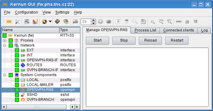
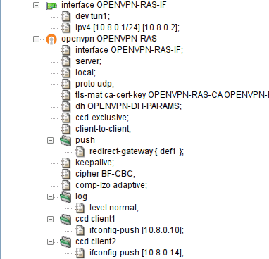
it). An example of GKAT window with OpenVPN-related components is depicted
in Figure 5.87, “OpenVPN components in a GKAT window”. There is an OpenVPN instance
OPENVPN-RAS and its related interface
OPENVPN-RAS-IF, which serves as the Remote Access Server
(RAS). Another OpenVPN instance is OVPN-BRANCH, which
provides a virtual link to branch.
Examples of the OpenVPN configuration described here are available
in the sample configuration file
/usr/local/kernun/conf/samples/cml/openvpn.cml.
Remote Access Server is an OpenVPN server that allows creation of Virtual Private Network between clients outside the company (Road Warriors) and the company server. These clients, if properly configured, can access internal resources (servers) that are not accessible via the external interface, as if the clients were located inside the company. In this chapter we will configure OpenVPN Remote Access Server to create the virtual network using a wizard, which can be started using . Ways of granting road warriors access to the internal resources are outlined in Section 22.3, “Accessing the virtual network”.
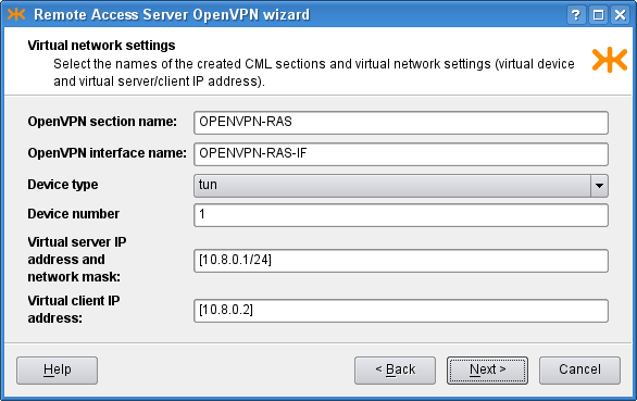
OpenVPN creates a virtual device, and all the VPN communication goes
through this device and is encrypted/decrypted. After choosing the section
names, we need to decide whether to use the tap, or the
tun
interface. TAP works with Ethernet frames and is used to create a
network bridge, while TUN works with IP packets and is used with
routing. We opt for tun and choose an unused device number, 1 in
our case. Then we need to define the virtual network, in which the server
and clients will communicate. We choose [10.8.0.1/24], thus
assigning the server (us) IP address 10.8.0.1. It is very important to
choose a network address that does not collide with any other network, from
which the client would connect. Finally, we specify the virtual IP address
that will be assigned to the other point of the tunnel; we choose
10.8.0.2. The result is shown in Figure 5.88, “RAS: Virtual network settings”.
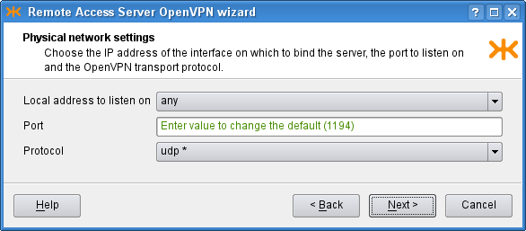
On the second page we choose the IP address to bind the openvpn server
to. We choose the option any, which listens on all the interfaces
in the system. The other option, addr, allows the user to
specify a single address for binding. We leave the port option set to the
default value, 1194. OpenVPN is typically used with the
UDP protocol. The result is shown in
Figure 5.89, “RAS: Physical network settings”.
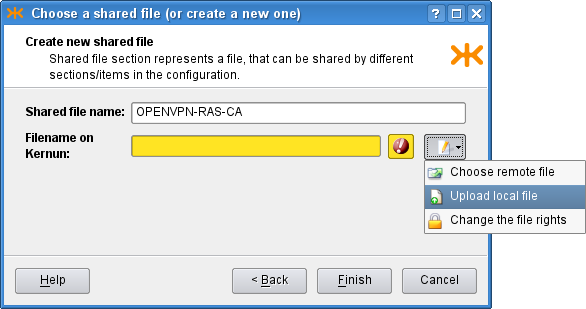
OpenVPN is used to create secure connection, and therefore needs to
authenticate the connected clients. We need to define a certificate of the
used certification authority, a server certificate and a key signed by this
authority. As we have these certificates in separate files in the
PEM format, we check the second radio button
on the third page of the wizard and create new shared files by clicking the
![]() icon and selecting the option. A dialog depicted in Figure 5.90, “Shared file creation dialog” opens.
There we set the
icon and selecting the option. A dialog depicted in Figure 5.90, “Shared file creation dialog” opens.
There we set the shared-file name and upload a local
certificate file to Kernun UTM. We do not have any certificate revocation list
(a list of compromised client certificates) and we leave the
Diffie Hellman parameters unchanged (the parameters are already distributed
with Kernun UTM and this parameter is not a secret). Finally, the third page
should look like Figure 5.91, “RAS: Authentication settings”.

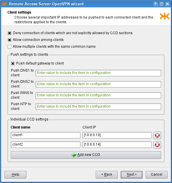
On the Client settings page we can control the interaction between the
clients and the server, and among clients. We allow clients to
connect among each other and we specify that we accept only connections from
clients configured on the clients. In the bottom part of the window, we
configure two clients, client1 and client2,
and set the IP addresses to be pushed to them. If we do not specify the IP
addresses, they will be assigned automatically. On the first page, we chose
the tun interface, which creates a
/30 network for each client. In each of these networks,
the 0. address is the network address, the 3. address is the broadcast
address and the middle two remain for the server and client. Therefore, we need to
choose one of these middle two IP addresses for the clients, for example
[10.8.0.10] and [10.8.0.14]. The tap
interface does not create such networks, so if we chose it, we would be
able to choose the IP addresses freely from the specified [10.8.0.0/24]
network (except the network, broadcast and the server ones). In the middle
part of the page there are several IP addresses that can be pushed to each
connected client; we choose to push only the default gateway. The resulting
page is depicted in Figure 5.92, “RAS: Client settings”.
Finally, on the Miscellaneous page, we can modify the predefined
timeouts, encryption algorithm, compression and log level. In our
example, however, we leave the default values of these parameters and proceed
to the recapitulation, where we can check the selected choices and either finish
the wizard, or return back
to previous pages and modify them. The resulting OpenVPN RAS along with the
OpenVPN Net2Net configuration can be found in the sample file
openvpn.cml in the
/usr/local/kernun/conf/samples/cml directory. The
resulting configuration is shown in Figure 5.93, “RAS OpenVPN wizard: The resulting configuration”
In order to create a configuration for the client to make it able to connect to the created RAS server, it is first necessary to create the client certificate and key with the certification authority that is used for the OpenVPN, and get the certificate of the authority and the two created files to the client computer. Then we create the configuration file of the openvpn program and start the openvpn daemon with this configuration file on the client. An example of the configuration file:
# we are a client
client

# name of the device on the client computer, needs
# to be the same type as on the server (tun/tap)
dev tun1

# communicaton protocol
proto udp

# remote access server hostname (or IP address) and port
remote kernun.kernun.com 1194

# certificate of the Certification Authority (the same
# as on the server
ca /etc/openvpn/keys/ca.crt
# client certificate file and key signed by the CA
cert /etc/openvpn/keys/lj.crt
key /etc/openvpn/keys/lj.key

# additional options
resolv-retry infinite
nobind
comp-lzo adaptive
OpenVPN can be used to create a secure point-to-point connection either
between two Kernun UTM systems, or between a Kernun UTM system and another system. A
virtual point-to-point tunnel interface tun is created in the
system.
This chapter covers the procedure of configuring the point-to-point connection using the Openvpn Network to Network wizard ().
Suppose we want to establish an OpenVPN connection between systems fw and branch. Let us show the configuration for fw; the other side is to be configured complementarily.
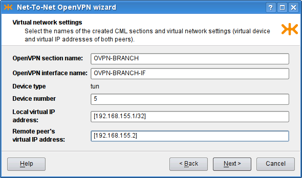
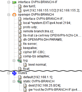
We start with describing the parameters of the virtual network to be
created (see Figure 5.94, “Net-to-Net OpenVPN wizard: Virtual network settings page”). We choose a name for the
openvpn section (OVPN-BRANCH) and for
the respective interface (OVPN-BRANCH-IF),
the ID of the tun interface (5), and the
IP addresses to be assigned to the virtual ends ([192.168.155.1/32] and [192.168.155.2]). Note that the local end is
specified with the /32 mask.
Important
The IP addresses of the virtual endpoints can be chosen almost arbitrarily. However, the address should be chosen so that it does not collide with any of the used/accessible networks.
Important
The TUN interface should be used in the point-to-point mode. In this mode, the mask /32 should be used for the local peer virtual address, which denotes that no subnet should be routed into this interface by default. If a different mask was specified, an implicit route for the given network would be created.
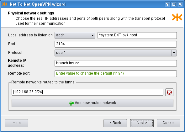
On the following page of the wizard (see Figure 5.95, “Net-To-Net OpenVPN wizard: Physical network settings page”)
we set the physical network parameters: the protocol to be used
(UDP), the local address and port the OpenVPN server would
listen on (the external IP address ^system.EXT.ipv4.host and port
2194). We also set the remote host to be
branch.tns.cz, port
1194. Finally, we add the network [192.168.25.0/24] to be routed through this
tunnel[42].
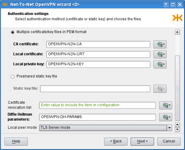
The following page of the wizard (see Figure 5.96, “Net-To-Net OpenVPN wizard: Authentication settings page”) is used to specify authentication options. We can choose between the TLS mode[43] and the Preshared static key file[44]. We have chosen to use the TLS-Server mode and provided the CA certificate, the Local certificate and the Local private key. Finally, on the last page, we can adjust miscellaneous settings; we keep the default values.
The resulting configuration is depicted in Figure 5.97, “Net-To-Net OpenVPN wizard: The resulting configuration”. We have shown the configuration for one of the peers; the complementary configuration should be used on the other.
We have shown how to create virtual connections between peers (1:N in Section 22.1, “Remote Access Server” or 1:1 in Section 22.2, “Network to Network”). If the network traffic is supposed to “go through” the Kernun UTM system, it must be explicitly configured so. There are several ways to achieve this.
One way to set the policy for the network traffic that comes through the virtual network is to provide a proxy for each service that should be accessible from the other side of the virtual network. The proxy would be configured like any other regular proxy.
Another method of interconnecting two (or more) networks is to arrange ip-forwarding among them. See Section 1.4, “Selective Packet Forwarding” for more details.
Logs of the openvpn process are stored in the system log
(/var/log/messages). Logs generated by the Kernun
OpenVPN parent and other auxilliary processes are stored in the Kernun
log (/var/log/kernun-debug).
[42] Given that this is the network that is used in branch.
[43] Either a single PKCS12 or the tuple of PEM files (certification authority's certificate, local peer's certificate and the local peer's private key) should be specified. In this case, one peer must be specified to be the TLS server, and the second to be TLS client.
[44] The same secret key is supposed to be used for both peers. It can be generated from the “Create new shared key” dialog.