To reduce the risk of system failure, Kernun UTM allows to build hot stand-by clusters. As the name suggests, apart from the main Kernun UTM system, there is a copy of it, usually equipped with the same features and configuration, ready to step up and start handling the communication automatically if the main node fails.
Important
When running Kernun in the virtual environment (like VMWare, VirtualBox, Hyper-V etc.), the network adapter to be used for the shared IP address MUST be set the Promiscusous Mode.
VirtualBox: Settings -> Network -> Adapter -> Promiscuous Mode: Allow All
Microsoft Hyper-V: Settings -> Network Adapter -> Advanced Settings -> Enable Spoofing of MAC Addresses
VMWare vSphere: ESXi/ESX Host -> Configuration -> Hardware -> Networking -> Properties -> Edit -> Security tab -> Promiscuous mode -> Accept
Citrix Xen 6.5: no special settings needed
In this chapter, we assign the systems labels “node A” and
“node B”. The system that is currently in charge of traffic control is
called master node within the cluster, while its idle peer is
backup node. Under normal circumstances, node A is master
and node B is backup. Naturally, both nodes must be connected to the same
networks, so we assume that the number of active network interfaces on both
nodes is the same. Figure 5.100, “Simple cluster with two nodes and two networks” illustrates a typical cluster
topology consisting of nodes fw-a and fw-b, securing communication between an
internal network (let us call it INT) and the external
network—Internet (EXT).
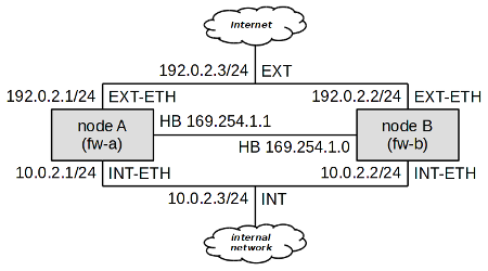
As we can see, at least three IP addresses are needed for each network to build
a two-node cluster; each node must have its own IP address, and a shared cluster IP
address must be present. For example, in the network INT, node A has got IP
address 10.0.2.1, node B
10.0.2.2, and the shared cluster
address is 10.0.2.3. In the
external network, node A has been assigned the address 192.0.2.1, node B 192.0.2.2, and the shared address is
192.0.2.3.
There also needs to be a special “heart-beat” link (simple ethernet
connection between nodes) for cluster nodes to see each other. A dedicated deamon
pikemon listens on this interface on both nodes and informs
each other of their state and priority. In this example node A has address
169.254.1.1 and node B has address
169.254.1.0.
Important
The pikemon daemon determines his peer address
on heart-beat network by performing XOR on the last bit of his own IP address.
If unsure which addresses to choose, use addresses from this sample configuration.
It would be tedious to keep configurations of both cluster members
up-to-date. To simplify cluster administration, Kernun UTM makes it possible to specify
multiple system sections in the same configuration file. Normally,
such a configuration file resides one of the nodes, say node A in our example.
When the configuration is to be applied, we need to recognize which of the systems
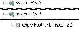
is local and which is remote, and how to reach the remote system. The
apply-host configuration directive serves this purpose. If
not present, the system configuration is applied locally. Otherwise, its parameter
specifies the host name or address and the SSH daemon's port the system
configuration should be applied to. Figure 5.101, “apply-host is used to distinguish
the local system from the remote one” illustrates the use of the apply-host
option.
The existence of two system configurations in the same file would not relieve us of the burden of keeping both system configurations up-to-date. We shall use a section variable (as defined in Section 1, “Configuration Language”) to simplify cluster administration further.
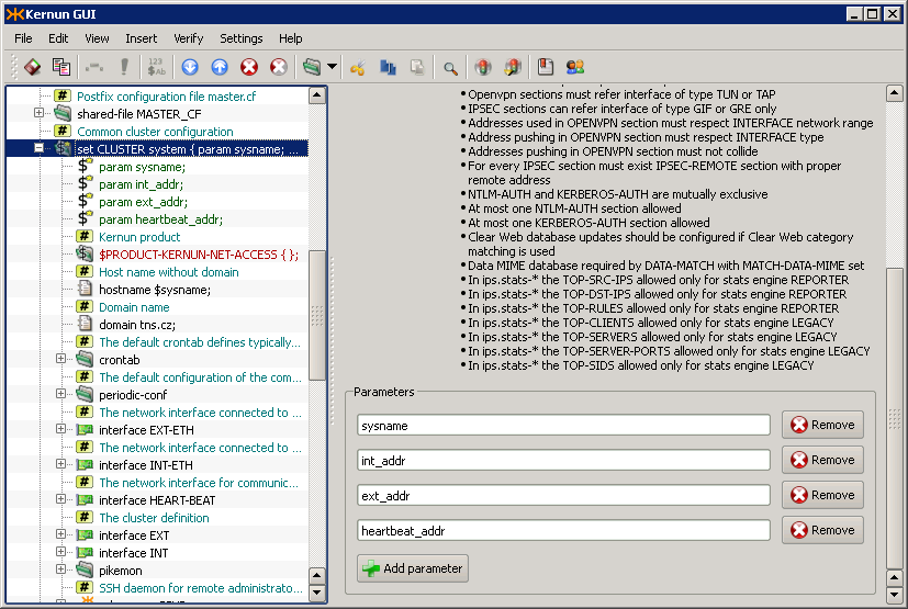
First, let us create a system variable called CLUSTER.
Figure 5.102, “Definition of system variable CLUSTER” shows its definition. Apart from its
name, there are four parameters that distinguish individual nodes of the
cluster:
sysname— The name of the system.int_addr— The internal IP address of the system (not the shared one).ext_addr— The external IP address of the system (not the shared one).heartbeat_addr— The heart-beat IP address of the system.
The system variable CLUSTER includes what both nodes have in common,
which is practically the whole of their configuration. They differ only in
the four parameters described above, and in the way the configuration is applied.
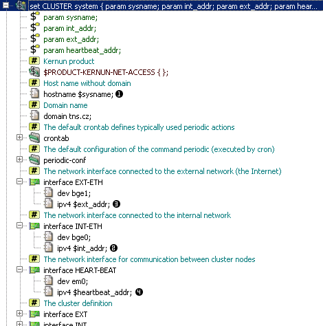
The parameters are used on their appropriate places within the CLUSTER
definition, as shown in Figure 5.103, “Usage of parameters inside CLUSTER definition”. For instance, the
$sysname parameter is used within the hostname
directive to define the system's host name (the row marked
). The real internal address, specified
in parameter 
$int_addr, is used inside the interface
INT-ETH definition (row 
$ext_addr is used to specify
the IP address of interface EXT-ETH (row
) and 
$heartbeat_addr is used
for interface HEART-BEAT (row
).

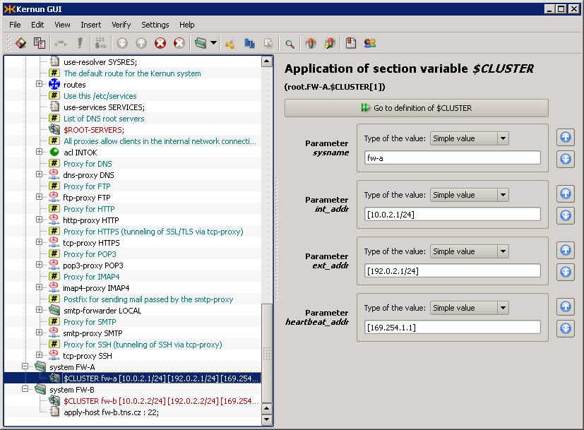
The section variable CLUSTER defined above needs to
be referenced to use its contents to define a real Kernun UTM system. Upon referencing the
variable, its parameter values must be filled in. In our example, we use the
variable CLUSTER twice to define two nodes: system fw-a and
system fw-b, as depicted in Figure 5.104, “Use of variable CLUSTER to define two nodes”.
Cluster functionality, as described above, ensures that if node
A fails, node B takes over automatically, causing minimal communication
blackout (a few seconds at the most). However, if the failure is related only
to one of the network interfaces (i.e. switch port fault, cable or
network interface failure), say on interface EXT of node A,
we would end up with node A still being master for network
INT, but node B being master for network EXT.
This is incorrect, as packets going from internal clients out would go through node
A (master for the internal network), which is not properly connected to the external
network.
To handle such conditions, Kernun UTM makes it possible to tie cluster interfaces together. A self-detector monitors the state of its interfaces by pinging other hosts on all relevant networks. By pinging a remote host, Kernun UTM makes sure that the network interface is working properly, including cabling and switch port.
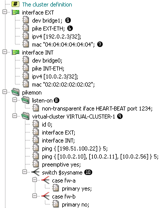
Shared IP addresses (alias “virtual ip addresses” or
“cluster addresses”) are not bound to any physical network interface,
instead they are assigned to a virtual bridge interface
(row 
pike item (row
), binds particular virtual interface to
a physical one. As the virual IP can migrate from one node of cluster to another,
it is necessary for both nodes to advertise same MAC address for this IP,
as defined in 
mac item (row 
Important
For the shared IP address to migrate properly, it is necessary
on some switched to allow one MAC address to be present on multiple switch ports.
On Cisco switches, this requires setting the port-security
option off for those ports.
The pikemon section defines one or more virtual clusters
and a listen socket for it's daemon to listen on (row
). You can choose any free port on the
HEART-BEAT interface.
The virtual-cluster section (row
) defines a logical group of virtual IP
addresses and their properties. In this example we want the EXT and INT interface
to be part of one virtual cluster, so that in case of disruption of communication
of one node with internal network, the node also give up it's master role on
EXT interface. Such disruption is detected by timeout of ping request for defined
group of hosts. When more addresses are defined in one 
ping
item, all of these addresses must fail to respond to ping request for a cluster
node to lower it's priority. In this example, unavailability of
198.51.100.22 will result in a node
loosing master role, on the contrary unavailability of
10.0.2.11 would not, because all of
the 3 hosts in the second ping item must be down.
Tip
When choosing hosts for cluster monitors, take into consideration that the remote host should be always up. The best choice is a router or switch, network servers being the next best option.
Next, we define a switch command (row
) which enables us to use different
configuration for each node (fw-a and fw-b). We set node A (fw-a) to by primary
node of this sample cluster.
In the virual-cluster section, it is possible to influence
another aspect of cluster behavior. Suppose node A had a failure, and node
B has become master. Once node A is recovered, node B could either remain
the master node, or hand the master status back to node A. By default, the former
is true, but we may force the latter by adding the preemptive
directive.
Tip
It is highly recommended to use the preemptive option in
all cluster configurations.
Important
In cluster configuration, both transparent and non-transparent
proxies need to listen on the virtual bridge interface
(INT and EXT interfaces in this sample). The same applies to all packet-filter
rules except for nat-acls which must be set on physical
network interface (INT-ETH or EXT-ETH). It is also suitable for some services
to listen on physical interface addresses. for example SSH daemon should listen
on physical IP address, so it would be possible to connect to both nodes. See
/usr/local/kernun/conf/samples/cml/cluster.cml for more
examples.
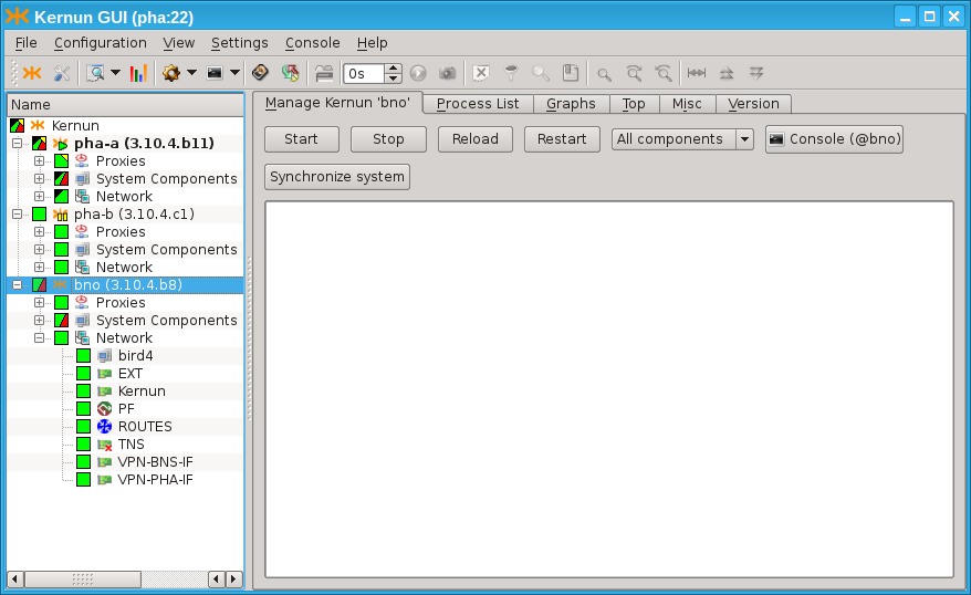
In order to control more systems from a single GUI, set up the following daemons: icamd(8) and icasd(8). The master (icamd) allows the slaves (icasd) to be controlled. The situation is shown in Figure 5.106, “Multiple systems can be controlled using icamd / icasd daemons”: the GUI is connected to the system pha (bold font in the tree view). The systems pha-b and bno can be controlled, because they are connected to the system pha via icamd/icasd.
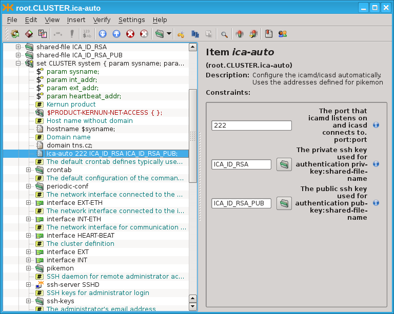
There is a simple way to setup icamd/icasd daemons for the cluster of
two systems. Both daemons are configured by the single item
SYSTEM.ica-auto. See Figure 5.107, “Simplified icamd/icasd configuration using item
ica-auto”. The rsa
key pair is provided for mutual authentication. The communication port
is provided.
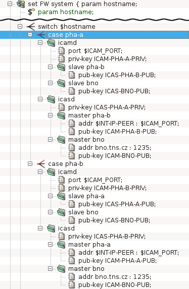
The more complicated topologies are described in the configuration explicitly by the configuration of the icamd/icasd daemons, as shown in Figure 5.108, “Full icamd/icasd configuration”: The configuration for two systems (pha-a and pha-b) is provided. They can control each other. Morover, there is a third system (bno), which is also connected via icamd/icasd (but system bno does not share the configuration with pha-a and pha-b). The configuration is symetric for pha-a and pha-b. Both define the icamd (for being able to control the other systems), and icasd (for being controlled by the other systems). The ssh-key pair is provided for each system's icamd and each system's icasd (6 key pairs in total: 3 key pairs for icamd daemons, 3 key pairs for icasd daemons). The listen port is provided for the icamd daemons. The address and port is provided for each icasd's master section.
Should the configuration be shared among several Kernun systems (for
example in the clusters (Section 24, “High Availability Clusters”) or KBA (Section 25, “Kernun Branch Access”), the SYSTEM.config-sync configuration
item should be used. This item implies that the configuration is
automatically synchronized to the remote system, whe being remotely applied.